Table of Contents
Advertisement
Quick Links
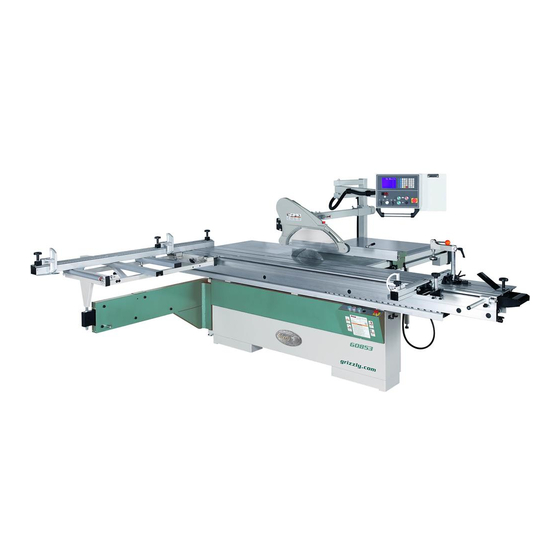
MODEL G0853
14" SLIDING TABLE SAW
w/DRO & CNC RIP FENCE
OWNER'S MANUAL
(For models manufactured since 07/18)
COPYRIGHT © SEPTEMBER, 2021 BY GRIZZLY INDUSTRIAL, INC.
WARNING: NO PORTION OF THIS MANUAL MAY BE REPRODUCED IN ANY SHAPE
OR FORM WITHOUT THE WRITTEN APPROVAL OF GRIZZLY INDUSTRIAL, INC.
#MN21024 PRINTED IN TAIWAN
V1.09.21
Advertisement
Table of Contents

Related Manuals for Grizzly G0853


Summary of Contents for Grizzly G0853
- Page 1 (For models manufactured since 07/18) COPYRIGHT © SEPTEMBER, 2021 BY GRIZZLY INDUSTRIAL, INC. WARNING: NO PORTION OF THIS MANUAL MAY BE REPRODUCED IN ANY SHAPE OR FORM WITHOUT THE WRITTEN APPROVAL OF GRIZZLY INDUSTRIAL, INC. #MN21024 PRINTED IN TAIWAN V1.09.21...
- Page 2 This manual provides critical safety instructions on the proper setup, operation, maintenance, and service of this machine/tool. Save this document, refer to it often, and use it to instruct other operators. Failure to read, understand and follow the instructions in this manual may result in fire or serious personal injury—including amputation, electrocution, or death.
-
Page 3: Table Of Contents
ACCESSORIES ..........78 Assembly ............. 28 Featherboards ..........78 Dust Collection ..........41 Push Sticks ..........81 Power Connection........42 Push Blocks ..........82 Test Run ............43 Recommended Adjustments ......45 SECTION 6: AFTERMARKET ACCESSORIES FROM GRIZZLY ....83... - Page 4 SECTION 7: MAINTENANCE ......85 SECTION 10: PARTS ........108 Schedule ............85 Body ............108 Cleaning & Protecting ........85 Main Tables ..........110 Lubrication ........... 86 Control Panel ..........111 Blade Enclosure ......... 112 SECTION 8: SERVICE ........88 Main Motor ..........
-
Page 5: Introduction
Keep hands out of the line of saw blade. d) Use a push-stick when required. e) Pay particular attention to instructions on reducing risk of kickback. Serial Number f) Do not perform any operation freehand. g) Never reach around or over saw blade. Model G0853 (Mfd. Since 07/18) -
Page 6: Identification
Overhead Control Panel (Upper): Keypad controls for starting/stopping main blade and and DRO for operating motorized rip fence. scoring blade; includes E-stop button. G. Overhead Control Panel (Lower): Controls for adjusting blade height and tilt; includes blade tilt DRO. Model G0853 (Mfd. Since 07/18) -
Page 7: Controls & Components
B. Main Blade OFF Button. Turns both motors OFF. C. Scoring Blade ON Button. Starts scoring blade. D. Emergency Stop Button. Turns both motors OFF and disables control panel. Twist clock- wise until it pops out to reset. Model G0853 (Mfd. Since 07/18) - Page 8 Figure 4. Miter fence controls. Flip Stop. Used for quick, precise measure- ments for repeatable cuts when using miter fence. M. Miter Fence Scale. Helps measure length of cut during miter operations. Model G0853 (Mfd. Since 07/18)
- Page 9 0.01" (0.1mm). performing non-through cuts. AB. M+ Key. Increases distance between blade AJ. mm/inch Selection Key. Press once to and rip fence in increments of 0.01" (0.1mm). toggle between inch and metric units. Model G0853 (Mfd. Since 07/18)
- Page 10 0.1°. AO. Emergency Stop Button. Stops both motors AS. Blade Tilt Switch. Increases or decreases and disables control panel. To reset, twist angle of saw blades anywhere between clockwise until button pops out. 0°–45°. Model G0853 (Mfd. Since 07/18)
-
Page 11: Glossary Of Terms
The following is a list of common definitions, terms and phrases used throughout this manual as they relate to this sliding table saw and woodworking in general. Become familiar with these terms for assembling, adjusting or operating this machine. Your safety is VERY important to us at Grizzly! Arbor: Metal shaft extending from the drive Non-Through Cut: A sawing operation in which mechanism, to which saw blade is mounted. -
Page 12: Sliding Table Saw Capacities
SLIDING TABLE SAW CAPACITIES Customer Service #: (570) 546-9663 • To Order Call: (800) 523-4777 • Fax #: (800) 438-5901 MODEL G0853 14" SLIDING TABLE SAW 134" 126" Ripping Width 51" Crosscut 134" 45" 62" 134" Miter Cut 90º Miter Cut 45º... -
Page 13: Machine Data Sheet
MACHINE DATA SHEET Customer Service #: (570) 546-9663 · To Order Call: (800) 523-4777 · Fax #: (800) 438-5901 MODEL G0853 14" 10 HP 3‐PHASE SLIDING TABLE SAW WITH DRO AND CNC FENCE Product Dimensions: Weight................................1890 lbs. Width (side-to-side) x Depth (front-to-back) x Height............... 133 x 147 x 66 in. - Page 14 The information contained herein is deemed accurate as of 11/8/2021 and represents our most recent product specifications. Model G0853 PAGE 2 OF 3 Due to our ongoing improvement efforts, this information may not accurately describe items previously purchased. -12- Model G0853 (Mfd. Since 07/18)
- Page 15 The information contained herein is deemed accurate as of 11/8/2021 and represents our most recent product specifications. Model G0853 PAGE 3 OF 3 Due to our ongoing improvement efforts, this information may not accurately describe items previously purchased. -13- Model G0853 (Mfd. Since 07/18)
-
Page 16: Section 1: Safety
Never operate under the influence of drugs or injury or blindness from flying particles. Everyday alcohol, when tired, or when distracted. eyeglasses are NOT approved safety glasses. -14- Model G0853 (Mfd. Since 07/18) - Page 17 Make sure they are properly installed, you experience difficulties performing the intend- undamaged, and working correctly BEFORE ed operation, stop using the machine! Contact our operating machine. Technical Support at (570) 546-9663. -15- Model G0853 (Mfd. Since 07/18)
-
Page 18: Additional Safety For Sliding Table Saws
Cutting operation “freehand”. Turn OFF saw and wait metal, glass, stone, tile, etc. increases risk of until blade is completely stopped before removing operator injury due to kickback or flying particles. workpiece. -16- Model G0853 (Mfd. Since 07/18) -
Page 19: Preventing Kickback
Ensure rip fence is adjusted parallel with the blade; otherwise, the chances of kickback are • Use featherboards or anti-kickback devices extreme. Take the time to check and adjust to prevent or slow down kickback. the rip fence before cutting. -17- Model G0853 (Mfd. Since 07/18) -
Page 20: Section 2: Power Supply
Nominal Voltage ......440V, 480V sure it is connected to a power supply circuit that Cycle ............60 Hz meets the specified circuit requirements. Phase ............ 3-Phase Power Supply Circuit ......20 Amps -18- Model G0853 (Mfd. Since 07/18) -
Page 21: 440V Conversion
Conduit Conduit Ground Ground Figure 8. Typical setup of a permanently The Model G0853 can be converted for 440V connected machine. operation. This conversion consists of: 1) Disconnecting the saw from power, 2) moving the Grounding Instructions transformer T1 wire from the 220V to 440V termi-... - Page 22 To convert G0853 for 440V operation: Remove scoring motor overload relay (see Figure 11), and replace with Shihlin TH-12S DISCONNECT MACHINE FROM POWER! overload relay. Set amperage dial to 1.6A. Remove electrical panel cover (see Figure 9). Electrical Panel Cover...
-
Page 23: Section 3: Setup
IMPORTANT: Save all packaging materials until you are completely satisfied with the machine and have resolved any issues between Grizzly or the shipping agent. You MUST have the original pack- aging to file a freight claim. It is also extremely helpful if you need to return your machine later. -
Page 24: Hardware Recognition Chart
Hardware Recognition Chart -22- Model G0853 (Mfd. Since 07/18) -
Page 25: Inventory
Rip Fence ........... 1 G. Cabinet Door ..........1 H. Sliding Table ..........1 Miter Fence ..........1 Extension Table Leg w/Foot ...... 1 Figure 14. G0853 Inventory 2. Figure 13. G0853 Inventory 1. -23- Model G0853 (Mfd. Since 07/18) - Page 26 If you cannot find an item on this list, care- fully check around/inside the machine and packaging materials. Often, these items get lost in packaging materials while unpack- ing or they are pre-installed at the factory. Figure 15. G0853 Inventory 3. -24- Model G0853 (Mfd. Since 07/18)
-
Page 27: Cleanup
Figure 16. T23692 Orange Power Degreaser. Repeat Steps 2–3 as necessary until clean, then coat all unpainted surfaces with a quality metal protectant to prevent rust. -25- Model G0853 (Mfd. Since 07/18) -
Page 28: Site Considerations
Only install in an Shadows, glare, or strobe effects that may distract access restricted location. or impede the operator must be eliminated. 133" 205" 147" 271" Figure 17. Minimum working clearances. -26- Model G0853 (Mfd. Since 07/18) -
Page 29: Lifting & Placing Saw
Remove top of crate. Position forklift forks as wide as they can be while still fitting under center opening (see Figure 18). Figure 18. Example of how to insert forks for lifting table saw off pallet. -27- Model G0853 (Mfd. Since 07/18) -
Page 30: Assembly
Figure 19. Location of mounting plates for Adjustment Bolt Sliding Table securing sliding table to machine frame. (1 of 2) Figure 21. Sliding table parallelism adjustment bolt (1 of 2). -28- Model G0853 (Mfd. Since 07/18) - Page 31 Hinge Sleeves & Pins Figure 26. Cabinet door attached to hinges. Figure 23. Mounting hole access on rear side at back of saw. Figure 24. Middle mounting hole access through cabinet access hole. -29- Model G0853 (Mfd. Since 07/18)
- Page 32 11. Fully tighten cap screws from Step 9. Hex Nut Set Screw Figure 29. Location of fasteners used to install and level small extension table. -30- Model G0853 (Mfd. Since 07/18)
- Page 33 Rip Fence Leadscrew Housing Figure 30. Location of mounting fasteners on back of rip fence leadscrew housing. Extension L-Bracket Table Figure 32. L-bracket on rip fence attached to large extension table. -31- Model G0853 (Mfd. Since 07/18)
- Page 34 Figure 34. Rip fence base mounted on bracket. Figure 36. Rip fence sensor housing attached to rip fence base. 23. Install (1) 16mm plastic cap in center pin hole and (2) 22mm plastic caps over cap screw holes. -32- Model G0853 (Mfd. Since 07/18)
- Page 35 30. Secure support bar by threading (1) M8-1.25 x 50 knob bolt and 8mm fender washer into T-nut (see Figure 40). Crosscut Table Support Bar Figure 40. Attaching support bar to crosscut table. -33- Model G0853 (Mfd. Since 07/18)
- Page 36 (see Figure 42). b. Align T-slot bolt with slot in pre-installed angle scale bar (see Figure 42). Note: Angle scale lock knob, T-slot plate, and 8mm fender washer will help secure crosscut fence in later step. -34- Model G0853 (Mfd. Since 07/18)
- Page 37 Figure 46. Pivot Lock Knob Thumb Knob Fence T-bolt Extension Angle Scale Lock Knob Crosscut Figure 44. Crosscut fence secured to table. Fence Figure 46. Installing clamp assembly on crosscut fence extension. -35- Model G0853 (Mfd. Since 07/18)
- Page 38 (see Figure 50). Studs Lower Guard Arm Figure 48. Lower guard arm installed on studs. Middle Guard Arm Post Figure 50. Middle guard arm post attached to lower guard arm. -36- Model G0853 (Mfd. Since 07/18)
- Page 39 (see Figure 54). middle guard arm (see Figure 52). 3" Dust Port 4" Dust Port Figure 54. Installing 3" dust port on middle Figure 52. Installing 4" dust port in middle guard guard arm. arm. -37- Model G0853 (Mfd. Since 07/18)
- Page 40 (see Figure 56). Upper Control Panel Guard Arm Figure 58. Control panel attached to upper guard arm. Figure 56. Upper guard arm installed on middle guard arm post. -38- Model G0853 (Mfd. Since 07/18)
- Page 41 Note: There should be no strain on cord as it enters control panel. The Model G0853 does not ship with a main blade. Refer to Blade Requirements and Blade Selection beginning on Page 50 when purchasing the main blade.
- Page 42 66. Close blade cover. Center sliding table and Figure 63. Main blade arbor parts and tools for lock in place. changing blade. Before proceeding with the next steps, wear gloves to protect your hands when handling and installing the blade. -40- Model G0853 (Mfd. Since 07/18)
-
Page 43: Dust Collection
To connect dust collection hoses: Fit 5" dust hose over dust port on rear side of cabinet, as shown in Figure 66, and secure with hose clamp. Figure 66. 5" dust hose attached to dust port. -41- Model G0853 (Mfd. Since 07/18) -
Page 44: Power Connection
Strain Relief restrict others from starting the machine. Figure 70. Location of power supply junction box. Insert incoming power wires through strain relief at bottom of junction box. Figure 69. Disconnecting power from machine. -42- Model G0853 (Mfd. Since 07/18) -
Page 45: Test Run
BEFORE operating the machine again. The Troubleshooting table in the SERVICE section of this manual can help. Figure 72. Resetting Emergency Stop button. -43- Model G0853 (Mfd. Since 07/18) - Page 46 (refer to Figure 7 on Page 8) on over- Power Supply head control panel. Junction Box 13. Press Emergency Stop buttons. R and T Ground Connections Figure 73. Up-close view of power supply terminal inside junction box. -44- Model G0853 (Mfd. Since 07/18)
-
Page 47: Recommended Adjustments
Aligning Scoring Blade ....Page 58 • Blade Tilt Calibration ...... Page 92 • Sliding Table Parallel Adjustment ... Page 94 • Squaring Crosscut Fence to Blade ..Page 95 • Calibrating Rip Fence ..... Page 96 • -45- Model G0853 (Mfd. Since 07/18) -
Page 48: Section 4: Operations
11. Turns machine OFF immediately after cut is complete and waits for blades to completely stop before removing workpieces. The Model G0853 does not ship with a main If you are not experienced with this type blade. Refer to Blade Requirements and... -
Page 49: Workpiece Inspection
Minor Warping: Slightly cupped workpieces can be safely supported with cupped side facing the table or fence; however, work- pieces supported on the bowed side will rock during the cut, which could cause kickback. -47- Model G0853 (Mfd. Since 07/18) -
Page 50: Blade Guard
To ensure that the guard does its job effectively, it MUST be centered over blade and properly adjusted so it moves up and down to accommo- date workpieces and maintain coverage over the blade after the workpiece exits. -48- Model G0853 (Mfd. Since 07/18) -
Page 51: Riving Knife
Guard Covers Riving Knife Installation & Removal Tools Needed The G0853 features two dust hood assemblies Straightedge ............1 for either straight cuts or angled cuts. Use the flat blade cover when performing straight (90°) Wrench 19mm ........... 1 cuts or the wide (bubble) cover for angled cuts. -
Page 52: Blade Requirements
The thickness of the blade body and teeth can be measured with calipers or any precision measur- ing device. Blade Size Requirements: • Body Thickness: 0.108" • Kerf (Tooth) Thickness: 0.118" -50- Model G0853 (Mfd. Since 07/18) -
Page 53: Blade Selection
Thin Kerf Blade: A blade with thinner kerf than a standard blade. Since the spreader/riving knife included with this table saw is sized for standard Figure 88. Crosscutting blade. blades, thin kerf blades cannot be used on this saw. -51- Model G0853 (Mfd. Since 07/18) -
Page 54: Adding/Deleting Blade Dimensions
Use F2 and F3 keys to scroll through list, and PROG. stop on line to be deleted. START STOP Press and hold F5 key for three seconds to delete line. Figure 92. Tool-Box blade dimension screen. Press F1 to return to main screen. -52- Model G0853 (Mfd. Since 07/18) -
Page 55: Changing Main Blade Height
0.1°. Tip: Press and hold button down for continu- ous movement. Monitor changes to blade angle in blade tilt readout (see Figure 95), and release button when desired angle is reached. -53- Model G0853 (Mfd. Since 07/18) -
Page 56: Changing Blade Speed
Inspect the belt. If there is any evidence of damage or excessive wear, replace it (refer to Belt Service on Page 90). The Model G0853 has three main blade speeds—3000, 4000, and 5000 RPM. These Position belt on correct arbor and motor pul-... -
Page 57: Changing Main Blade
Insert arbor locking pin into table hole shown with a new blade. in Figure 99. Arbor The Model G0853 does not ship with a main Locking Pin blade. Refer to Blade Requirements and Blade Selection beginning on Page 50 when purchasing the main blade. -
Page 58: Replacing & Aligning Scoring Blade
Facing Right the workpiece surface. This prevents workpiece tearout. Flange The scoring blade included with the Model G0853 Arbor has wedge-shaped teeth that narrow at the top, Arbor as shown in Figure 102. With this style of scoring blade, the kerf thickness is adjusted by changing the height of the scoring blade. - Page 59 10. Align scoring blade to main blade, as instruct- Figure 104). ed in the next subsection. Arbor Scoring Blade Wrench Bolt 19mm Wrench Flange Figure 104. Scoring blade, flange, arbor hex bolt, 19mm wrench, and arbor wrench. -57- Model G0853 (Mfd. Since 07/18)
- Page 60 Perform a test cut and check for chip-out. — If there is chip-out, repeat this procedure until corrected. Figure 107. Example of straightedge placed flat against main and scoring blades. -58- Model G0853 (Mfd. Since 07/18)
-
Page 61: Setting Up Crosscut Fence
0° stop bolts securing crosscut fence to table. are properly adjusted before using the fence. Refer to Squaring Crosscut Fence to Blade on Page 95 for further details. -59- Model G0853 (Mfd. Since 07/18) - Page 62 Rotate fence so 0° stop block is up against stop bolt (see Figure 113), then rotate latch into catch and secure by tightening knurled thumb knob. Figure 115. Crosscut table positions along sliding table. -60- Model G0853 (Mfd. Since 07/18)
- Page 63 3" mark on fence scale is exactly 3" from desired position, then retighten lock lever to blade tooth. secure table. Tighten pivot knob, Repeat measurement in Step 5. — If measurement is not exactly 3", repeat Steps 2–7 until it is. -61- Model G0853 (Mfd. Since 07/18)
-
Page 64: Using Cnc Rip Fence
Take all safety precautions, turn blades ON, the cut. and make the cut. Turn motors OFF, allow blades to come to a complete stop, and remove workpiece from table. -62- Model G0853 (Mfd. Since 07/18) - Page 65 CAL. left-hand corner of screen. PROG. Press START key. Rip fence will move to starting position. START STOP 10. Load workpiece onto table. Figure 121. Location of Grooving/Concealed Cuts key. -63- Model G0853 (Mfd. Since 07/18)
- Page 66 11. Repeat Steps 7–10 until operation is com- inch plete. F1 key may be pressed at any time to end operation and return to main screen. CAL. PROG. START STOP Figure 123. Location of Incremental Dimension key. -64- Model G0853 (Mfd. Since 07/18)
- Page 67 Press START key to move rip fence to new position. Repeat Steps 1–2, but enter second desired width of cut. Fence Release Button Figure 126. Location of rip fence release button. -65- Model G0853 (Mfd. Since 07/18)
-
Page 68: Saving Rip Fence Positions
– CAL. PROG. START STOP Figure 128. Example of Run Programs screen selected using F2 and F3 keys. Note: The other icons shown on this screen are not functional on the Model G0853. -66- Model G0853 (Mfd. Since 07/18) -
Page 69: Rip Cutting
Sliding Table. • To use the machine as a traditional table The Model G0853 has the capability of rip cutting saw, refer to Rip Cutting with Rip Fence on large panels (see Figure 130). The sliding table Page 68. - Page 70 Figure 134. Location of crosscut table lock lever. Lock sliding table in place with table lock lever (see Figure 135). Horizontal Figure 137. Rip fence positions. Sliding Table Lock Lever Figure 135. Location of sliding table lock lever. -68- Model G0853 (Mfd. Since 07/18)
-
Page 71: Crosscutting
Figure 138, then retighten lock lever. The Model G0853 can crosscut full-size pan- els with the fence in the front or rear position, although it is easier to load full-size panels with... - Page 72 To understand how to move the crosscut table, Page 69. refer to Positioning Crosscut Table Along Sliding Table on Page 60. Take all necessary safety precautions, con- nect saw to power, then perform cutting operation. -70- Model G0853 (Mfd. Since 07/18)
- Page 73 Take all necessary safety precautions, con- Page 70, and secure in place. nect saw to power, then perform cutting operation. Perform Steps 3–4 in Crosscutting Full- Size Panels. Set rip fence to desired width of cut. -71- Model G0853 (Mfd. Since 07/18)
-
Page 74: Miter Cutting
Miter Cutting Position fence for desired angle of cut (see Figures 145–146). The G0853 can perform miter cuts using either the crosscut fence or the miter fence. The cross- cut fence can be positioned for miter cuts from 0° to 45°, and the angle scale on the crosscut table is Workpiece graduated in 1°... - Page 75 Load workpiece onto crosscut table. The setup should look similar to Figures 145–146 on Page 72. 10. Take all necessary safety precautions, con- nect saw to power, then perform cutting operation. -73- Model G0853 (Mfd. Since 07/18)
-
Page 76: Dado Cutting
Typically, dadoes can be cut using either a Fence dedicated dado blade or a standard saw blade. Workpiece However, since the Model G0853 cannot accept dado blades, a standard blade must be used. See Making Grooves/Concealed Cuts on Page Figure 150. Second cut for a single-blade dado. -
Page 77: Rabbet Cutting
However, because the Model G0853 cannot accept dado blades, rab- bets must be cut with a standard saw blade only. Raise blade to desired depth of rabbet chan- nel desired. -
Page 78: Resawing
IMPORTANT: This table saw can only resaw ⁄ " Wood Screw wood that is less than 8" tall, and the rip fence must be used (rather than the sliding table). ⁄ " Assembled Resaw Barrier Figure 154. Resaw barrier. -76- Model G0853 (Mfd. Since 07/18) - Page 79 (see 12. When finished resawing, remove resaw bar- Figure 155). rier and reposition blade guard over blade. Workpiece Fence Resaw Barrier " Connection Figure 155. Ideal completed resaw cut. -77- Model G0853 (Mfd. Since 07/18)
-
Page 80: Section 5: Shop Made Safety Accessories
Step 3 will bend without breaking. cuts are too far apart). Cut a 30º angle at one end of board. NOTICE Only Steps 1–3 are required to make a clamp-mounted featherboard. Refer to Page 80 for instructions on clamping. -78- Model G0853 (Mfd. Since 07/18) - Page 81 Figure 158. Miter bar pattern. Now, proceed to Mounting Featherboard in Miter Slot on Page 80. Drill ⁄ " hole in center of bar, then countersink bottom to fit ⁄ "-20 flat head screw. -79- Model G0853 (Mfd. Since 07/18)
- Page 82 Note: The featherboard should be placed firmly enough against the workpiece to keep it against the fence but not so tight that it is difficult to feed the workpiece. -80- Model G0853 (Mfd. Since 07/18)
-
Page 83: Push Sticks
⁄ " Grid increase comfort. from the blade! Figure 164. Template for a basic shop-made push stick (not shown at actual size). -81- Model G0853 (Mfd. Since 07/18) -
Page 84: Push Blocks
Lip for pushing workpiece ⁄ " Grid 9"−10" Minimum Length Figure 167. Template for a shop-made push block (shown at 50% of full size). -82- Model G0853 (Mfd. Since 07/18) -
Page 85: Section 6: Aftermarket Accessories From Grizzly
This blade also features laser To reduce this risk, only install accessories cut anti-vibration slots, practically eliminating the recommended for this machine by Grizzly. vibration that resonates in standard blades. NOTICE Refer to our website or latest catalog for additional recommended accessories. - Page 86 W1008—Plastic Blast Gate 5" T20502—Face Shield Crown Protector 7" We've hand picked a selection of commonly used T20503—Face Shield Window dust collection components for the Model G0853. T20451—“Kirova” Clear Safety Glasses T20452—“Kirova” Anti-Reflective S. Glasses W1008 T20456—DAKURA Safety Glasses, Black/Clear...
-
Page 87: Section 7: Maintenance
Lubricate slide shafts (Page 86). • • Lubricate blade tilt gear (Page 86). Figure 175. Recommended products for protect- • Lubricate trunnions (Page 87). • Lubricate rip fence leadscrew (Page 87). ing unpainted cast iron/steel part on machinery. -85- Model G0853 (Mfd. Since 07/18) -
Page 88: Lubrication
Lube Blade Tilt Gear Tilt Gear Figure 177. Tilt gear. -86- Model G0853 (Mfd. Since 07/18) - Page 89 Tilt the blade through its full range of movement to spread the grease. Grease Fitting Trunnions Leadscrew Figure 179. Grease fitting for rip fence leadscrew. Figure 178. Trunnion lubrication locations (table removed for clarity). -87- Model G0853 (Mfd. Since 07/18)
-
Page 90: Section 8: Service
11. Contactor not energized/at fault. 11. Test all legs for power; repair/replace if at fault. 12. Motor or motor bearings at fault. 12. Replace motor. 13. Start delay module at fault. 13. Adjust to correct delay; replace module. -88- Model G0853 (Mfd. Since 07/18) - Page 91 1. Press M+ button on control panel to move rip fence control panel back within travel limits; or press release button on flashing/ side of rip fence base, manually push fence back unresponsive. within travel limits, and calibrate rip fence (Page 96). -89- Model G0853 (Mfd. Since 07/18)
-
Page 92: Belt Service
(see Figure 182). Scoring Motor Flat Belt Cam Lock Main Motor Belt Figure 180. Location of scoring motor flat belt. Figure 182. Location of main motor belt and cam lock (table removed for clarity). -90- Model G0853 (Mfd. Since 07/18) - Page 93 Lever Note: The cam lock will automatically posi- tion motor for correct belt tension. Figure 183. Main motor belt tension controls (table removed for clarity). Close cabinet door before reconnecting machine to power. -91- Model G0853 (Mfd. Since 07/18)
-
Page 94: Calibrating Blade Tilt
Use machinist's square to check if main blade is square to table (see Figure 185). Blade Tilt Switch Micro-Adjust Button Figure 186. Controls for calibrating blade tilt. Blade 90° Square Table Figure 185. Machinist's square against blade and table. -92- Model G0853 (Mfd. Since 07/18) -
Page 95: Riving Knife Mounting Block
Properly re-install riving knife as described on Page 49, close blade cover, properly reposi- tion blade guard, and move sliding table back to center position. -93- Model G0853 (Mfd. Since 07/18) -
Page 96: Sliding Table Parallel Adjustment
Once sliding table parallelism is within 0.004" from one end to the other, retighten hex bolts Miter Slot and re-install access panels. Marked Tooth Figure 188. Measuring distance between miter slot and blade at each end of sliding table. -94- Model G0853 (Mfd. Since 07/18) -
Page 97: Squaring Crosscut Fence To Blade
Lock Knob & Block Use crosscut fence to cut ⁄ " off of each side Figure 190. Stop block against 0° stop bolt. of test piece, then cut side 1 again (make five cuts total). -95- Model G0853 (Mfd. Since 07/18) -
Page 98: Calibrating Rip Fence
Move crosscut fence stop block against 0° stop bolt, then retighten pivot lock knob to secure fence in place. 10. Repeat Steps 5–6 until both measurements are with ⁄ ". -96- Model G0853 (Mfd. Since 07/18) - Page 99 Raise main blade all the way up and tilt to 0°. Raise leadscrew housing until fence base Move rip fence as close as possible to main gap is even, then retighten hex nuts and blade. cap screw. -97- Model G0853 (Mfd. Since 07/18)
- Page 100 — If test piece does not measure 10" wide, then rip fence needs to be calibrated. Proceed to Step 5. Mounting Bracket Figure 197. Location of rip fence components used to adjust parallelism. -98- Model G0853 (Mfd. Since 07/18)
- Page 101 Rip fence is now properly calibrated to blade. inch CAL. .150 inch PROG. START STOP Figure 198. Location of CAL key. Figure 199. Actual measurement of test piece entered in CAL screen. Press F1 to return to main screen. -99- Model G0853 (Mfd. Since 07/18)
-
Page 102: Section 9: Wiring
Technical Support at (570) 546-9663. The photos and diagrams included in this section are best viewed in color. You can view these pages in color at www.grizzly.com. -100- Model G0853 (Mfd. Since 07/18) -
Page 103: Scoring Motor Wiring
Motor Wiring Scoring Motor Wiring 220V 440V Ground Ground (Rewired for 440V operation) Main Motor Wiring 220V 440V (Rewired for 440V operation) READ ELECTRICAL SAFETY -101- Model G0853 (Mfd. Since 07/18) ON PAGE 100! -
Page 104: Motor Wiring Diagram
Motor Wiring Diagram Scoring Saw Motor READ ELECTRICAL SAFETY -102- Model G0853 (Mfd. Since 07/18) ON PAGE 100! -
Page 105: System Wiring Diagram
System Wiring Diagram Electrical Panel Circuit Board Wiring Diagram Pin 11 Pin 7 Pin 12 Pin 8 READ ELECTRICAL SAFETY -103- Model G0853 (Mfd. Since 07/18) ON PAGE 100! -
Page 106: Electrical Components
Figure 200. Electrical box wiring and components. Figure 201. 220V power supply wiring. Figure 203. Transformer wiring. Figure 202. Contactor and OL relay wiring. Figure 204. Timer and relay wiring. READ ELECTRICAL SAFETY -104- Model G0853 (Mfd. Since 07/18) ON PAGE 100! - Page 107 Figure 208. Scoring motor wiring. Figure 206. Cabinet door limit switch wiring. Figure 209. Fuse wiring. Left Right Figure 210. Master power switch wiring. Figure 207. Blade guard limit switch wiring. READ ELECTRICAL SAFETY -105- Model G0853 (Mfd. Since 07/18) ON PAGE 100!
- Page 108 Figure 211. Emergency stop button wiring. Figure 213. Power connection box wiring. Figure 214. Rip fence motor wiring. Figure 212. Circuit board wiring. Figure 215. Front control panel wiring. READ ELECTRICAL SAFETY -106- Model G0853 (Mfd. Since 07/18) ON PAGE 100!
- Page 109 Electrical Components (Cont.) Figure 216. Overhead control panel wiring. READ ELECTRICAL SAFETY -107- Model G0853 (Mfd. Since 07/18) ON PAGE 100!
-
Page 110: Section 10: Parts
SECTION 10: PARTS We do our best to stock replacement parts when possible, but we cannot guarantee that all parts shown are available for purchase. Call (800) 523-4777 or visit www.grizzly.com/parts to check for availability. Body 16-1 BUY PARTS ONLINE AT GRIZZLY.COM! -108- Model G0853 (Mfd. - Page 111 PHLP HD SCR M6-1 X 10 P08530098 LOCK WASHER 12MM P08530045 JUNCTION BOX P08530099 FLAT WASHER 12MM P08530046 TERMINAL BAR 4P PB2504 100 P08530100 PLATE BUY PARTS ONLINE AT GRIZZLY.COM! -109- Model G0853 (Mfd. Since 07/18) Scan QR code to visit our Parts Store.
-
Page 112: Main Tables
MAIN TABLE P08530112 LOCK NUT M16-2 P08530106 EXTENSION TABLE (LARGE) P08530113 FLAT WASHER 16MM P08530107 FLAT WASHER 10MM P08530114 HEX NUT M16-2 BUY PARTS ONLINE AT GRIZZLY.COM! -110- Model G0853 (Mfd. Since 07/18) Scan QR code to visit our Parts Store. -
Page 113: Control Panel
205 P08530205 CONTROL PANEL LABEL 211 P08530211 PANEL PLUG 18MM 206 P08530206 CONTROL PANEL PLATE 212 P08530212 SCORING BLADE ON BUTTON RENY R9C10VN BUY PARTS ONLINE AT GRIZZLY.COM! -111- Model G0853 (Mfd. Since 07/18) Scan QR code to visit our Parts Store. -
Page 114: Blade Enclosure
HEX NUT M8-1.25 P08530319 CAP SCREW M12-1.75 X 45 P08530345 SET SCREW M8-1.25 X 55 P08530320 SLIDE SHAFT P08530346 HEX NUT M8-1.25 BUY PARTS ONLINE AT GRIZZLY.COM! -112- Model G0853 (Mfd. Since 07/18) Scan QR code to visit our Parts Store. -
Page 115: Main Motor
428 P08530428 BALL JOINT ROD END M10-1.5 X 60 P08530411 GAS SPRING 25KG, 60L 429 P08530429 SHAFT P08530412 HEX NUT M6-1 BUY PARTS ONLINE AT GRIZZLY.COM! -113- Model G0853 (Mfd. Since 07/18) Scan QR code to visit our Parts Store. -
Page 116: Main Blade Arbor
GAS SPRING 25KG, 60L P08530531 BALL BEARING LM30UU P08530563 LOCK WASHER 10MM P08530532 LEVER SHAFT M8-1.25 X 15, 12 X 166 P08530564 RIVING KNIFE BUY PARTS ONLINE AT GRIZZLY.COM! -114- Model G0853 (Mfd. Since 07/18) Scan QR code to visit our Parts Store. -
Page 117: Scoring Blade Arbor
SCORING BLADE ARBOR HOUSING P08530622 INT RETAINING RING 15MM P08530610 PHLP HD SCR M6-1 X 10 P08530623 FLAT WASHER 6MM P08530611 BALL BEARING 6202LLB BUY PARTS ONLINE AT GRIZZLY.COM! -115- Model G0853 (Mfd. Since 07/18) Scan QR code to visit our Parts Store. -
Page 118: Scoring Blade Adjustment
HEX NUT M16-2 P08530873 CAP SCREW M8-1.25 X 12 P08530829 CAP SCREW M8-1.25 X 35 P08530874 FLAT WASHER 8MM P08530830 LOCK WASHER 8MM BUY PARTS ONLINE AT GRIZZLY.COM! -116- Model G0853 (Mfd. Since 07/18) Scan QR code to visit our Parts Store. -
Page 119: Scoring Blade Motor
909-1 P08530909-1 MOTOR FAN COVER P08530917 HEX BOLT M6-1 X 16 909-2 P08530909-2 MOTOR FAN P08530918 LOCK WASHER 14MM 909-3 P08530909-3 MOTOR JUNCTION BOX BUY PARTS ONLINE AT GRIZZLY.COM! -117- Model G0853 (Mfd. Since 07/18) Scan QR code to visit our Parts Store. -
Page 120: Crosscut Swing-Arm
1020 P08531020 FLAT WASHER 8MM 1042 P08531042 SCREW CAP 1021 P08531021 SET SCREW M8-1.25 X 30 1043 P08531043 ROLLER BEARING 30202 BUY PARTS ONLINE AT GRIZZLY.COM! -118- Model G0853 (Mfd. Since 07/18) Scan QR code to visit our Parts Store. -
Page 121: Crosscut Table
1127 1117 1131 1124 1120 1133 1119 1134 1123 1129 1132 1121 1150 1122 1115-1 1130 1115-2 1128 1121 1115 1115-3 BUY PARTS ONLINE AT GRIZZLY.COM! -119- Model G0853 (Mfd. Since 07/18) Scan QR code to visit our Parts Store. - Page 122 BRACE T-SLOT LOCK CLAMP 1162 P08531162 CAP SCREW M8-1.25 X 20 1130 P08531130 FIXED HANDLE 47 X 140, M8-1.25 1163 P08531163 FLAT WASHER 8MM BUY PARTS ONLINE AT GRIZZLY.COM! -120- Model G0853 (Mfd. Since 07/18) Scan QR code to visit our Parts Store.
-
Page 123: Crosscut Fence
1273 1272 1272 1271 1271 1287 1287 1286 1285 1286 1285 1284 1284 1279 1279 1283 1283 1282 1282 1281 1281 BUY PARTS ONLINE AT GRIZZLY.COM! -121- Model G0853 (Mfd. Since 07/18) Scan QR code to visit our Parts Store. - Page 124 1236 P08531236 THUMB NUT M8-1.25 KD 1286 P08531286 SET SCREW M8-1.25 X 8 1237 P08531237 ACORN NUT M8-1.25 1287 P08531287 SET SCREW M5-.8 X 8 BUY PARTS ONLINE AT GRIZZLY.COM! -122- Model G0853 (Mfd. Since 07/18) Scan QR code to visit our Parts Store.
-
Page 125: Rip Fence & Electrical Box
1496 1477 1457 1495 1482 1494 1483V2 1492 1493 1485 1491 1484 1480 1497 1490 1406 1405 1404 1490-1 1490-2 1490-3 BUY PARTS ONLINE AT GRIZZLY.COM! -123- Model G0853 (Mfd. Since 07/18) Scan QR code to visit our Parts Store. - Page 126 1355 P08531355 HEX NUT M20-2.5 THIN 1412 P08531412 STRAIN RELIEF TYPE-3 1/4 1356 P08531356 CAP SCREW M6-1 X 45 1413 P08531413 L-BRACKET BUY PARTS ONLINE AT GRIZZLY.COM! -124- Model G0853 (Mfd. Since 07/18) Scan QR code to visit our Parts Store.
- Page 127 1456 P08531456 PHLP HD SCR M3-.5 X 8 1497 P08531497 TERMINAL 54P 1457 P08531457 BUTTON HD CAP SCR M5-.8 X 10 BUY PARTS ONLINE AT GRIZZLY.COM! -125- Model G0853 (Mfd. Since 07/18) Scan QR code to visit our Parts Store.
-
Page 128: Sliding Table
1563 1565 1548 1566 1549 1562 1564 1568 1569 1550 1571 1580 1575 1578 1572 1574 1576 1579 1570 1577 1573 BUY PARTS ONLINE AT GRIZZLY.COM! -126- Model G0853 (Mfd. Since 07/18) Scan QR code to visit our Parts Store. - Page 129 EXT RETAINING RING 12MM 1535 P08531535 BUTTON HD CAP SCR M6-1 X 16 1599 P08531599 PLASTIC GUIDE WHEEL 1536 P08531536 HEX NUT M6-1 BUY PARTS ONLINE AT GRIZZLY.COM! -127- Model G0853 (Mfd. Since 07/18) Scan QR code to visit our Parts Store.
-
Page 130: Overhead Control Panel
1680 1665 1613 1666 1667 1626 1624 1623 1622 1668 1670 1622 1683 1623 1669 1624 1625 1607 1608 1609 1610 BUY PARTS ONLINE AT GRIZZLY.COM! -128- Model G0853 (Mfd. Since 07/18) Scan QR code to visit our Parts Store. - Page 131 1645 P08531645 OFF BUTTON RENY R9C01VN 1687 P08531687 MAIN BLADE ELEVATION RENY R9C20VN 1646 P08531646 HOLE PLUG 22MM 1688 P08531688 SCORING BLADE ON RENY R9C10VN BUY PARTS ONLINE AT GRIZZLY.COM! -129- Model G0853 (Mfd. Since 07/18) Scan QR code to visit our Parts Store.
-
Page 132: Blade Guard
1719-7 1719-6 1719-5 1717-1 1717-2 1719-4 1717-3 1718-2 1718-1 1718-3 1717-4 1717-5 1718-8 1717-6 1718 1717-7 1717 1718-7 1718-6 1718-5 1718-4 BUY PARTS ONLINE AT GRIZZLY.COM! -130- Model G0853 (Mfd. Since 07/18) Scan QR code to visit our Parts Store. - Page 133 TAP SCREW M4 X 10 1720-15 P08531720-15 PIVOT SHAFT 1717-5 P08531717-5 KNOB BOLT M8-1.25 X 40, 16-LOBE, D26 1720-16 P08531720-16 LOCKING HANDLE BUY PARTS ONLINE AT GRIZZLY.COM! -131- Model G0853 (Mfd. Since 07/18) Scan QR code to visit our Parts Store.
-
Page 134: Accessories
1812-7 1812-9 1851 1812-8 1854 1812-10 1853 1852 1855 1841-5 1851-4 1841-4 1851-3 1841-3 1851-2 1841-2 1841 1841-1 1851-1 1851-5 1841-6 BUY PARTS ONLINE AT GRIZZLY.COM! -132- Model G0853 (Mfd. Since 07/18) Scan QR code to visit our Parts Store. - Page 135 WRENCH 30MM COMBO 1816-2 P08531816-2 ADJ HANDLE M10-1.5 X 20, 66L 1855 P08531855 WRENCH 19/24MM OPEN-ENDS 1816-3 P08531816-3 KNOB M8-1.25, D40, BALL BUY PARTS ONLINE AT GRIZZLY.COM! -133- Model G0853 (Mfd. Since 07/18) Scan QR code to visit our Parts Store.
-
Page 136: Labels & Cosmetics (Front)
P08531908 GRIZZLY.COM LABEL 1904 P08531904 GLASSES/RESPIRATOR LABEL 1909 P08531909 MACHINE ID LABEL 1905 P08531905 READ MANUAL LABEL 1910 P08531910 GRIZZLY NAMEPLATE–LARGE BUY PARTS ONLINE AT GRIZZLY.COM! -134- Model G0853 (Mfd. Since 07/18) Scan QR code to visit our Parts Store. -
Page 137: Labels & Cosmetics (Back)
PART # DESCRIPTION 1911 P08531911 ELECTRICITY LABEL 1913 P08531913 DISCONNECT POWER LABEL 1912 P08531912 CRUSH HAZARD LABEL 1914 P08531914 AMPUTATION HAZARD LABEL BUY PARTS ONLINE AT GRIZZLY.COM! -135- Model G0853 (Mfd. Since 07/18) Scan QR code to visit our Parts Store. -
Page 138: Labels & Cosmetics (Side)
Safety labels help reduce the risk of serious injury caused by machine hazards. If any label comes off or becomes unreadable, the owner of this machine MUST replace it in the original location before resuming operations. For replacements, contact (800) 523-4777 or www.grizzly.com. BUY PARTS ONLINE AT GRIZZLY.COM! -136- Model G0853 (Mfd. -
Page 139: Warranty & Returns
WARRANTY & RETURNS Grizzly Industrial, Inc. warrants every product it sells for a period of 1 year to the original purchaser from the date of purchase. This warranty does not apply to defects due directly or indirectly to misuse, abuse, negligence, accidents, repairs or alterations or lack of maintenance.
Need help?
Do you have a question about the G0853 and is the answer not in the manual?
Questions and answers