Table of Contents
Advertisement
Quick Links
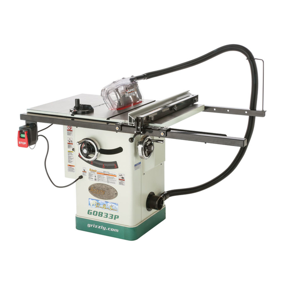
MODEL G0833P
POLAR BEAR SERIES
®
10" HYBRID TABLE SAW
w/RIVING KNIFE
OWNER'S MANUAL
(For models manufactured since 06/17)
COPYRIGHT © JUNE, 2017 BY GRIZZLY INDUSTRIAL, INC.
WARNING: NO PORTION OF THIS MANUAL MAY BE REPRODUCED IN ANY SHAPE
OR FORM WITHOUT THE WRITTEN APPROVAL OF GRIZZLY INDUSTRIAL, INC.
#19042BLJHMN PRINTED IN CHINA
V1.06.17
Advertisement
Table of Contents

Related Manuals for Grizzly Polar Bear G0833P


Summary of Contents for Grizzly Polar Bear G0833P
- Page 1 (For models manufactured since 06/17) COPYRIGHT © JUNE, 2017 BY GRIZZLY INDUSTRIAL, INC. WARNING: NO PORTION OF THIS MANUAL MAY BE REPRODUCED IN ANY SHAPE OR FORM WITHOUT THE WRITTEN APPROVAL OF GRIZZLY INDUSTRIAL, INC. #19042BLJHMN PRINTED IN CHINA V1.06.17...
- Page 2 This manual provides critical safety instructions on the proper setup, operation, maintenance, and service of this machine/tool. Save this document, refer to it often, and use it to instruct other operators. Failure to read, understand and follow the instructions in this manual may result in fire or serious personal injury—including amputation, electrocution, or death.
-
Page 3: Table Of Contents
SECTION 1: SAFETY ........9 Safety Instructions for Machinery ....9 SECTION 6: AFTERMARKET ACCESSORIES Additional Safety for Table Saws ....11 FROM GRIZZLY ..........57 Preventing Kickback ........12 SECTION 7: MAINTENANCE ......59 Protecting Yourself From Kickback....12 Schedule ............ -
Page 4: Introduction
ID label. This will help us help you faster. tions, specifications, drawings, and photographs in this manual. Sometimes we make mistakes, but Grizzly Technical Support our policy of continuous improvement also means 1815 W. Battlefield that sometimes the machine you receive is slightly different than shown in the manual. -
Page 5: Identification
Identification Become familiar with the names and locations of the controls and features shown below to better understand the instructions in this manual. Dust Collection Miter Left Blade ⁄ " Dust Hose Extension Gauge Port Guard Wing Right Extension Fence START/ Wing STOP... -
Page 6: Controls & Components
Controls & B. Handwheel Locks: Lock blade height and angle when tightened (one on each Components handwheel). C. Blade Tilt Handwheel: Adjusts angle of blade tilt from 90°–45°. D. Blade Height Handwheel: Adjusts blade To reduce your risk of height from 0"–3 ⁄... -
Page 7: Glossary Of Terms
The following is a list of common definitions, terms and phrases used throughout this manual as they relate to this table saw and woodworking in general. Become familiar with these terms for assembling, adjusting or operating this machine. Your safety is VERY important to us at Grizzly! Arbor: A metal shaft extending from the drive... -
Page 8: G0833P Machine Data Sheet
MACHINE DATA SHEET Customer Service #: (570) 546-9663 · To Order Call: (800) 523-4777 · Fax #: (800) 438-5901 MODEL G0833P 10" HYBRID TABLE SAW WITH RIVING KNIFE, POLAR BEAR SERIES Product Dimensions: Weight................................396 lbs. Width (side-to-side) x Depth (front-to-back) x Height..............62 x 39 x 47-3/4 in. Footprint (Length x Width)....................... - Page 9 Motors: Main Horsepower..............................2 HP Phase............................Single-Phase Amps............................... 16A/8A Speed..............................3450 RPM Type......................... TEFC Capacitor-Start Induction Power Transfer ........................Poly-V Belt Drive Bearings..................... Shielded & Permanently Lubricated Main Specifications: Main Information Table Saw Type............................Hybrid Maximum Blade Diameter......................... 10 in. Arbor Size..............................
- Page 10 Construction Table........................Precision-Ground Cast Iron Wings........................Precision-Ground Cast Iron Cabinet........................... Pre-Formed Steel Trunnions............................. Cast Iron Fence Assembly......................Steel w/Aluminum Fence Rails................................Steel Miter Guage Construction........................Cast Iron Guard............................. Clear Plastic Body/Cabinet Paint Type/Finish....................Powder Coated Arbor Bearings....................Sealed & Permanently Lubricated Other Related Information Number of Dust Ports............................
-
Page 11: Section 1: Safety
SECTION 1: SAFETY For Your Own Safety, Read Instruction Manual Before Operating This Machine The purpose of safety symbols is to attract your attention to possible hazardous conditions. This manual uses a series of symbols and signal words intended to convey the level of impor- tance of the safety messages. - Page 12 WEARING PROPER APPAREL. Do not wear FORCING MACHINERY. Do not force machine. clothing, apparel or jewelry that can become It will do the job safer and better at the rate for entangled in moving parts. Always tie back or which it was designed. cover long hair.
-
Page 13: Additional Safety For Table Saws
Additional Safety for Table Saws Serious cuts, amputation, or death can occur from contact with rotating saw blade during operation. Workpieces, broken blades, or flying particles thrown by blade can blind or strike operators or bystanders with deadly force. To reduce the risk of these hazards, operator and bystanders MUST completely heed the hazards and warnings below. -
Page 14: Preventing Kickback
Preventing Kickback • Never move the workpiece backwards or try to back it out of a cut while the blade is mov- ing. If you cannot complete a cut for some reason, stop the saw motor and allow the Below are ways to avoid the most common blade to completely stop before backing the causes of kickback: workpiece out. -
Page 15: Section 2: Power Supply
SECTION 2: POWER SUPPLY Availability Circuit Information Before installing the machine, consider the avail- A power supply circuit includes all electrical ability and proximity of the required power supply equipment between the breaker box or fuse panel circuit. If an existing circuit does not meet the in the building and the machine. -
Page 16: Grounding Requirements
Grounding Requirements This machine MUST be grounded. In the event of certain malfunctions or breakdowns, grounding Serious injury could occur if you connect reduces the risk of electric shock by providing a machine to power before completing setup path of least resistance for electric current. process. -
Page 17: Converting Voltage To 115V
Converting Voltage Use wire nuts to connect wires as indicated in Figure 7. Twist wire nuts onto their respec- to 115V tive wires and wrap them with electrical tape so they will not come loose. The voltage conversion MUST be performed by Connect an electrician or qualified service personnel. -
Page 18: Section 3: Setup
IMPORTANT: Save all packaging materials until you are completely satisfied with the machine and have resolved any issues between Grizzly or the shipping agent. You MUST have the original pack- aging to file a freight claim. It is also extremely helpful if you need to return your machine later. -
Page 19: Inventory
Inventory The following is a list of items shipped with your machine. Before beginning setup, lay these items out and inventory them. If any non-proprietary parts are missing (e.g. a nut or a washer), we will gladly replace them; or for the sake of expediency, replacements can be obtained at your local hardware store. - Page 20 Box Contents Cont'd (Figure 12) Front Rail Tube 62" ........1 U. Front Rail Tape Scale ......... 1 Rear Rail 55" ..........1 W. Front Rail 57" ..........1 X. Fence Assembly ......... 1 Fasteners (Figure 13) Cap Screws M10-1.5 x 25 (Wing/Table) ..........
-
Page 21: Hardware Recognition Chart
Hardware Recognition Chart USE THIS CHART TO MATCH UP HARDWARE DURING THE INVENTORY AND ASSEMBLY PROCESS. Flat Head Screw -19- Model G0833P (Mfd. Since 06/17) -
Page 22: Cleanup
Cleanup Gasoline and petroleum products have low flash The unpainted surfaces of your machine are points and can explode coated with a heavy-duty rust preventative that or cause fire if used to prevents corrosion during shipment and storage. clean machinery. Avo i d This rust preventative works extremely well, but it u sing t h e s e p r o du c t s will take a little time to clean. -
Page 23: Site Considerations
Site Considerations Weight Load Physical Environment Refer to the Machine Data Sheet for the weight The physical environment where the machine is of your machine. Make sure that the surface upon operated is important for safe operation and lon- which the machine is placed will bear the weight gevity of machine components. -
Page 24: Assembly
Assembly Slide groove on back of each handwheel over handwheel shaft pin, as shown in Figure 18. The machine must be fully assembled before it can be operated. Before beginning the assembly process, refer to Needed for Setup and gather all listed items. - Page 25 While a helper holds wings in place, attach — If outside end of extension wing tilts up, each extension wing to main table with (3) place strip of masking tape along top edge M10-1.5 x 25 cap screws, 10mm lock wash- of main table to shim end of extension wing down (see Figure 22).
- Page 26 10. Install front rail tube onto front rail with (5) 14. Install saw blade as outlined in Blade Installation on Page 33. M6-1 x 16 cap screws, 6mm flat wash- ers, and 6mm lock washers, as shown in Figure 24. Finger-tighten fasteners. 15.
- Page 27 17. Slide fence up against right hand edge of 18. Carefully slide fence so it barely touches saw miter slot, and lock it in place. Examine how blade and lock it in place. fence lines up with miter slot. 19. Lightly mark "0" location on fence tube (under Note: It is permissible for back of fence to indicator line on pointer window) with a pen- pivot outward not more than...
- Page 28 23. Attach switch to bottom left-hand side of front 24. Attach dust hose support to rear rail with (1) rail using (2) M5-.8 x 14 cap screws, 5mm M6-1 hex nut, 6mm flat washer, and M6-1 lock washers, and 5mm flat washers, as wing nut, as shown in Figure 30, so open shown in Figure 29.
-
Page 29: Dust Collection
Dust Collection Slide one adapter onto 1 ⁄ " dust port (see Figure 32), until it fits snugly. Attach dust hose to dust hose support, then insert dust port into rear of blade guard assembly (see Figure 32). This machine creates a lot of wood chips/ dust during operation. -
Page 30: Test Run
Test Run Insert switch disabling pin through green ON/ START button, as shown in Figure 34. Once assembly is complete, test run the machine to ensure it is properly connected to power and safety components are functioning correctly. If you find an unusual problem during the test run, ON / START immediately stop the machine, disconnect it from Button... -
Page 31: Section 4: Operations
Read books/magazines or get formal training before beginning any proj- ects. Regardless of the content in this sec- tion, Grizzly Industrial will not be held liable for accidents caused by lack of training. -29- Model G0833P (Mfd. Since 06/17) -
Page 32: Workpiece Inspection
Workpiece Non-Through & Inspection Through Cuts Non-Through Cuts Some workpieces are not safe to cut on this machine or may need to be modified before they A non-through cut is a sawing operation where can be safely cut. Before cutting, inspect all the blade does not protrude above the top face of workpieces for the following: the wood stock, as shown in the Figure below. -
Page 33: Blade Requirements
Blade Selection Through Cuts A through cut is a sawing operation in which the workpiece is completely sawn through, as shown in the Figure below. Examples of through cuts are This section on blade selection is by no means rip cuts, cross cuts, miter cuts, and beveled cuts. comprehensive. - Page 34 Combination blade features: Thin Kerf Blade: A blade with thinner kerf than • Designed to cut both with and across grain a standard blade. Since the spreader/riving knife • 40-50 teeth included with this table saw is sized for standard •...
-
Page 35: Blade Installation
Blade Installation While pressing arbor lock, use included arbor wrench to loosen and remove arbor nut, flange, and blade (see Figure 43). Arbor nut has right-hand threads; rotate counterclock- Review this section, even if your saw blade came wise to loosen. pre-installed. -
Page 36: Blade Guard Assembly
Blade Guard Assembly In order to work properly, the spreader cannot be bent or misaligned with the blade. If the spreader gets accidentally bent, take The term "blade guard" refers to the assembly the time to straighten it or just replace it. that consists of the clear polycarbonate shield Using a bent or misaligned spreader will and dust enclosure, the spreader, and the anti-... - Page 37 The blade guard, when properly installed, Install blade guard dust port and dust collec- should be set up similarly to Figure 47. It tion hose, as shown in Figure 49, and attach should pivot freely up and down and return to hose to dust collection port on table saw body (refer to Page 27).
- Page 38 Disabling Pawls Enabling Pawls You might disable the pawls if you are concerned To enable the pawls, lift up on each pawl and about them scratching a delicate workpiece, or move them outward and down until they both touch the table surface, as shown in Figure 50 if you believe that they will obstruct a narrow workpiece and cause feeding difficulty or loss of on Page 35.
-
Page 39: Riving Knife
Riving Knife To ensure that riving knife works safely, it MUST be aligned with and correctly adjust- The riving knife works in the same manner as ed to blade. Refer to Page 67 to check or the spreader on the blade guard assembly. It is a adjust riving knife alignment. -
Page 40: Ripping
Ripping Set fence to desired width of cut on scale. Adjust blade height so highest saw tooth pro- trudes no more than ⁄ " above workpiece. "Ripping" means cutting with the grain of a natural wood workpiece. In man-made materials such as Set up safety devices such as featherboards MDF or plywood, ripping means cutting length- or other anti-kickback devices, making sure... -
Page 41: Crosscutting
Crosscutting Miter Cuts "Crosscutting" means cutting across the grain of A miter is an angled crosscut. Miters are usually a natural wood workpiece, usually with a miter cut in the same manner as crosscuts, using the saw. In other man-made materials, such as MDF miter gauge and a predetermined mark on the or plywood, crosscutting means cutting across the workpiece. -
Page 42: Blade Tilt/Bevel Cuts
Blade Tilt/Bevel Cuts The Model G0833P can accommodate dado blades up to 10" in diameter. However, you MUST install the included riving knife while using a 10" diameter dado blade, as it provides a barrier When the blade tilt collar bolts are properly adjust- behind the blade and reduces the risk of hands ed (as described starting on Page 63), the blade being pulled into the blade if kickback occurs. - Page 43 Cutting Dadoes with a Dado Blade To cut a dado with a dado blade: Because dado blades are much wider than stan- DISCONNECT MACHINE FROM POWER! dard blades, they place a greater amount of force against the workpiece when cutting. This addition- Adjust dado blade to desired depth of cut.
-
Page 44: Rabbet Cutting
Rabbet Cutting Align blade to cut one side of dado, as shown in Figure 61. Commonly used in furniture joinery, a rabbet is an L-shaped groove cut in the edge of the workpiece. Rabbets can be cut with either a dado blade or a Blade Cut 1 standard saw blade. - Page 45 Cutting Rabbets with a Standard Blade Always use push sticks, featherboards, A ripping blade is typically the best blade to use push paddles and other safety accessories for cutting rabbets when using a standard blade whenever possible to increase safety and because it removes sawdust very efficiently.
-
Page 46: Resawing
Resawing Resawing operations require proper pro- cedures to avoid serious injury. Extra care must be taken to prevent kickback when resawing. Any tilting or movement of the workpiece away from the fence will cause kickback. Be certain that stock is flat and straight. - Page 47 Making Resaw Barrier Making Auxiliary Fence When resawing, the resaw barrier acts in tandem An auxiliary fence is necessary if you are resawing with the rip fence to provide tall support for the a workpiece that is taller than it is wide. The fence workpiece.
- Page 48 Components Needed: Place auxiliary fence board against fence Flat Head Cap Screws M6-1 x (Auxiliary Fence tube. Place a thin metal shim (such as a Width + Fence Tube Width) ......3 ruler) between table and bottom of auxiliary Wood* ⁄ "...
- Page 49 Resawing Operations Place workpiece against auxiliary fence and slide resaw barrier against workpiece, as The table saw motor is pushed to its limits when shown in Figure 72. Now clamp resaw bar- resawing. If the motor starts to bog down, slow rier to top of table saw at both ends.
- Page 50 Plug in table saw, turn it ON, and use a push stick or push block to feed workpiece through blade, using a slow and steady feed rate. The danger of kickback increases relative to the depth of a cut. Reduce the risk of kick- Note: We recommend making a series of back by making multiple passes to achieve light cuts that get progressively deeper, to...
-
Page 51: Section 5: Shop Made Safety Accessories
SECTION 5: SHOP MADE SAFETY ACCESSORIES Featherboards We recommend using a bandsaw for mak- ing fingers in the next step because it tends Easily made from scrap stock, featherboards to be safer. A table saw can be used, but it provide an added degree of protection against will over-cut the underside of the ends, pro- kickback, especially when used together with... - Page 52 Rout a ⁄ "– ⁄ " wide slot 4"–5" long in Mark a 4" line through center of countersunk workpiece and 1"–2" from short end of feath- hole in center, then use a jig saw with a nar- erboard (see Figure 75). row blade to cut it out.
- Page 53 Mounting Featherboards w/Clamps Mounting Featherboard in Miter Slot Lower saw blade, then adjust fence to desired Lower saw blade, then adjust fence to desired width and secure it. width and secure it. Place workpiece against fence, making sure Place workpiece evenly against fence, mak- it is 1"...
-
Page 54: Push Sticks
Push Sticks Supporting: A second push stick can be used to keep the workpiece firmly against the fence while cutting. When using a push stick in this manner, only apply pressure before the blade; otherwise, When used correctly, push sticks reduce the risk pushing the workpiece against or behind the of injury by keeping hands away from the blade blade will increase the risk of kickback (see "Push... -
Page 55: Push Blocks
Push Blocks The notched end of the push block is then used to push the workpiece the rest of the way through the cut, keeping the operator's hands at a safe distance from the blade. A push stick is often When used correctly, a push block reduces the used at the same time in the other hand to sup- risk of injury by keeping hands away from the... -
Page 56: Narrow-Rip Auxiliary Fence & Push Block
Narrow-Rip Auxiliary Note: We recommend cutting hardwood board oversize, then jointing and planing it Fence & Push Block to correct size to make sure board is square and flat. Only use furniture-grade plywood or kiln-dried hardwood to prevent warping. There are designs for hundreds of specialty jigs Pre-drill and countersink eight pilot holes ⁄... - Page 57 Using Auxiliary Fence & Push Block Place auxiliary fence on table and clamp Auxilliary Fence it to fence at both ends, then adjust dis- tance between auxiliary fence and blade— Blade this determines how wide workpiece will be Workpiece ripped (see Figure 89). Push Stick for Side Push...
-
Page 58: Outfeed & Support Tables
Outfeed & Support Crosscut Sled Tables A crosscut sled (see Figure 93) is a fantastic way to improve the safety and accuracy of cross- One of the best accessories for improving the cutting on the table saw. Most expert table saw safety and ease of using a table saw is simply plac- operators use a crosscut sled when they have ing a large table (outfeed table) behind the saw to... -
Page 59: Section 6: Aftermarket Accessories From Grizzly
Specifications: 450 CFM, 7.2" To reduce this risk, only install accessories static pressure, 2 cubic foot bag, and 30 micron recommended for this machine by Grizzly. filter. Motor is 1HP, 110V/220V, 14A/7A. NOTICE Model G0710 Refer to our website or latest catalog for additional recommended accessories. - Page 60 Figure 100. D3096 Featherboard. one blade instead of 3 (24T rip, 50T combination and 80T crosscut). ⁄ " arbor, ⁄ " kerf. Figure 98. Forrest Woodworker II Saw Blade. www.grizzly.com 1-800-523-4777 order online at or call -58- Model G0833P (Mfd. Since 06/17)
-
Page 61: Section 7: Maintenance
SECTION 7: MAINTENANCE Cleaning & Protecting To prevent serious per- sonal injury from shock or accidental startup, always disconnect power Cleaning the Model G0833P is relatively easy. from machine before Vacuum excess wood chips and sawdust, and doing any maintenance. wipe off the remaining dust with a dry cloth. -
Page 62: Lubrication
Lubrication Worm Gear, Bull Gear & Leadscrew Lubrication Type ... T26419 or NLGI#2 Equivalent Amount ............Dab Lubrication Frequency .....6–12 Months It is essential to clean components before lubri- cating them because dust and chips build up on Clean away any built up grime and debris from the lubricated components and make them hard to worm gear, bull gear, and leadscrew (see Figures move. -
Page 63: Section 8: Service
SECTION 8: SERVICE Review the troubleshooting and procedures in this section if a problem develops with your machine. If you need replacement parts or additional help with a procedure, call our Technical Support. Note: Please gather the serial number and manufacture date of your machine before calling. Troubleshooting Symptom Possible Cause... - Page 64 Symptom Possible Cause Possible Solution 1. Remount rip fence. Adjust fence (Page 71) to ensure Rip fence does not 1. Rip fence mounted/adjusted incorrectly. move smoothly. adjustment screws are not too tight. 2. Rails dirty or sticky. 2. Clean and wax rails. Material moves 1.
-
Page 65: Blade Tilt Stops
Blade Tilt Stops The table saw features stop collars that stop the blade exactly at 45° and 90° when tilting it with the handwheel. The stops have been set at the factory and should require no adjustments, unless you notice that your cuts are not accurate. Note: The tilt scale reads "0"... - Page 66 Repeat Steps 2–3 to verify that collar adjust- Open right access cover, loosen set screws on 45° stop collar (see Figure 109), then turn ment you made was correct. When adjust- ment is satisfactory, close motor door. collar one turn away from trunnion bracket. This will allow you to adjust blade to exactly Setting 45°...
-
Page 67: Miter Slot To Blade Parallelism
Miter Slot to Blade With end of adjustable square just touching tip, lock square in place. Now, mark car- Parallelism bide tip with a marker where you made this measurement. Your table saw will give the best results if the miter slot and the rip fence are adjusted paral- The saw blade is sharp. - Page 68 10. Refer to Figures 113–114 for shim place- Loosen (4) table mounting bolts securing table top to base (see Figure 112), and lightly ment. If distance A is shorter than B, shim(s) tap table in direction needed to square table will need to be placed under corners #1 and to blade.
-
Page 69: Spreader Or Riving Knife Alignment
Spreader or Riving 11. Tighten one table mounting bolt a small amount and then repeat with the others, Knife Alignment tightening each down the same amount. Continue this process with all the bolts, tight- ening them a little each time until they are all secure. - Page 70 Loosen (2) cap screws on mounting block, then adjust either top or bottom control set screws Alignment or side control set screws (see Figure 117) to Zone move it the needed direction. Spreader or Riving Knife Blade Set Screw Figure 116. Spreader/riving knife alignment (1 of 4) zone.
-
Page 71: Fence Adjustments
Fence Adjustments Re-install table insert. Follow Checking Alignment, Steps 1–3. There are four main adjustments for the fence: — If spreader/riving knife is in alignment height off the table, squareness, parallelism with zone, no additional steps are necessary. the miter slot, and clamping pressure. These adjustments are interconnected and some repeti- —If spreader/riving knife is still not in align- tion may be needed when adjusting. - Page 72 Parallelism & Clamping Pressure Install fence onto table, then loosen fence knobs (see Figure 119), pull fence up from Set screws on the rear side of the fence flange center, and tighten each knob. position the fence parallel to the blade and adjust the clamping pressure to hold fence securely.
- Page 73 Optional Offset Fence Adjustment Examine how fence lines up with miter slot along its length. Some woodworkers prefer to offset the rear of " from the blade, as shown in Figure the fence —If fence and miter slot are flush from front 122, to help prevent the workpiece from binding to rear, as shown in Figure 121A, proceed and burning.
-
Page 74: Fence Scale Calibration
Fence Scale Table/Dado Insert Calibration Adjustment The fence scale indicator window, shown in The table/dado insert must sit perfectly flush with Figure 123, can be calibrated with the fence the table to provide a smooth, continuous surface scale if you notice that your cuts do not accurately for the workpiece to slide over. -
Page 75: Miter Gauge Adjustments
Miter Gauge Place square evenly against face of miter gauge and blade, as shown in Figure 126. Adjustments Blade Square The miter gauge can be adjusted so it is perpen- dicular to the blade and snug in the T-slot. Tools Needed 90°... -
Page 76: Belt Tension & Replacement
Belt Tension & Pulley Replacement The drive belt stretches slightly as the saw is used. Most of the belt stretching will happen dur- ⁄ " ing the first 16 hours of use, but it may continue through continued use. If you notice that the belt is slipping, it will need to be tensioned. -
Page 77: Section 9: Wiring
Technical Support at (570) 546-9663. The photos and diagrams included in this section are best viewed in color. You can view these pages in color at www.grizzly.com. -75- Model G0833P (Mfd. Since 06/17) -
Page 78: Wiring Diagram
Wiring Diagram SWITCH BOX ON/OFF SWITCH 115 VAC 5-20 Plug 230 VAC (As Recommended) 6-20 PLUG Neutral Load Line Rewired for 115V KEDU HY56 20A 230V 35A 120V Ground Ground Rewired for 115V Start Capacitor Capacitor 200–240MFD 40MFD 250VAC 450VAC 115V/230V MOTOR Motor Rewired... -
Page 79: Electrical Components
Electrical Components Capacitors Circuit Breaker ON/OFF Switch Figure 130. Motor capacitors. Figure 132. Switch box components. Motor Junction Figure 131. Motor junction box. READ ELECTRICAL SAFETY -77- Model G0833P (Mfd. Since 06/17) ON PAGE 75! -
Page 80: Section 10: Parts
SECTION 10: PARTS We do our best to stock replacement parts when possible, but we cannot guarantee that all parts shown are available for purchase. Call (800) 523-4777 or visit www.grizzly.com/parts to check for availability. Body 2 3 4 21 20... -
Page 81: Trunnion
Trunnion 106-1 106-7 106-5 106-3 106-2 106-4 106-6 106-8 106-9 106-10 106-11 105 106 127 128 101 102 122 123 108 109 119 120 136 137 138 182 181 183 172 120 -79- Model G0833P (Mfd. Since 06/17) - Page 82 Trunnion Parts List PART # DESCRIPTION REF PART # DESCRIPTION P0833P101 LOCK NUT M16-2 P0833P148 SPRING BRACKET P0833P102 FLAT WASHER 16MM P0833P149 FLANGE RING P0833P103 CAP SCREW M8-1.25 X 20 P0833P150 FLAT HD CAP SCR M5-.8 X 50 P0833P104 LOCK WASHER 8MM P0833P151 SAW BLADE 10"...
-
Page 83: Power Switch
Power Switch 224X (for 115V conversion) 222-1 REF PART # DESCRIPTION REF PART # DESCRIPTION P0833P221 TAP SCREW M3.5 X 19 227 P0833P227 LOCK WASHER 5MM P0833P222 S/S SWITCH W/STOP PADDLE KEDU HY56 228 P0833P228 FLAT WASHER 5MM 222-1 P0833P222-1 PADDLE SWITCH LOCKOUT PIN 229 P0833P229 CLAMP-ON TERMINAL RING P0833P223 SWITCH BOX... -
Page 84: Blade Guard
Blade Guard 301 302 303 304 REF PART # DESCRIPTION REF PART # DESCRIPTION P0833P301 FLAT HD CAP SCR M4-.7 X 10 P0833P319 ANTI-KICKBACK PAWL P0833P302 GUARD SUPPORT (FRONT) P0833P320 SPACER P0833P303 GUARD SUPPORT (REAR) P0833P321 BUTTON HD CAP SCR M4-.7 X 6 P0833P304 FLANGE NUT M4-.7 P0833P322... -
Page 85: Miter Guage
Miter Guage REF PART # DESCRIPTION REF PART # DESCRIPTION P0833P401 GUIDE BAR P0833P411 COMPRESSION SPRING P0833P402 ANGLE SCALE P0833P412 MITER STOP PIN P0833P403 RIVET 2.5 X 8 BLIND, STEEL P0833P413 BUTTON HD CAP SCR M4-.7 X 10 P0833P404 SET SCREW M8-1.25 X 6 P0833P414 MITER GAUGE POINTER P0833P405... -
Page 86: Fence
Fence REF PART # DESCRIPTION REF PART # DESCRIPTION P0833P501 GLIDE PAD P0833P512 LOCK NUT M10-1.5 P0833P502 KNURLED NUT M12-1.75 P0833P513 BUTTON HD CAP SCR M5-.8 X 8 P0833P503 SET SCREW M12-1.75 X 16 BRASS P0833P514 FLAT WASHER 5MM P0833P504 SET SCREW M12-1.75 X 10 P0833P515 FENCE SCALE WINDOW... -
Page 87: Fence Rails
Fence Rails REF PART # DESCRIPTION REF PART # DESCRIPTION P0833P601 GUIDE-TUBE END CAP 50 X 40MM P0833P611 HEX NUT M8-1.25 P0833P602 FENCE GUIDE TUBE P0833P612 REAR FENCE RAIL P0833P603 FRONT FENCE RAIL P0833P613 CAP SCREW M10-1.5 X 25 P0833P604 FENCE SCALE LABEL P0833P614 LOCK WASHER 10MM... -
Page 88: Labels & Cosmetics
Scale 1:1 COLOR CODES FOR GRIZZLY MACHINES ONLY! All labels created by Grizzly Industrial, Inc. are copyrighted and must only be used on Grizzly brand machines. Never use Grizzly’s label artwork on other brands of machines. DANGER PANTONE 485 C or RAL 3001... -
Page 89: Warranty Card
Would you recommend Grizzly Industrial to a friend? _____ Yes _____No Would you allow us to use your name as a reference for Grizzly customers in your area? Note: We never use names more than 3 times. _____ Yes _____No 10. - Page 90 FOLD ALONG DOTTED LINE Place Stamp Here GRIZZLY INDUSTRIAL, INC. P.O. BOX 2069 BELLINGHAM, WA 98227-2069 FOLD ALONG DOTTED LINE Send a Grizzly Catalog to a friend: Name_______________________________ Street_______________________________ City______________State______Zip______ TAPE ALONG EDGES--PLEASE DO NOT STAPLE...
-
Page 91: Warranty And Returns
WARRANTY AND RETURNS Grizzly Industrial, Inc. warrants every product it sells for a period of 1 year to the original purchaser from the date of purchase. This warranty does not apply to defects due directly or indirectly to misuse, abuse, negligence, accidents, repairs or alterations or lack of maintenance.
Need help?
Do you have a question about the Polar Bear G0833P and is the answer not in the manual?
Questions and answers