Table of Contents
Advertisement
Quick Links
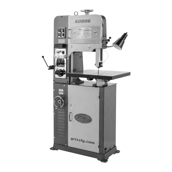
MODEL G0806/G0807
VARIABLE-SPEED VERTICAL
METAL-CUTTING BANDSAW
OWNER'S MANUAL
(For models manufactured since 12/15)
COPYRIGHT © FEBRUARY, 2016 BY GRIZZLY INDUSTRIAL, INC. REVISED JULY, 2017 (BL)
WARNING: NO PORTION OF THIS MANUAL MAY BE REPRODUCED IN ANY SHAPE
OR FORM WITHOUT THE WRITTEN APPROVAL OF GRIZZLY INDUSTRIAL, INC.
#BLJH17988 PRINTED IN TAIWAN
V2.07.17
Advertisement
Table of Contents


Need help?
Do you have a question about the G0806 and is the answer not in the manual?
Questions and answers