Table of Contents
Advertisement
Quick Links
Advertisement
Table of Contents

Summary of Contents for Kesla XS 190
- Page 1 SELF-PROPELLED TELESCOPIC PLATFORM OPERATION MAINTENANCE...
-
Page 2: Table Of Contents
Kesla ® SELF PROPELLED TELESCOPIC PLATFORM INTRODUCTION .........................4 TRANSPORT DIMENSIONS ....................5 LIFTING THE ACCESS PLATFORM WITH LIFTING HOOK ..........6 SPECIFICATION .........................7 TECHNICAL DATA ......................9 ACCESS PLATFORM XS190 BOOM GEOMETRY ............11 GENERAL SAFETY INSTRUCTIONS ................12 BEFORE USING THE ACCESS PLATFORM FOR THE FIRST TIME ......16 CHECKING THE OUTRIGGERS ...................17... - Page 3 Kesla ® SELF PROPELLED TELESCOPIC PLATFORM TRANSPORTING THE ACCESS PLATFORM ..............44 MAINTENANCE.........................45 PERIODIC MAINTENANCE...................45 MAINTENANCE SCHEME BASED ON OPERATING HOURS ........45 SERVICE PROGRAMME FOR DIESEL ENGINE .............46 KUBOTA D205E DIESEL ENGINE ................46 Starting and stopping the Kubota D905 Diesel engine ..........46 Kubota D905-E main service items................47...
- Page 4 Sealing........................68 REPAIRS ........................68 Welding........................68 Other repairs.......................69 Test loading (= overloading) ..................69 TERMS OF WARRANTY FOR KESLA XS ACCESS PLATFORMS .........70 WARRANTY COMPENSATION APPLICATION..............71 BILL OF DELIVERY......................72 WARRANTY ........................73 EU DECLARATION OF CONFORMITY FOR MACHINERY ..........74 REGISTRATION OF GUARANTEE OF KUBOTA ENGINE...........75 ACCESS PLATFORM INSPECTION JOURNAL ...............76...
-
Page 5: Introduction
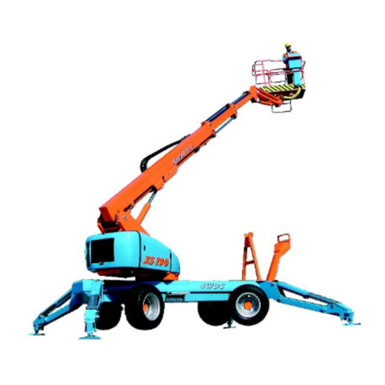
Kesla XS 190 is a self-propelled telescopic access platform provided with it own diesel engine or an optional 380V electric pump unit. XS 190 is intended for lifting personnel for instance in building and renovation sites, parks, and shipyards etc. Due its four-wheel drive and four-wheel steering, XS 190 is very agile, and can easily travel in difficult terrain when driven from the platform. -
Page 6: Transport Dimensions
Kesla ® SELF PROPELLED TELESCOPIC PLATFORM TRANSPORT DIMENSIONS... -
Page 7: Lifting The Access Platform With Lifting Hook
Kesla ® SELF PROPELLED TELESCOPIC PLATFORM LIFTING THE ACCESS PLATFORM WITH LIFTING HOOK Lifting the access platform with lifting hook... - Page 8 Kesla ® SELF PROPELLED TELESCOPIC PLATFORM SPECIFICATION FRONT...
-
Page 9: Specification
Kesla ® SELF PROPELLED TELESCOPIC PLATFORM Specification Platform Boom Turntable Turntable cover Combustion engine Drive and outrigger valve and jib rods Boom control valve, control from platform Boom control valve, control from below Chassis Front axle, rocker axle Front wheel and brakes... -
Page 10: Technical Data
Kesla ® SELF PROPELLED TELESCOPIC PLATFORM TECHNICAL DATA Max. height of platform bottom from ground ........16.7 m 54.8 ft. Max. working height ................18.7 m 61.4 ft. Min. lifting radius measured from the outer edge of the platform at max. working height ................. 1.0 m 3.3 ft. - Page 11 Kesla ® SELF PROPELLED TELESCOPIC PLATFORM Wide tyres.................... 350/50-16/12pr All-terrain tyres, high-traction tread ............10,0/75-15,3/8pr Max. noise level (at a distance of 1 m from the engine)....... 88 db Output of hydraulic pumpu @ 3000 rpm: for boom....................9.0 l/min 2.4 US.gpm from drive Diesel....................
-
Page 12: Access Platform Xs190 Boom Geometry
Kesla ® SELF PROPELLED TELESCOPIC PLATFORM ACCESS PLATFORM XS190 BOOM GEOMETRY 13.1 19.7 26.2 32.8ft. 59.1ft 16.7m 54.8ft. 52.5 8.0m 26.2ft. 14.0m 45.9 45.9ft. 13.0m 42.7ft. 39.4 9.2m 30.2ft 12.3m 32.8 40.4ft. =230kg 507lb 10.0 m 32.8ft. =120kg 264lb 26.2 =80kg 176lb 19.7... -
Page 13: General Safety Instructions
2. The operator must be at least 18 years of age and have reasonable operating experience of Access Platforms 3. Kesla XS 240 is fitted with the following fail-safe safety limit switches: Support position of the outriggers Ground sensing of outriggers... - Page 14 Kesla ® SELF PROPELLED TELESCOPIC PLATFORM 10. When operating the Access Platform, observe the adverse impact of wind, rain, temperature, thunder, bad visibility and accumulated snow and ice. 11. Do not take extra load while lifting, RISK OF TIPPING OVER! Do not leave the platform when it is up or when the Access Platform is moving.
- Page 15 Kesla ® SELF PROPELLED TELESCOPIC PLATFORM 25. Do not make or have made any structural alterations to the Access Platform without the permission and instructions of the manufacturer. 26. Do not open the filling opening of the cooling system if the engine is warm. Risk of an accident! 27.
- Page 16 Kesla ® SELF PROPELLED TELESCOPIC PLATFORM 6. You can get additional information about information related to batteries from these sources: Finnish regulations of electrical safety (Sähköturvallisuusmääräykset), chapter 21 Electrical card file (Sähkötietokortisto) cards No. TK 14.850, 14.855 Security instruction for fork trucks by insurance company Teollisuusvakuutus specifications for telecommunication networks 30.
-
Page 17: Before Using The Access Platform For The First Time
Kesla ® SELF PROPELLED TELESCOPIC PLATFORM BEFORE USING THE ACCESS PLATFORM FOR THE FIRST TIME Check the following always before using the Access Platform at the intervals stated in the table. DO NOT USE A FAULTY ACCESS PLATFORM. Daily Weekly... -
Page 18: Checking The Outriggers
Kesla ® SELF PROPELLED TELESCOPIC PLATFORM CHECKING THE OUTRIGGERS Check the functioning of the outrigger safety limits by extending the outriggers to the supporting position (wheels are off the ground). In this position, the boom can be operated. The outriggers have ground and position sensors; therefore a force of at least 6 kg (13,2 lbs) must be applied on the outriggers. - Page 19 Kesla ® SELF PROPELLED TELESCOPIC PLATFORM Check that the triangular fastening item on top on the boom is straight; visually check that the chains are tight. Note! If the triangular link is askew, in others words if one of the chains is shorter, check the condition, fastening and adjustment of the chains.
-
Page 20: Checking The Lifting Movement
Kesla ® SELF PROPELLED TELESCOPIC PLATFORM Checking the lifting movement Extend the jib to an angle of 45º with respect to the boom according to the markings at the end of the jib and the boom, see item C. Extend the jib all the way up, see fig. on page 19. Extend the boom extensions fully with the telescope. -
Page 21: Checking The Jib
Kesla ® SELF PROPELLED TELESCOPIC PLATFORM Checking the lifting radius platform Checking the lifting radius of the jib CHECKING THE JIB Support the Access Platform on the outriggers so that the wheels are about 100 mm off the ground. The platform must be empty. -
Page 22: Checking Of The Load Lowering Valves And The Boom Sections
Kesla ® SELF PROPELLED TELESCOPIC PLATFORM platform lever backup limit switch: is located on the right side of the boom, seen from the platform Checking: Start the Diesel engine for instance from the platform. Set a lever, for instance a wood stick as illustrated between the guide cam B and the cover. -
Page 23: Checking And Adjusting The Platform Load Control
Kesla ® SELF PROPELLED TELESCOPIC PLATFORM CHECKING ADJUSTING PLATFORM LOAD CONTROL mounting crank bearing grease nipples (8 nipples) locking bolt clearance adjusting screw weigher sensor control unit 8. Control unit Location of signal lamps in the control console. Signal lamp of max. platform load... -
Page 24: Operating Principle
Kesla ® SELF PROPELLED TELESCOPIC PLATFORM Operating principle The purpose of platform load control is to prevent the platform from being loaded in excess of the maximum permitted load (230 kg). When the platform load reaches the highest admitted load (230 kg), the max. platform load warning light lights. - Page 25 Kesla ® SELF PROPELLED TELESCOPIC PLATFORM Adjustment Open the platform-side door in the control panel. Switch on the power with the main power switch key. Load the platform with 230 kg according to the testing instruction. Adjust the point where the platform load signal lamp is switched on as follows.
-
Page 26: Failure Messages For The Platform Load Control
Kesla ® SELF PROPELLED TELESCOPIC PLATFORM Failure messages for the platform load control In case the platform load control fails, open the door of the control panel and check if there is one of the following failure messages in the display:... -
Page 27: Controls And Functions
Outrigger cylinder CONTROLS AND FUNCTIONS All controls of XS 190 are hydraulic; only outriggers are electrical. Also the safety limits of both the lowering of the telescope and the boom and the lifting of the jib operate electro- hydraulically. The various hydraulic movements have continuously variable speed adjustment. - Page 28 Kesla ® SELF PROPELLED TELESCOPIC PLATFORM The control levers and their symbols in the turntable 6-11 Levers 1, 2, 3 Lower control station (ground operation) Lever 1 Lever 2 Lever 3 Signal lamps and control equipment in the turntable Emergency lowering button...
- Page 29 Kesla ® SELF PROPELLED TELESCOPIC PLATFORM Warning lamps: Preheating Engine temperature Oil pressure Charging Warning lamp for the clogging of the return filter Warning lamp for the clogging of the pressure filter...
-
Page 30: The Control Equipment In The Platform
Kesla ® SELF PROPELLED TELESCOPIC PLATFORM THE CONTROL EQUIPMENT IN THE PLATFORM The control levers and their symbols in the platform Control levers from left to right Lifting/lowering and rotating the boom; push: the boom rises, pull: the boom lowers. -
Page 31: The Electric Controls In The Platform
Kesla ® SELF PROPELLED TELESCOPIC PLATFORM THE ELECTRIC CONTROLS IN THE PLATFORM The electric junction box in the platform: Emergency lowering button Horn (sound signal) Overload warning lamp; lights up when reaching the max. lifting radius Low fuel level warning lamp... -
Page 32: Driving/Outrigger Valves
Kesla ® SELF PROPELLED TELESCOPIC PLATFORM DRIVING/OUTRIGGER VALVES Lever operation decal Lever 1. Front left-hand outrigger up / down Lever 2. Front right-hand outrigger up / down Lever 3. Rear left-hand outrigger up / down Lever 4. Rear right-hand outrigger up / down Lever 5. -
Page 33: The Electric Control Box For The Drive / Outrigger Valve
Kesla ® SELF PROPELLED TELESCOPIC PLATFORM The electric control box for the drive / outrigger valve The electric control box for the valve rod system Function diagram decal... - Page 34 Kesla ® SELF PROPELLED TELESCOPIC PLATFORM Override buttons 1, 2, 3 When required, the boom may be lifted to an angle of approx. 20 degrees when the outriggers are up. This function increases the ground clearance at the platform for instance when driving the Access Platform on top of a trailer.
-
Page 35: Driving The Access Platform
SELF PROPELLED TELESCOPIC PLATFORM DRIVING THE ACCESS PLATFORM Kesla XS 190 has hydrostatic power train, and all the drive and control functions can be controlled from the platform. The power train has a continuous four-wheel drive and two speed ranges. The low speed range is 0 to 1.8 km/h with the pulling force measured from a stationary machine being 15,400 N;... -
Page 36: Driving Instructions
® SELF PROPELLED TELESCOPIC PLATFORM The driving hydraulics of Kesla XS 190 is equipped with a power distribution valve. The power distribution valve works as a differential lock by reducing the slipping of one wheel because of uneven friction between the wheels and the ground. Therefore it improves the off-road and climbing performance of the Access Platform. -
Page 37: Using The Outriggers And The Boom
Kesla ® SELF PROPELLED TELESCOPIC PLATFORM USING THE OUTRIGGERS AND THE BOOM Lower the outriggers to the supporting position and check the position with the levelling indicator. Maximum permitted erection inaccuracy is +1°. Check that all wheels are off the ground. -
Page 38: Erection Inclination
Kesla ® SELF PROPELLED TELESCOPIC PLATFORM ERECTION INCLINATION LATERAL INCLINATION WARNING! MAKE SURE THE ACCESS PLATFORM DOES NOT SLIP ON AN INCLINED SURFACE. WHEN REQUIRED, USE ADDITIONAL CALKS ON THE SOLE BOARDS OF THE OUTRIGGERS... -
Page 39: Soil Tightness Table
Kesla ® SELF PROPELLED TELESCOPIC PLATFORM SOIL TIGHTNESS TABLE M16x30 10.9 22500N 2300kg 5060lbs Maximum load on an outrigger sole Sole Surface are of the sole A: NOTE! (XS190 standard sole) otherwise A = 32,5 cm x 22 cm =715 cm2... -
Page 40: Using The Mains Voltage In The Platform
Kesla ® SELF PROPELLED TELESCOPIC PLATFORM USING THE MAINS VOLTAGE IN THE PLATFORM Connect the mains voltage 220V / 50Hz 16A to the outlet in the toolbox. In the platform, here are two grounded outlets for hand tools. The mains circuit is equipped with a ground fault interrupter (in the tool box) and a slip ring unit (inside the turntable). -
Page 41: Precautions When Moving From One Location To Another With The Boom
Kesla ® SELF PROPELLED TELESCOPIC PLATFORM PRECAUTIONS WHEN MOVING FROM ONE LOCATION TO ANOTHER WITH THE BOOM: WARNING ! watch up overhead high voltage cables do not touch electric cables do not damage the platform or the control equipment avoid damaging surrounding structures do not throw or let fall anything from the platform stay within the confines of the platform –... -
Page 42: Using The Emergency Lowering System
Kesla ® SELF PROPELLED TELESCOPIC PLATFORM USING THE EMERGENCY LOWERING SYSTEM DESIGN OF THE EMERGENCY LOWERING SYSTEM The emergency lowering system comprises an emergency lowering pump, the push- buttons for using the emergency lowering pump in the platform and at the ground control station, a platform control valve, a lower control valve, and the emergency lowering system instruction decals in the platform and at the turntable. -
Page 43: Location Of The Safety Limit Switches And The Electric Components42
Kesla ® SELF PROPELLED TELESCOPIC PLATFORM LOCATION OF THE SAFETY LIMIT SWITCHES AND THE ELECTRIC COMPONENTS The illustration above shows the location or the safety limit switches Outrigger limit switch, position limit switch, 4 switches Ground sensor limit switch, 4 switches... -
Page 44: Towing The Access Platform
Kesla ® SELF PROPELLED TELESCOPIC PLATFORM TOWING THE ACCESS PLATFORM Towing eye The Access Platform must be towed, if it gets stuck while being transferred. Tow the Access Platform by the towing eye located at the front or rear of the Access Platform. -
Page 45: Transporting The Access Platform
Kesla ® SELF PROPELLED TELESCOPIC PLATFORM For parking, anchor the Access Platform to a fixed object. R1/4” M8 x 60 R1/4” x 75 The illustration shows the brakes, the special nipple and the M8 bolt (all four wheels).(These are standard with the Access Platform.) TRANSPORTING THE ACCESS PLATFORM Do the following before transport. -
Page 46: Maintenance
Kesla ® SELF PROPELLED TELESCOPIC PLATFORM MAINTENANCE The Access Platform must be maintained regularly in order to keep it safe and efficient. For descriptions of the necessary service procedures, refer to the maintenance scheme and annual inspection list. If you feel uncertain about carrying out maintenance, do not hesitate to contact a service shop specialized in Access Platforms for the maintenance work and inspections needed. -
Page 47: Service Programme For Diesel Engine
Kesla ® SELF PROPELLED TELESCOPIC PLATFORM SERVICE PROGRAMME FOR DIESEL ENGINE KUBOTA D205E DIESEL ENGINE The diesel engine is Kubota D905E. The maximum speed of the engine has been adjusted to approx. 2700 rpm. This speed should not be exceeded. The top speed is needed when driving in difficult terrain. When adjusting the engine speed, 1500 rpm should be considered as the minimum level. -
Page 48: Kubota D905-E Main Service Items
Kesla ® SELF PROPELLED TELESCOPIC PLATFORM Kubota D905-E main service items Kubota D905-E Engine oil filler Oil filter Oil drain hole Oil level dipstick Speed regulator Stopping solenoid... -
Page 49: Kubota D905-E Service Programme
Kesla ® SELF PROPELLED TELESCOPIC PLATFORM Kubota D905-E service programme Kubota D905-E Daily, Check oil; check for leakages, correct as required before use. with the engine Check level and cleanliness of oil. Add oil when required. switched off: Check coolant level. NOTE! DO NOT OPEN THE FILLING OPENING OF THE COOLING WATER SYSTEM IF THE ENGINE IS WARM. -
Page 50: Kubota D905-E Changing The Oil Filter And Oil
Kesla ® SELF PROPELLED TELESCOPIC PLATFORM KUBOTA D905-E changing the oil filter and oil Changing the oil filter and oil of KUBOTA D905-E Changing the engine oil Draining hose Draining plug Open and remove the hood sections. Bend the engine oil draining hose between the turntable and the chassis to the side of the chassis. -
Page 51: Lubrication Diagram
Kesla ® SELF PROPELLED TELESCOPIC PLATFORM Fasten an oil filter tool on the filter and turn CCW. Apply a thin coating of new oil to the rubber gasket and turn until the rubber gasket contacts the adapter. Then tighten additional 1/2 turns. -
Page 52: Selection Of Lubricants, Oil Volumes
Kesla ® SELF PROPELLED TELESCOPIC PLATFORM SELECTION OF LUBRICANTS, OIL VOLUMES Diesel engine: Kubota D905-E : Oil volume.................... 5.1 ltr with filter SAE 30 or SAE10W-30, SAE10W-40 ..........over +25°C SAE 20 or SAE10W-30, SAE10W-40 ..........0°C to +25°C SAE 10W or SAE10W-30, SAE10W-40..........below 0°C Hydraulic system Oil volume.................... -
Page 53: Checking The Hydraulic Oil, Adding Oil
Kesla ® SELF PROPELLED TELESCOPIC PLATFORM CHECKING THE HYDRAULIC OIL, ADDING OIL Check the hydraulic oil level with the boom on the transport support, the telescope fully retracted, and all outriggers fully up. Remove the left-hand side cover over the turntable, seen from the platform. -
Page 54: Maintenance Of Driving Brakes
SELF PROPELLED TELESCOPIC PLATFORM MAINTENANCE OF DRIVING BRAKES CONSTRUCTION OF BRAKES Kesla XS 190 has driving brakes both in front and rear axles, located in the wheel hubs. Disk brakes are opened by hydraulic pressure. When the pressure of the drive motor exceeds 30 bar, the disk brakes open, and a spring automatically closes the brakes when the pressure drops below 30 bar. -
Page 55: Changing The Brake Pads
Kesla ® SELF PROPELLED TELESCOPIC PLATFORM CHANGING THE BRAKE PADS 1. Change the brake pad if the thickness of the friction surface is less than 1.5mm (0.06in). R1/4” M8 x 60 R1/4” x 75 Drive the Access Platform on an even and firm ground. -
Page 56: Brake Cylinder
Kesla ® SELF PROPELLED TELESCOPIC PLATFORM BRAKE CYLINDER Min 1,5 (wear surface) 0,06 in 0.06 in Brake cylinder BOOM CHAINS – ADJUSTMENT AND MAINTENANCE INSTRUCTION FOR INSPECTION Retract the boom completely with the telescope cylinder. Position of the outermost boom section: Check clearance A. See illustration on page 56. -
Page 57: Adjusting The Chain Tension
Kesla ® SELF PROPELLED TELESCOPIC PLATFORM Replace the chains of there is visible wear, cracks or deformed side plates. Check also the condition of the chain ends. Adjusting the boom chains ADJUSTING THE CHAIN TENSION Support the Access Platform on the outriggers with the wheels slightly off the ground. -
Page 58: Torque Scheme For Bolts And Nuts
Kesla ® SELF PROPELLED TELESCOPIC PLATFORM When the chains are hanging freely, the distance between the chain and the boom in the middle of the chain should be approx. 10mm (0.39in). For adjustment and inspection, the chains should be made loose with a reverse movement. -
Page 59: Torques If Not Otherwise Mentioned
Kesla ® SELF PROPELLED TELESCOPIC PLATFORM TORQUES IF NOT OTHERWISE MENTIONED Prelimary torque for screws with metric Prelimary torque for screws with metric ISO thread Nm ISO fine thread Nm 10.9 12.9 10.9 12.9 M8 x 1 24,5 34,3 40,2... -
Page 60: Checking The Play Of The Slewing Mechanism
Kesla ® SELF PROPELLED TELESCOPIC PLATFORM CHECKING THE PLAY OF THE SLEWING MECHANISM PIVOT POINT Retract the boom completely, lower the jib. Lower the transport support, leave the boom in horizontal position. Push the platform lightly from direction B –remove the free play. Measure dimension L1. -
Page 61: Checking The Torque Of The Slewing Gear Bolts
Kesla ® SELF PROPELLED TELESCOPIC PLATFORM CHECKING THE TORQUE OF THE SLEWING GEAR BOLTS BOLTS OF PIVOT BEARING, INNER CIRCLE Remove the front cover of the turntable. Check torque using a torque wrench, correct value 270Nm. M16x90 bolts, initial torque 280Nm... -
Page 62: Repairs And Alterations Affecting Strength, Stability, And Performance
Kesla ® SELF PROPELLED TELESCOPIC PLATFORM REPAIRS AND ALTERATIONS AFFECTING STRENGTH, STABILITY, AND PERFORMANCE If the owner needs to perform repairs or alterations, which affect the structural strength, stability and performance, he should devise a plan for these works and have it approved of by the manufacturer in advance. -
Page 63: After A Long-Term Storage
Kesla ® SELF PROPELLED TELESCOPIC PLATFORM AFTER A LONG-TERM STORAGE Clean the piston rods and the load control linkage. Check engine oil and coolant levels, add as required. Reinstall the battery. Start the Access Platform, let the engine idle for a moment. -
Page 64: Instructions For Re-Inspections
INSTRUCTIONS FOR RE-INSPECTIONS Inspecting the Access Platform Kesla XS 190 should be inspected in accordance with these instructions at least once a year or more frequently when needed. The inspection interval must nut exceed 12 months from the commissioning of the Access Platform. -
Page 65: Warning Plate
Kesla ® SELF PROPELLED TELESCOPIC PLATFORM The equipment weight 70kg(154lbs) and the maximum lateral load 400N (40kg/88lbs) are shown in the load plate. Another load plate is located next the control valve at the ground control station. Warning plate The following warning plates can be found in the ground control station and in the platform. -
Page 66: Safety Requirements
The boom is in the transport position also when both the control levers of drive/outrigger valve and bypass buttons are within the reach of the operator. XS 190 has limit switches for the positions of the outriggers and ground sensor limit switches. The position sensor is activated, when the outriggers have been turned at least 30°... -
Page 67: Emergency Lowering System
Kesla ® SELF PROPELLED TELESCOPIC PLATFORM If a hose is damaged, the working platform must be kept locked by the hydraulic stabilizing equipment. The hydraulic stabilizing equipment is fitted with a lock valve. The horizontal level of the platform can be corrected with a control lever located in the boom control valve. -
Page 68: Working Platform
Kesla ® SELF PROPELLED TELESCOPIC PLATFORM Working platform Fixing equipment Locking of joints Tears and other damage Condition and automatic closing of the gate Access routes and railings Outriggers Wear Corrosion damage Welded joints Transport position Rack for boom transport position... -
Page 69: Symbols
Kesla ® SELF PROPELLED TELESCOPIC PLATFORM Symbols The movement directions and the analogies between the control levers and the platform movements are shown with decals. Replace a damaged or unreadable decal with a new one, which can be purchased from the manufacturer. -
Page 70: Other Repairs
Kesla ® SELF PROPELLED TELESCOPIC PLATFORM Other repairs Any other repairs of the load-bearing structures (e.g. cylinder) must also be entered in the inspection journal under "Remarks", including the following information: Location of the repair Date Name of the person who carried out the repair Make sure that the manufacturer's instructions have been observed. -
Page 71: Terms Of Warranty For Kesla Xs Access Platforms
Should the warranty claim concern a defective part, already removed from the Access Platform, that is to be replaced with a corresponding faultless part, the replacement shall take place free of charge at the spare part store of Kesla Oyj or an authorised maintenance shop. -
Page 72: Warranty Compensation Application
________________________________________________________________________ WORKING HOURS OF ACCESS PLATFORM WHEN THE DAMAGE OCCURRED_____ Damage date (d/m/y)___/___200___Repaired on (d/m/y) ___/___200_______________ Repaired by ___________________ Job No.___________________________________ The damaged parts have been returned to Kesla Oyj. Shipment date____/____200________________________________________________ Method of delivery________________________ Delivered from____________________ Freight bill No.____________________________________________________________... -
Page 73: Bill Of Delivery
Kesla® XS 190 Serial number ______________________Owner________________________________ Accessories________________________Street address__________________________ _________________________________ Postal code and town_____________________ _________________________________Telephone______________________________ __________________________________Seller_________________________________ .-------------------------------------------------------------------------------------------------------------------- To be returned to: KESLA OYJ Metsolantie 2 59800 KESÄLAHTI Tel. +358 13 682841 Fax. +358 13 6828100 BILL OF DELIVERY Commissioning date (d/m/y):_____/_____200____ Kesla®... -
Page 74: Warranty
Kesla ® SELF PROPELLED TELESCOPIC PLATFORM WARRANTY _______/______200_________ SERIAL NUMBER______________________________________________________________ SELLER:______________________________________________________________... -
Page 75: Eu Declaration Of Conformity For Machinery
Tel. (013) 682841 Fax. (013) 6828100 herewith declares that Self-Propelled Telescopic Platform Kesla XS 190 serial number_____________ is in conformity with the provisions of the Machine Directive 98/37/EEC, 89/336/EEC as amended and with national implementing legislation (Council of State Decision on machine safety Vnp 1314/94). -
Page 76: Registration Of Guarantee Of Kubota Engine
To ensure that the warranty of the Kubota engine starts on the commissioning date of the machine, please complete the below form and forward it by e-mail, post or fax to the address given below. Commissioning date (d/m/y): ______/_______200___ Kesla® XS 190 ENGINE TYPE: KUBOTA D905 MANUFACTURING NUMBER:________________ SERIAL NUMBER:_D905... -
Page 77: Access Platform Inspection Journal
Type of MEWB: BP Boom platform Boom: TB Telescope boom Chassis: MS MEWP (self-propelled) Outriggers: HT Hydraulic turning TECHNICAL DATA Model and type: Kesla XS 190 Max. height of platform HP= 16,7 m Serial No. / Manuf.year:________________ Max. side outreach SO=8.0m /230Kg... -
Page 78: Access Platform Inspection Journal
Kesla ® SELF PROPELLED TELESCOPIC PLATFORM ACCESS PLATFORM INSPECTION JOURNAL (Fill this journal carefully. Keep the journal with the Access Platform for at least two years) RE-INSPECTION (= maintenance check) Date (d/m/y). _______/ _________ 20____ Place of inspection ___________________ Inspected by_________________________... -
Page 79: Access Platform Inspection Journal
Kesla ® SELF PROPELLED TELESCOPIC PLATFORM ACCESS PLATFORM INSPECTION JOURNAL (Fill this journal carefully. Keep the journal with the Access Platform for at least two years) RE-INSPECTION (= maintenance check) Date (d/m/y). _______/ _________ 20____ Place of inspection ___________________ Inspected by_________________________... -
Page 80: Access Platform Inspection Journal
Kesla ® SELF PROPELLED TELESCOPIC PLATFORM ACCESS PLATFORM INSPECTION JOURNAL (Fill this journal carefully. Keep the journal with the Access Platform for at least two years) RE-INSPECTION (= maintenance check) Date (d/m/y). _______/ _________ 20____ Place of inspection ___________________ Inspected by_________________________... -
Page 81: Access Platform Inspection Journal
Kesla ® SELF PROPELLED TELESCOPIC PLATFORM ACCESS PLATFORM INSPECTION JOURNAL (Fill this journal carefully. Keep the journal with the Access Platform for at least two years) RE-INSPECTION (= maintenance check) Date (d/m/y). _______/ _________ 20____ Place of inspection ___________________ Inspected by_________________________... -
Page 82: Access Platform Inspection Journal
Kesla ® SELF PROPELLED TELESCOPIC PLATFORM ACCESS PLATFORM INSPECTION JOURNAL (Fill this journal carefully. Keep the journal with the Access Platform for at least two years) RE-INSPECTION (= maintenance check) Date (d/m/y). _______/ _________ 20____ Place of inspection ___________________ Inspected by_________________________... - Page 83 Kesla ® SELF PROPELLED TELESCOPIC PLATFORM...
Need help?
Do you have a question about the XS 190 and is the answer not in the manual?
Questions and answers