Table of Contents
Advertisement
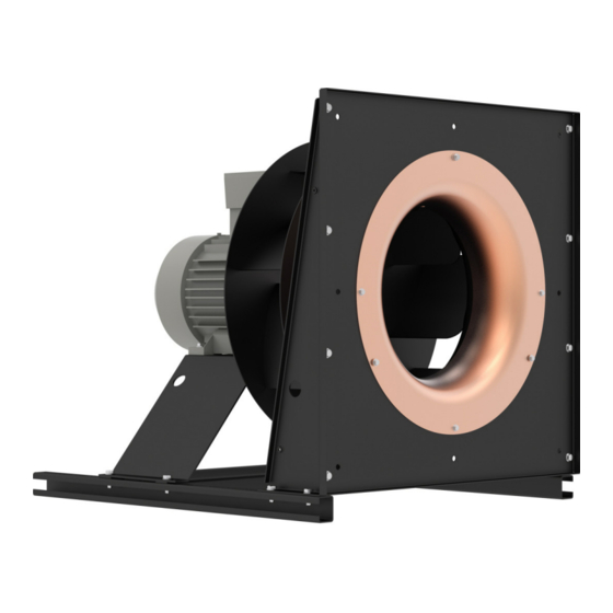
RH..C and ER..C
RH..C radial impellers and ER..C plug fans in explosion proof
design in compliance with Directive 2014/34/EU (ATEX).
Directly powered with IEC standard motor for use in
explosive atmospheres, zone 1 (category 2) and zone 2
(category 3).
Assembly instructions
L-BAL-F019-GB 2021/12 Index 003
Keep for reference!
VENTILATOR-Typenschild
einkleben!
Part.-No. 00282064-GB
english
Advertisement
Table of Contents

Related Manuals for ZIEHL-ABEGG ER25C


Summary of Contents for ZIEHL-ABEGG ER25C
- Page 1 english RH..C and ER..C RH..C radial impellers and ER..C plug fans in explosion proof design in compliance with Directive 2014/34/EU (ATEX). Directly powered with IEC standard motor for use in explosive atmospheres, zone 1 (category 2) and zone 2 (category 3). Assembly instructions Keep for reference! VENTILATOR-Typenschild...
-
Page 2: Table Of Contents
Assembly instructions RH..C and ER..C Content General notes ..........Scope of documentation . - Page 3 Assembly instructions RH..C and ER..C 4.2.4 Sealing ........Assembly of ER..C plug fans .
- Page 4 Assembly instructions RH..C and ER..C EC Declaration of Incorporation ......EU declaration of conformity ......Index .
-
Page 5: General Notes
Assembly instructions RH..C and ER..C General notes 1 General notes Compliance with the following instructions is mandatory to ensure the functionality and safety of the product. If the following instructions given especially but not limited for general safety, transport, storage, mounting, operating conditions, start-up, mainte- nance, repair, cleaning and disposal / recycling are not observed, the product may not operate safely and may cause a hazard to the life and limb of users and third parties. -
Page 6: Target Group
We do not accept any liability for possible errors or omissions in the information con- tained in data, illustrations or drawings provided. ZIEHL-ABEGG SE is not liable for damage due to misuse, improper use or as a consequence of unauthorized repairs or modifications. - Page 7 Assembly instructions RH..C and ER..C Safety • Start-up and maintenance of the device may only be carried out by skilled personnel, who have completed ATEX training for correct performance of their work. • The motor overheating protection equipment must be connected. Improper con- nection will invalidate the manufacturer's warranty.
-
Page 8: Intended Use
Observe the permissible temperature classes on the rating plate. • Due to their safe design, ZIEHL-ABEGG ER...C plug fans from Group II, Category 2G, 3G for gas with ignition protection type "h" ("c") are suitable for conveying Group IIA and IIB explosive atmospheres for Zone 1 and Zone 2. -
Page 9: Improper Use / Reasonably Foreseeable Misuse
Assembly instructions RH..C and ER..C Safety • Release of an explosive atmosphere from the inside to the outside or from the outside to the inside, thus resulting in an explosive atmosphere (zone entrainment). • The following sections explain additional risks and the required measures to minimise or avoid them. -
Page 10: Explanations Of Symbols
Assembly instructions RH..C and ER..C Safety – Only the following components may be fastened to the fan: Air flow components (expansion joints for pipes or ductwork), loose accessories supplied, parts for the drive motor electrical connection. The fan may only be connected to pipes or a ductwork system using an expansion joint. -
Page 11: Requirements Placed On The Personnel / Due Diligence
Assembly instructions RH..C and ER..C Safety The design and installation of the system must comply with local regulations and directives. 2.6 Requirements placed on the personnel / due diligence Persons entrusted with the planning, installation, commissioning and maintenance and servicing in connection with the frequency inverter must have the corresponding qual- ifications and skills for these jobs. -
Page 12: Modifications / Interventions In The Device
ZIEHL-ABEGG.These parts were specifically designed for the device. There is no guarantee that parts from non-original sources are designed and manufactured in correspondence with load and safety requirements. Parts and optional equipment not supplied by ZIEHL-ABEGG are not approved by ZIEHL-ABEGG for use. 2.9 Operator’s obligation of diligence •... -
Page 13: Product Overview
Assembly instructions RH..C and ER..C Product overview 3 Product overview 3.1 Application / operational area The free running radial impellers from the RH..C series, available in frame sizes 250 to 1000, and the ER..C series (see rating plate for type designation) in explosion proof design II 2G Ex h IIB T4 Gb with IEC standard motor in ignition protection class Ex d IIC/IIB T4 Gb, Ex de IIC/IIB T4 Gb, Ex db IIC/IIB T4 Gb and Ex db eb IIC/IIB T4... -
Page 14: Fan Marking
Assembly instructions RH..C and ER..C Product overview According to EN ISO 80079-36 the following correlation exists between the temperature class and the maximum surface temperature: Temperature class Max. surface temperature 450 °C 300 °C 200 °C 135 °C 100 °C 85 °C 3.1.5 Fan marking Example for marking of an ER..C plug fan:... -
Page 15: Transport, Storage
Assembly instructions RH..C and ER..C Product overview 3.3 Transport, storage Attention! • Wear safety clothing / shoes and cut-resistant safety gloves when handling. • Avoid shocks and impacts to the device during the transport. • Avoid extreme humidity, heat or exposure to cold (see technical data). •... -
Page 16: Mounting
In terms of material selection, due to special protective measures relating to possible contact surfaces between rotating and stationary components (impeller / inlet nozzle), ZIEHL-ABEGG ER..C plug fans satisfy the requirements of the EN 14986 standard. Steel plate (coated) is used as the material for the rotating component (impeller). If the impeller is purchased without a ZIEHL-ABEGG inlet nozzle, the system manufacturer is responsible for selecting the material for the stationary peripheral parts. -
Page 17: Installation, Protection From External Influences
The fan should be mounted on suitable vibration dampers. These are available as accessories from ZIEHL-ABEGG. Pipes and ductwork may only be connected via elastic connections (expansion joints), which are available as accessories. When purchasing expansion joints that are not supplied by ZIEHL-ABEGG, the system manufacturer must ensure that they comply with Directive 2014/34/EU or that they have corresponding type examination certificates. - Page 18 456.8 ER/RH80C 514.9 ER/RH90C 580.2 ER/RH10C 625.5 The possible contact diameter corresponds to the internal diameter at the suction mouth of the impeller, which is specified on ZIEHL-ABEGG SE dimension sheets as “DE”. L-BAL-F019-GB 2021/12 Index 003 Part.-No. 00282064-GB 18/48...
-
Page 19: Sealing
4.4 Special instructions on the installation of series fans ER..C ZIEHL-ABEGG ER..C series plug fans are generally installed in customer air condition- ing and ventilation systems and can only be classed as complete and functioning fans when installed correctly in the customer systems. - Page 20 Since in this series ZIEHL-ABEGG SE does not have any influence itself over the installation conditions of the supplied fan, the customer or system manufacturer is...
-
Page 21: Mounting Rh
Assembly instructions RH..C and ER..C Mounting Attention! ER..C plug fans may only be operated in installation position H (fan upright, motor shaft horizontal). 4.5 Mounting RH..C Attention! Whenever working on a fan, under no circumstances loosen the bolts that hold the impeller to the hub! Impeller and hub together form a balanced module which may only be removed and fitted as a complete unit. -
Page 22: Connection Of Pipes
Assembly instructions RH..C and ER..C Mounting Tightening torques for screw connections with shaft screws combined with contact washers (protective conductor system) with associated nuts (μges.=0.16) in Nm: Property class 8.8 (Steel) 11.3 27.4 4.6 Connection of pipes • Tensions on the fan by pipe connections must be avoided. These can lead to contact between rotating and stationary parts. -
Page 23: Electrical Installation
Assembly instructions RH..C and ER..C Electrical installation 5 Electrical installation 5.1 Safety precautions Danger due to electric current • Work on electric components may only be carried out by trained electricians or by persons instructed in electricity under the supervision of an electrician in accordance with electrical engineering regulations. -
Page 24: Frequency Inverter And Emc
• When operating on the inverter harmful bearing currents can occur in the motor. This depends on many factors which, in many cases, ZIEHL-ABEGG cannot influence. Thus, it comes down to the expert installation in the respective assembly situation. The following points serve as a guideline, but cannot always prevent bearing currents from occurring. -
Page 25: Electrical Connection, Grounding And Protection
Assembly instructions RH..C and ER..C Electrical installation • If the cable shield cannot be contacted or not contacted sufficiently due to special framework conditions, use a separate high-frequency equipotential bonding conduc- tor between the motor housing and the protective earth bar of the inverter. –... -
Page 26: Mains Connection
The motors have triplet PTC’s. More than two PTC’s may not be connected in series, as this can lead to undefined shut-downs. • PTC thermistor release unit, e.g. ZIEHL-ABEGG type U-EK230E with disconnection via a contactor. • A current dependent protection is not admissible and also not possible as secondary protection. -
Page 27: During Start-Up Check The Following
Check the system for resonances. If they lead to unacceptably high vibrations on the fan, the system may not be started up. If necessary, contact ZIEHL-ABEGG SE service and observe the table of resonant frequencies for ER..C fans in Chapter 6.3. - Page 28 Assembly instructions RH..C and ER..C Start-up In addition, perform the following tests before switching on an explosion-pro- tected fan: • Check the operating conditions / process parameters (see “Intended use”). Above all, it is essential to ensure that the maximum permitted values for speed, suction and ambient temperature (see rating plate) are not exceeded under any circumstances and at any time.
- Page 29 For each speed listed, a tolerance of +/- 60 rpm applies. Example: Speed range to be blocked for ER25C-2DY.B7.1R with 0.75 kW motor: 1770 +/- 60 rpm and 2742 +/- 60 rpm => This fan may not be operated in the speed ranges 1710 - 1830 rpm and 2682 - 2802 rpm.
- Page 30 Assembly instructions RH..C and ER..C Start-up Motoren IE2 fan type Power Speeds to be blocked; tolerance +/- 60 rpm [kW] [1/min] ER35C-2DY.F7.1R 2964 ER40C-4DY.D7.1R ER40C-4DY.D7.1R ER40C-4DY.E7.1R 1542 ER40C-4DY.E7.1R 1152 ER40C-2DY.F7.1R 2646 ER40C-2DY.G7.1R 2568 ER45C-4DY.D7.1R ER45C-4DY.D7.1R ER45C-4DY.E7.1R ER45C-4DY.E7.1R 1452 ER45C-4DY.F7.1R 1116 ER45C-4DY.G7.1R 2550 ER45C-2DY.G7.1R...
- Page 31 Assembly instructions RH..C and ER..C Start-up Motoren IE2 fan type Power Speeds to be blocked; tolerance +/- 60 rpm [kW] [1/min] ER63C-4DY.G7.1R ER63C-4DY.H7.1R ER63C-4DY.I7.1R 1338 ER63C-4DY.K7.1R 1116 ER71C-6DY.F7.1R ER71C-6DY.G7.1R ER71C-6DY.H7.1R ER71C-6DY.H7.1R ER71C-4DY.H7.1R ER71C-4DY.I7.1R ER71C-4DY.K7.1R 1758 ER71C-4DY.L7.1R 18.5 ER80C-6DY.H7.1R ER80C-6DY.H7.1R ER80C-6DY.I7.1R ER80C-6DY.K7.1R ER80C-4DY.K7.1R ER80C-4DY.L7.1R...
- Page 32 Speeds to be blocked; tolerance +/- 60 rpm [kW] [1/min] ER10C-6DY.R7.1R ER10C-6DY.S7.1R Fans with IE3 Motoren Motoren IE3 fan type Power Speeds to be blocked; tolerance +/- 60 rpm [kW] [1/min] ER25C-2DY.B7.1R 0.75 1770 2742 ER25C-2DY.B7.1R ER25C-2DY.D7.1R 2918 1980 ER25C-2DY.D7.1R 2870 ER28C-2DY.B7.1R 0.75 1980 ER28C-2DY.B7.1R...
- Page 33 Assembly instructions RH..C and ER..C Start-up Motoren IE3 fan type Power Speeds to be blocked; tolerance +/- 60 rpm [kW] [1/min] ER45C-4DY.D7.1R 1452 ER45C-4DY.D7.1R ER45C-4DY.E7.1R ER45C-4DY.E7.1R 1452 ER45C-4DY.F7.1R 1116 ER45C-4DY.G7.1R 2550 ER45C-2DY.G7.1R ER50C-4DY.D7.1R ER50C-4DY.E7.1R ER50C-4DY.E7.1R ER50C-4DY.F7.1R ER50C-4DY.G7.1R ER50C-4DY.H7.1R 2220 ER50C-4DY.I7.1R 1368 2683 ER56C-6DY.E7.1R...
- Page 34 Assembly instructions RH..C and ER..C Start-up Motoren IE3 fan type Power Speeds to be blocked; tolerance +/- 60 rpm [kW] [1/min] ER71C-6DY.H7.1R ER71C-4DY.H7.1R ER71C-4DY.I7.1R ER71C-4DY.K7.1R 1758 ER71C-4DY.L7.1R 18.5 ER80C-6DY.H7.1R ER80C-6DY.H7.1R ER80C-6DY.I7.1R ER80C-6DY.K7.1R ER80C-4DY.K7.1R ER80C-4DY.L7.1R 18.5 1524 ER80C-4DY.M7.1R ER90C-8DY.I7.1R ER90C-8DY.I7.1R ER90C-6DY.I7.1R ER90C-6DY.K7.1R ER90C-6DY.M7.1R ER90C-6DY.N7.1R...
-
Page 35: Trouble Shooting
Assembly instructions RH..C and ER..C Trouble shooting 7 Trouble shooting 7.1 Code of behaviour in the event of faults In the event of faults, which represent a danger to people, installation or environment, " the fan must be switched off. Search for the cause of the error. - Page 36 Check wings/blades for damage, soiling or ice see "Impeller blocked or dirty" Unusual noises Ball bearing damaged / Replacement of the ball bearing by ZIEHL-ABEGG re- worn quired Impeller / blade scrapes / When indicated, clear foreign bodies/dirt from the fan brushes see "Impeller blocked or dirty"...
-
Page 37: Service Work
• Bolted-on impellers and/or wings may only be replaced by authorised ZIEHL-ABEGG SE staff. The manufacturer shall not be liable for damage caused through improper repair work. • In the case of complete dismantling and reinstallation of the fan, checking must be carried out before start-up (see start-up). -
Page 38: Particularities When Using In Explosive Atmospheres
Be aware of the following Points: • ZIEHL-ABEGG recommends that during the phase of commissioning of a new fan, a visual inspection during which the fan is especially checked for the tight seating of all bolted connections, dirt, vibrations and unusual noises is undertaken at least weekly. -
Page 39: Bolted Connections And Ground Connections
Assembly instructions RH..C and ER..C Service work 8.2.1 Bolted connections and ground connections During all mounting/installation work, make sure that contact disks are always used for the bolted connections of coated components which come into contact with explosive atmospheres in order to electrically connect all components conductive with each other, to completely maintain potential equalisation. -
Page 40: Load-Bearing Parts
Assembly instructions RH..C and ER..C Service work 8.2.4 Load-bearing parts Load bearing parts (motor bed, nozzle supporting plate with fastening brackets, profile rails) must be checked for contamination, damage and deformation and should be cleaned, repaired or replaced as required. 8.2.5 Clearances and gap dimension Before reconnection of the fan after maintenance work, proceed as described in the Commissioning chapter. -
Page 41: Enclosure
Assembly instructions RH..C and ER..C Enclosure 9 Enclosure 9.1 Technical data Line voltage see Fan-rating plate Switching frequency Fans are rated for S1 continuous operation. Controls must not allow extreme switching operation! Permissible minimal and maxi- mal ambient temperature for op- -20 ...40 °C bzw. - Page 42 Electronically commutated internal or external rotor motor (also with integrated EC controller) complies with the requirements in Appendix I, Articles 1.1.2, 1.1.5, 1.4.1, 1.5.1 in EG Machinery Directive 2006/42/EG. The manufacturer is ZIEHL-ABEGG SE Heinz-Ziehl-Strasse D-74653 Künzelsau The following harmonised standards have been used: EN 60204-1:2006 + A1:2009 + Safety of machinery;...
- Page 43 It is prohibited to commission this incomplete machine until it has been secured that the machine into which it was incorporated complies with the stipulations of the EC Machinery Directive. Künzelsau, 28.10.2020 (location, date of issue) ZIEHL-ABEGG SE ZIEHL-ABEGG SE Dr. W. Angelis Dr. D. Kappel Head of Technics Ventilation Technology...
- Page 44 Assembly instructions RH..C and ER..C Enclosure EU declaration of conformity - Translation - (english) ZA152ex-GB 2007 Index 002 ZIEHL-ABEGG SE Heinz-Ziehl-Straße 74653 Künzelsau Germany The manufacturer hereby declares its sole responsibility that the products • Axial fan: FB…., FV…., DN….
- Page 45 Assembly instructions RH..C and ER..C Enclosure Type Zone Equip- Type of Explosion Temperature Equipment ment protec- group* class* protection class tion level EPL Centrifugal Fan RH... 1 h, (c) IIA, IIB T1,T2,T3,(T4) Gb Centrifugal Fan RH... 2 h, (c) IIA, IIB T1,T2,T3,(T4) Gc T 125 °C Centrifugal Fan...
- Page 46 (e.g. control units, guard grilles, etc.), then the manufacturer or operator of the complete system is responsible for compliance with the ATEX Directive 2014/34/EU. Künzelsau, 25.02.2020 (location, date of issue) ZIEHL-ABEGG SE ZIEHL-ABEGG SE Dr. W. Angelis Dr. D. Kappel...
- Page 47 Assembly instructions RH..C and ER..C 9.4 Index air density ignition temperature Assembly Imbalance ATEX ATEX Zone 12, 23 linevoltage Ball bearing bearing mains connection material combinations capacitor charges overheating protection cleaning process equipment cold greasing construction painting potential equalisation direction of rotation protective devices dismantling Technical data...
- Page 48 9.5 Manufacturer reference Our products are manufactured in accordance with the relevant international regulations. If you have any questions concerning the use of our products or plan special uses, please contact: ZIEHL-ABEGG SE Heinz-Ziehl-Straße 74653 Künzelsau phone: +49 (0) 7940 16-0 info@ziehl-abegg.de...
Need help?
Do you have a question about the ER25C and is the answer not in the manual?
Questions and answers