Table of Contents
Advertisement
Quick Links
DIGITAL MIXING CONSOLE
Owner's Manual
1
2
3
4
PAD
26dB
26dB
26dB
26dB
–16
–60
–16
–60
–16
–60
–16
–60
–16
+10
GAIN
–34
+10
GAIN
–34
+10
GAIN
–34
+10
GAIN
–34
+10
SETUP
SCENE
MIDI
MEMORY
UTILITY
MIDI
REMOTE
DIO
GROUP/PAIR
SOLO SETUP
AUTOMIX
CHANNEL CONTROL
DELAY/Ø
DYNAMICS
PAN/ROUTING
VIEW
EQ LOW
LO-MID
HI-MID
HIGH
EQ LIBRARY
EQ FLAT
FADER MODE
AUX 1
AUX 2
AUX 3
AUX 4
FADER
EFFECT 1
EFFECT 2
METER
MIXING LAYER
1–16
17–24/MASTER
1
2
3
4
17
18
19
20
SEL
SEL
SEL
SEL
ON
ON
ON
ON
6
6
6
6
6
0
0
0
0
0
5
5
5
5
5
10
10
10
10
10
20
20
20
20
20
40
40
40
40
40
60
60
60
60
60
00
00
00
00
00
1
2
3
4
17
18
19
20
5
6
7
8
9
26dB
26dB
26dB
26dB
–60
–16
–60
–16
–60
–16
–60
+10
+10
–20
GAIN
–34
+10
GAIN
–34
+10
GAIN
–34
+10
GAIN
–34
GAIN
SCENE MEMORY
FUNCTION
SEL CH
FADER
STATUS
FADER 1–8
9–12
13–16
5
6
7
8
9
21
22
23
24
AUX1
AUX2
SEL
SEL
SEL
SEL
SEL
ON
ON
ON
ON
ON
6
6
6
6
6
0
0
0
0
0
5
5
5
5
5
10
10
10
10
10
20
20
20
20
20
40
40
40
40
40
60
60
60
60
60
00
00
00
00
00
5
6
7
8
9
21
22
23
24
AUX1
AUX2
10
11
12
13
14
+10
+10
–20
+10
+10
–20
+10
+10
–20
+10
+10
–20
+10
+10
–20
+10
+10
GAIN
GAIN
GAIN
GAIN
GAIN
USER DEFINE
L STEREO R
CLIP
–3
–6
–9
–12
–15
–18
–24
–30
–36
–42
–48
ST IN
EFFECT RTN
10
11
12
13
14
AUX3
AUX4
BUS1
BUS2
BUS3
SEL
SEL
SEL
SEL
SEL
SEL
ON
ON
ON
ON
ON
6
6
6
6
6
0
0
0
0
0
5
5
5
5
5
10
10
10
10
10
20
20
20
20
20
40
40
40
40
40
60
60
60
60
60
00
00
00
00
00
10
11
12
13
14
AUX3
AUX4
BUS1
BUS2
BUS3
PHONES
15
16
ST IN
MONITOR
PHONES
OUT
SOLO/
2TR IN
–20
+10
+10
–20
+10
+10
–20
0
10
0
10
GAIN
GAIN
GAIN
LEVEL
LEVEL
SCENE MEMORY
SOLO
UNDO/
REDO
SOLO
STORE
RECALL
USER DEFINE
1
2
PARAMETER
3
4
ENTER
CURSOR
1
2
15
16
EFFECT
ST IN
ST OUT
RETURN
BUS4
SEL
SEL
SEL
SEL
ON
ON
ON
ON
ON
6
6
6
6
0
0
0
0
5
5
5
5
10
10
10
10
20
20
20
20
40
40
40
40
60
60
60
60
00
00
00
00
15
16
EFFECT
ST IN
ST OUT
RETURN
BUS4
E
Advertisement
Table of Contents

Subscribe to Our Youtube Channel
Related Manuals for Alesis 03D


Summary of Contents for Alesis 03D
- Page 1 DIGITAL MIXING CONSOLE Owner’s Manual 26dB 26dB 26dB 26dB 26dB 26dB –16 –60 –16 –60 –16 –60 –16 –60 –16 –60 –16 –60 GAIN –34 GAIN –34 GAIN –34 GAIN –34 GAIN –34 GAIN –34 SETUP SCENE MIDI MEMORY UTILITY MIDI REMOTE GROUP/PAIR...
- Page 2 1. IMPORTANT NOTICE: DO NOT MODIFY THIS UNIT! This product, when installed as indicated in the instructions contained in this manual, meets FCC requirements. Modifications not expressly approved by Yamaha may void your authority, granted by the FCC, to use the product. 2.
-
Page 3: Important Information
AC outlet. Consult your dealer for repair. Using the 03D in this condition is a fire and electrical shock hazard. • If you plan not to use the 03D for a long period of time, remove the power cord from the AC outlet. Leaving the 03D connected is a fire hazard. -
Page 4: Package Contents
If interference does occur, relocate the affected equipment. Copyright © 1997 Yamaha Corporation. All rights reserved. No part of the 03D software or this Owner’s Manual may be reproduced or distributed in any form or by any means without the prior written authorization of Yamaha Cor- poration. -
Page 5: Table Of Contents
Welcome to 03D ........ - Page 6 Monitoring Aux Sends ........90 03D—Owner’s Manual...
- Page 7 Effects Block Diagram ........142 Contents 03D—Owner’s Manual...
- Page 8 Editing Automix Titles ........205 Clearing Automix Memories ....... . . 206 03D—Owner’s Manual...
- Page 9 Initializing the 03D ........
- Page 10 Index ........285 03D—Owner’s Manual...
-
Page 11: Welcome To The 03D
03D Installation ........ -
Page 12: Welcome To 03D
About this Owner’s Manual The 03D Owner’s Manual contains all the information you need to use your 03D Dig- ital Mixing Console. Use the table of contents to find general information and familiar- ize yourself with the organization of this manual, and use the index to search for specific... -
Page 13: 03D Features
• Optional PC-compatible serial mouse for quick navigation and editing • Four user definable buttons for quick access to frequently used commands • MIDI remote control of Programmable Mixer 01, 02R, 03D, ProR3, REV500, etc. • Built-in MIDI interface for quick and simple connection to a personal computer •... -
Page 14: Key Feature Discussion
So although the 03D is a four-bus mixer, assigning the four buses and four aux sends, or the channel direct outs to the YGDAI slot’s eight outputs allows eight-track simultaneous recording. - Page 15 Key Feature Discussion Four-band Parametric EQ & Library The 03D input channels, stereo input channel, stereo output, bus outs, aux sends, and onboard effects returns all feature four-band fully parametric EQ, with variable gain, frequency, Q, and bypass. That’s 160 bands of EQ! High and low EQ bands can be used as shelving, peaking, or HPF and LPF, respectively.
- Page 16 See Digital Stereo In on page 221 for more information. Easy-to-Learn GUI Interface 03D operation is both logical and intuitive. The large 320 x 240 dot display with fluo- rescent backlight uses graphical icons to represent controls, and provides a clear indi- cation of current settings and EQ curves.
-
Page 17: Scene Memories
On many mixers, the only way to store mix settings is with marker pen and masking tape. With the 03D, however, virtually every mix setting can be stored as a mix scene in one of the 03D’s 50 scene memories. Mix scenes can be recalled instantly with just one button press, or MIDI Program Change command. - Page 18 Chapter 1—Welcome to the 03D 03D—Owner’s Manual...
-
Page 19: Touring The 03D
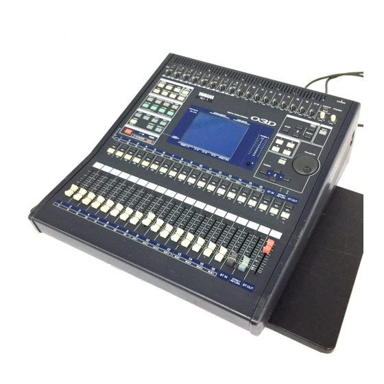
Touring the 03D Touring the 03D In this chapter... Top Panel ............10 Rear Panel . -
Page 20: Top Panel
AUX 3 AUX 4 EFFECT 2 FADER EFFECT 1 FADER STATUS METER MIXING LAYER 1–16 17–24/MASTER The individual sections of the 03D control surface are explained on the following pages. 03D—Owner’s Manual 26dB 26dB 26dB –60 –16 –60 –16 –60 –20 –20... - Page 21 –16 –60 –16 –60 –20 –20 –20 –20 GAIN –34 GAIN –34 GAIN GAIN GAIN GAIN GAIN Top Panel PHONES ST IN MONITOR PHONES SOLO/ 2TR IN –20 –20 –20 –20 –20 GAIN GAIN GAIN GAIN LEVEL LEVEL 03D—Owner’s Manual...
- Page 22 Chapter 2—Touring the 03D Display & Stereo Meters Display The large 320 x 240 dot display with fluorescent backlight provides clear indication of mix settings and operating status. As well as showing parameter values numerically, faders and rotary controls are represented graphically, so you can actually see pan and fader positions.
-
Page 23: Scene Memory
AUX 2 Pre/Post, AUX Pan AUX 3 Pre/Post, AUX Pan AUX 4 Pre/Post, AUX Pan CH 1–16, CH 17–24, YGDAI Out, Pre/Post Eff. Edit, Library, Pre/Post Eff. Edit, Library, Pre/Post SCENE MEMORY UNDO/ REDO STORE RECALL Top Panel 03D—Owner’s Manual... -
Page 24: Midi Remote
Chapter 2—Touring the 03D MIDI Remote The [MIDI REMOTE] button activates the MIDI Remote mode. In this mode, the 03D faders and [ON] buttons of channels 1 to 16 can be used to control other MIDI equip- ment using MIDI commands. The indicator in the button lights up when the MIDI Remote mode is active. - Page 25 Faders The faders are used to adjust input channel and output channel levels. The 03D features 60 mm motorized faders. The function of each fader depends on the selected fader mode and Mixing Layer. See Faders on page 32 for more information. The selected fader mode is shown on the display.
-
Page 26: Rear Panel
Chapter 2—Touring the 03D Rear Panel Rear Panel—Top Half The top half of the rear panel consists of analog inputs and outputs. PHANTOM PHANTOM PHONES 2TR IN (+48V) (+48V) –10dBV ST IN (UNBAL) PHONES This is a stereo (TRS) phone jack. A pair of stereo headphones can be connected here for monitoring. - Page 27 1/4" TRS phone plug Ring (cold) Sleeve (ground) Tip (hot) 1/4" TRS phone plug Ring (cold) Sleeve (ground) Tip (hot) 1/4" TRS phone plug Ring (cold) Sleeve (ground) Tip (hot) 1/4" TRS phone plug Ring (cold) Sleeve (ground) 03D—Owner’s Manual...
- Page 28 Chapter 2—Touring the 03D AUX OUTs These are balanced 1/4-inch phone jacks with a +4 dB nominal output level. Either balanced or unbalanced phone plugs can be connected. They output the aux send sig- nals and can be used to feed external effects processors, foldback amplifiers, and so on.
- Page 29 TO EDITOR POWER MOUSE POWER switch This switch is used to turn on and off the 03D. It’s recessed to prevent accidental oper- ation. TO EDITOR This 9-pin D-sub connector is used to connect the 03D to video-edit controllers. With the current version of the 03D system software, however, this function is not yet avail- able.
- Page 30 These are standard MIDI IN, OUT, and THRU connections. They are used to connect the 03D to other MIDI equipment for control and synchronization. YGDAI slot An optional YGDAI card can be installed here, providing access to the 03D’s eight dig- ital inputs and outputs. See YGDAI Cards on page 223. 03D—Owner’s Manual...
-
Page 31: Block Diagram
Block Diagram Block Diagram 03D—Owner’s Manual... - Page 32 Chapter 2—Touring the 03D 03D—Owner’s Manual...
-
Page 33: Getting Around The User Interface
Title Edit Dialog Box ..........33 03D—Owner’s Manual... -
Page 34: About The User Interface
Chapter 3—Getting Around the User Interface About the User Interface The 03D user interface is both straightforward and easy to use. Apart from the GAIN controls, [PAD] switches, scene memory buttons, and a few other buttons, there are very few dedicated controls. The faders, [ON] buttons, and [SEL] buttons are multi- function controls whose operation depends on the Mixing Layer and fader mode set- tings. - Page 35 CH 7 CH 8 CH 15 CH 16 CH 23 CH 24 BUS 3 BUS 4 — — CH 7 CH 8 CH 15 CH 16 — — CH 23 CH 24 BUS 3 BUS 4 — — 03D—Owner’s Manual...
- Page 36 AUX 1 SEND). The following two tables show what is displayed for the various fader modes and Mixing Layer settings. FADER METER AUX 1 AUX 2 AUX 3 AUX 4 03D—Owner’s Manual Selected page Mixing Layer 1–16 FADER 1–8 9–12 13–16 FADER 1–8 9–12 13–16...
- Page 37 EFFECT RTN 9–12 13–16 ST IN EFFECT RTN 9–12 13–16 ST IN EFFECT RTN 9–12 13–16 ST IN EFFECT RTN 9–12 13–16 ST IN EFFECT RTN 9–12 13–16 ST IN EFFECT RTN 9–12 13–16 ST IN EFFECT RTN 03D—Owner’s Manual...
-
Page 38: Display Elements
Fader knobs appear highlighted when set to the nominal position. Faders can also be adjusted in single-step increments by clicking once with a mouse. Clicking with the left mouse button lowers the fader; clicking with the right button raises it. 03D—Owner’s Manual Nominal... -
Page 39: Cursor Buttons
ON/OFF. It’s also used to confirm settings and enter characters when titling scene memories, effects programs, and so on. On some pages, such as the EQ page, the [ENTER] button is used solely to turn the EQ on and off. Cursor Buttons CURSOR PARAMETER ENTER 03D—Owner’s Manual... -
Page 40: Mouse
Function Menu When a mouse is connected to the 03D, the Function Menu shown below can be used to access MIDI Remote, Setup, Channel Control, and Fader Mode pages. The Function Menu is accessed by clicking the M (Menu) button to the left of the page-title tabs, as shown below. -
Page 41: Mixing Layer
Mixing Layer The 03D [SEL] buttons, [ON] buttons, and faders are multifunction controls. Their exact operation depends on the selected Mixing Layer. Fader operation is also affected by the Fader modes. The operation of all these controls is shown in the following tables. - Page 42 Effect 1 Eff 1 send CH 17–24 Effect 2 Eff 2 send Fader operation is different in MIDI Remote mode. See MIDI Remote on page 243 for more information. 03D—Owner’s Manual Fader 1–8 9–12 13–16 CH 9–12 CH 13–16 fader...
-
Page 43: Title Edit Dialog Box
Use the DEL switch to delete the character at the cursor position and move subsequent characters to the left. When you’ve completed the title, select OK and press the [ENTER] but- ton to continue, or select CANCEL and press the button [ENTER] to cancel the operation. Title Edit Dialog Box 03D—Owner’s Manual... - Page 44 Chapter 3—Getting Around the User Interface 03D—Owner’s Manual...
-
Page 45: Input Channels
This chapter covers input channels 1 to 24 and the stereo input (ST IN). Unless other- wise stated, explanations refer to all of these inputs. The sections of this chapter are arranged in order of signal flow, from input connector through to bus. 03D—Owner’s Manual... -
Page 46: Input Channel Overview
Input Channels 17 to 24 YGDAI SLOT Stereo Input Channel (ST IN) 03D—Owner’s Manual Input channels 1 and 2 feature balanced XLR-3-31-type and balanced phone jack connectors, both with a nominal input range of –60 dB to +10 dB. Individually switchable +48 V phantom powering is supplied to the XLR connector. -
Page 47: Phantom Power (Input Channels 1-8)
INSERT The insert jacks are wired: sleeve–ground, ring–return, tip–send. A wiring diagram for an insert cable is provided on page 17. Phantom Power (input channels 1–8) 03D—Owner’s Manual... -
Page 48: Attenuator
When channels are configured as a stereo pair using the Pair function (Stereo Pairs on page 114), the attenuators for each channel work together, and parameter adjustments can be made with either channel selected. You cannot set different parameters for the odd and even channels. 03D—Owner’s Manual... -
Page 49: Phase
Phase switches can also be selected using the [SEL] but- tons. Normal phase Phase reversed The Phase function is not linked when channels are paired, and can be set indepen- dently for each channel in the stereo pair. Phase 03D—Owner’s Manual... -
Page 50: Channel Delay
Delay = 172 ms, Mix = 50%, Feedback = 18%. When the type is changed from Slap or Echo to Delay, the parameters are set as follows: Delay = 0 ms, Mix = 0%, Feedback = 0%. 03D—Owner’s Manual Type Range Description Delay can be specified in either seconds or sam-... - Page 51 2. Use the [SEL] buttons to select channels and the [ENTER] button to turn the delays on and off. If you are using a mouse, simply click the switches. The switches can also be selected using the cursor buttons. Channel Delay 03D—Owner’s Manual...
-
Page 52: Applying Eq To The Input Channels Eq
Stereo input channel pan can be used to adjust the width of ste- reo signals. Pan, balance, and routing settings are made on the Pan/Route pages. See Stereo Pan, Balance & Routing on page 59 for more information. 03D—Owner’s Manual... -
Page 53: Direct Outputs
EQ, attenuators, dynamics processors, [ON] buttons, solo, channel faders, pre/post settings for the aux sends and effects sends, aux and effects send faders, and routing switches. Pan operation depends on the selected pan mode. See Pan Mode on page 60 for more information. Direct Outputs 03D—Owner’s Manual... -
Page 54: Input Channels Block Diagram
CH INPUT (YGDAI) 17-24 DC CUT GAIN ST IN DC CUT COAXIAL DIGITAL STEREO Emphasis SELECT AES/EBU 03D—Owner’s Manual Meter Meter Meter Meter 4Band DELAY Dynamics Same as 1, 2 Same as 1, 2 Meter Same as 1, 2 Emphasis... - Page 55 About 03D EQ ........
-
Page 56: About 03D Eq
Chapter 5—EQ About 03D EQ 03D EQ is four-band fully parametric, with variable gain, frequency, Q, and ON/OFF parameters. EQ is available on all input channels, the stereo input channel, the stereo output, bus outputs, aux sends, and the onboard effects returns. See the Block Diagram on page 21 for the exact location of each EQ section. -
Page 57: Adjusting The Eq
[HIGH] buttons together. The frequency and Q controls are not reset. Lo-Mid Hi-Mid –18.0 dB to +18.0 dB (0.5 dB steps) 21 Hz–20.1 kHz (1/12 octave steps, 120 steps) 10.0–0.10 (41 steps) Adjusting the EQ High LPF, 10.0–0.10 (41 steps), H.SHELF 03D—Owner’s Manual... -
Page 58: Eq Library
EQ page is already shown, simply click the Library page title tab. The top half of the Library page shows the EQ curve and signal levels for the selected channel. The bottom half contains the EQ library functions. 03D—Owner’s Manual... -
Page 59: Storing Eq Programs
The Title Edit dialog box appears. 5. Enter a title for the EQ program. See Title Edit Dialog Box on page 33 for more information. 6. Press OK on the Title Edit dialog box. The EQ program is stored. Storing EQ Programs 03D—Owner’s Manual... -
Page 60: Recalling Eq Programs
No Data! 4. Use the cursor button to select the RECALL switch, and then press the [ENTER] button. If you are using a mouse, simply click the RECALL switch. The EQ program is recalled. 03D—Owner’s Manual... -
Page 61: Editing Eq Program Titles
4. Edit the program title. See Title Edit Dialog Box on page 33 for more information. 5. When you’ve finished, select OK and press the [ENTER] button. If you are using a mouse, simply click the OK switch. Editing EQ Program Titles 03D—Owner’s Manual... -
Page 62: Preset Eq Programs
Title Bass Drum 1 Bass Drum 2 Snare Drum 1 Snare Drum 2 Tom-tom 1 Cymbal High Hat Percussion E.Bass 1 E.Bass 2 03D—Owner’s Manual Parameter L-MID H-MID PEAKING PEAKING PEAKING +3.5 dB –3.5 dB 0.0 dB 99 Hz 265 Hz 1.05 kHz... - Page 63 Makes a heavily dis- 0.0 dB torted guitar sound 12.6 kHz clearer. — H.SHELF +4.0 dB A variation on program 12.6 kHz — H.SHELF Emphasizes the bright +4.0 dB tones of an acoustic gui- 5.33 kHz tar. — 03D—Owner’s Manual...
- Page 64 A.G.Stroke 2 A.G.Arpeg. 1 A.G.Arpeg. 2 Brass Sec. Male Vocal 1 Male Vocal 2 Female Vo. 1 Female Vo. 2 Chorus&Harmo Total EQ 1 03D—Owner’s Manual Parameter L-MID H-MID L.SHELF PEAKING PEAKING –3.5 dB –2.0 dB 0.0 dB 297 Hz 749 Hz 2.00 kHz...
- Page 65 5.65 kHz recorded in stereo. H.SHELF Use when recording to +3.0 dB or from cassette tape to 12.6 kHz make the sound clearer. — H.SHELF 0.0 dB Use when recording narration. 10.0 kHz — 03D—Owner’s Manual...
- Page 66 Chapter 5—EQ 03D—Owner’s Manual...
-
Page 67: Pan, Routing & Surround Pan
Using Surround Pan ..........65 03D—Owner’s Manual... -
Page 68: Selecting A Pan Mode
Chapter 6—Pan, Routing & Surround Pan Selecting a Pan Mode In addition to stereo pan, the 03D features three surround pan modes. Pan modes are set on the Surround page. 1. Use the [PAN/ROUTING] button to locate the Surround page shown below. -
Page 69: Stereo Pan, Balance & Routing
These pan controls can be used to adjust the width of stereo signals. With the left control set at L16 and the right control set at R16, as shown, the width of a stereo signal is 100%. Stereo Pan, Balance & Routing 03D—Owner’s Manual... - Page 70 (1, 2, 3, 4) and one stereo routing switch (ST). Routing switches are joined into one when bus outs are configured as stereo pairs, as shown here. See Configuring Stereo Pairs on page 114 for more infor- mation. 03D—Owner’s Manual Left Center L16 L15 ··· L2 L1 CENTER R1 R2 ···...
-
Page 71: Stereo Pairs, Pan & Routing
Routing switches are joined into one when bus outs are configured as ste- reo pairs, as shown here. See Configuring Stereo Pairs on page 114 for more information. Stereo Pairs, Pan & Routing 03D—Owner’s Manual... -
Page 72: Surround Pan
Chapter 6—Pan, Routing & Surround Pan Surround Pan As well as normal stereo pan, the 03D features three surround pan modes: 2+2, 3+1, and 3+2+1. In conjunction with the stereo out and bus outs, surround pan controls allow you to pan channel signals in a two-dimensional space. Surround pan controls can be used to move sounds in a circular motion, ellipse, semicircle, or straight line. - Page 73 2+2 Surround Mode The 2+2 surround pan mode uses four channels: front left, front right, rear left, and rear right. The front speakers are fed from the 03D stereo output, while the rear speakers are fed from bus outs 3 and 4.
- Page 74 The front speakers are fed from the 03D stereo output, the rear speakers are fed from bus outs 3 and 4, the front center speaker is fed from bus out 1, and the subwoofer is fed from bus out 2.
-
Page 75: Using Surround Pan
2. Use the [SEL] buttons to select a channel, and then press the [ENTER] but- ton. If you are using a mouse, simply click a pan graph. Using Surround Pan (left/right) parameter indicates the left to right posi- 03D—Owner’s Manual... - Page 76 If you are using a mouse, simply click the EXIT switch. When the Surr. 1–16 or Surr. 17–24 surround pan page appears, you can still use the PARAMETER wheel to pan the sound along the selected trajectory. 03D—Owner’s Manual Trajectories Level meters...
- Page 77 Front left to rear right diagonal —The sound moves on a diagonal trajec- tory from the front left to the rear right. Width, depth and offset can be set for this trajectory. The following illustrations show some typical trajectories. Using Surround Pan 03D—Owner’s Manual...
- Page 78 The shape can be adjusted from a perfect circle to a narrow oval. Use the offset parameters to offset the trajectory to the left, right, front, or rear. The following illustrations show some typical trajecto- ries. 03D—Owner’s Manual...
- Page 79 The front-center sound appears only in the left and right speakers. The front-center sound appears in the center and left and right speakers at the same level. The front-center sound appears only in the center speaker. Using Surround Pan Description 03D—Owner’s Manual...
- Page 80 Chapter 6—Pan, Routing & Surround Pan 03D—Owner’s Manual...
-
Page 81: Solo, Monitors & Meters
Monitor Block Diagram ..........82 03D—Owner’s Manual... -
Page 82: About Monitor & Solo
Chapter 7—Solo, Monitors & Meters About Monitor & Solo The 03D’s flexible monitoring and solo functions are designed for use in a wide range of applications. Pre-fader or post-fader signals from all inputs and outputs can be mon- itored via the monitor out and headphones. Solo in Place and Mixdown Solo mode, which work in conjunction with the stereo output, are also provided. -
Page 83: Monitor Outputs
(TRS) phone jack. The phones signal is the same as the monitor out signal. The PHONES LEVEL control is used to adjust the level of the phones signal. Monitor Outputs MONITOR OUT +4dB (BAL) LEVEL PHONES LEVEL 03D—Owner’s Manual... -
Page 84: Monitoring
It functions independently of the MONO switch on the Solo Setup page. When on, the left and right signals are summed together to form a mono mix. The level of the summed mix is attenuated –3 dB. 03D—Owner’s Manual... -
Page 85: Setting Up Solo
(IN setting), not the cascade slave (OUT setting). LISTEN —These switches set the monitor signal source to pre-fader (PFL) or post-fader (AFL). This is a global setting that affects all input channels, the stereo input channel, Setting Up Solo Description 03D—Owner’s Manual... -
Page 86: Using Solo
[SEL] button lights up. So with the View page selected you can instantly see the settings of the soloed channel without having to select it using the [SEL] button. Channels con- figured as stereo pairs are selected together. 03D—Owner’s Manual Channel On/Off Pair... -
Page 87: Solo Safe
A channel is set as safe when its SOLO SAFE CHANNEL switch is highlighted. Two-track Input The 03D two-track input can be used for confidence monitoring while recording a stereo mix to a master machine. When the MON- ITOR OUT SOLO/2TR IN switch is set to SOLO, solo signals are fed to the monitor out and phones connections. -
Page 88: Solo Block Diagram
Chapter 7—Solo, Monitors & Meters Solo Block Diagram 03D—Owner’s Manual... -
Page 89: Metering
The MODE switches also appear on the CH 17–24 meter page. On the following display page, the meter mode is set to gain reduction and the noise gate patched into channel 5 is shown as being closed. Metering 03D—Owner’s Manual... - Page 90 YGDAI outputs. See Assigning Signals to the YGDAI Outputs on page 224 for more information. When the meter mode is set to GAIN REDUCTION, peak hold for the XGDAI output meters is reset when the CH 1–16 or CH 17–24 meter page is selected. 03D—Owner’s Manual...
-
Page 91: Main Stereo Meters
ST OUT level using the ST OUT fader to prevent signal distortion. –24 –30 –36 –42 The PEAK HOLD ON/OFF switch on the Meter pages also sets the peak hold –48 function for the L STEREO R meters. Metering 03D—Owner’s Manual... -
Page 92: Monitor Block Diagram
Chapter 7—Solo, Monitors & Meters Monitor Block Diagram 1 2 3 4 1 2 3 4 2TR IN 03D—Owner’s Manual SOLO Meter MONI TRIM MONO SOLO/ 2TR IN LEVEL MONITOR LEVEL PHONES... -
Page 93: Stereo Output
Stereo Output Block Diagram ........87 03D—Owner’s Manual... -
Page 94: About The Stereo Output
Routing Signals to the Stereo Output Input channel, stereo input channel, and effects return signals can be routed to the ste- reo output. See Stereo Pan, Balance & Routing on page 59 for more information. 03D—Owner’s Manual ST OUT +4dB(BAL) REC OUT –10dBV... -
Page 95: Setting The Stereo Output Level
The stereo output features stereo four-band parametric EQ. See EQ on page 45 for more information. Stereo Output Dynamics Processor The stereo output features a stereo dynamics processor. See Dynamics Processors on page 143 for more information. Setting the Stereo Output Level 03D—Owner’s Manual... -
Page 96: Stereo Output Delay
2. Use the ST OUT [SEL] button to select the stereo output channels and the [ENTER] button to turn the delays on and off. If you are using a mouse, simply click the switches. The switches can also be selected using the cursor buttons. 03D—Owner’s Manual... -
Page 97: Stereo Output Block Diagram
1 2 3 4 1 2 3 4 Meter 4Band STEREO 4Band Stereo Output Block Diagram Meter Dynamics DELAY BALANCE Dynamics DELAY from BUS OUT 1, 2 COAXIAL DIGITAL DITHER STEREO AES/EBU ST OUT SOURCE REC OUT SELECT 03D—Owner’s Manual... - Page 98 Chapter 8—Stereo Output 03D—Owner’s Manual...
-
Page 99: Aux Sends
Aux Send Block Diagram ......... . . 95 03D—Owner’s Manual... -
Page 100: About Aux Sends
Aux send signals are output via analog phone jacks. They can also be output via the YGDAI digital outputs. The 03D does not have dedicated aux return inputs. Use the input channels or stereo input channel to return aux signals. -
Page 101: Sending Channel Signals To Aux Sends
114), aux send level controls are linked, and adjustments can be made with either channel selected. You cannot set different aux settings for the odd and even channels in a stereo pair. Sending Channel Signals to Aux Sends 03D—Owner’s Manual... -
Page 102: Pre-Fader/Post-Fader Aux Sends
When channels are configured as a stereo pair using the Pair function (Stereo Pairs on page 114), pre/post settings are linked, and adjustments can be made with either chan- nel selected. You cannot set different pre/post settings for the odd and even channels in a stereo pair. 03D—Owner’s Manual... -
Page 103: Setting Aux Send Master Levels
Each aux send features four-band parametric EQ. See EQ on page 45 for more infor- mation. Aux Send Dynamics Processors Each aux send features a dynamics processor. See Dynamics Processors on page 143 for more information. Setting Aux Send Master Levels 03D—Owner’s Manual... -
Page 104: Aux Send Stereo Pairs
If you are using a mouse, position the mouse cursor over a pan control, press and hold the left mouse button, and then drag the mouse. 03D—Owner’s Manual Input channels 1 to 24 use a single pan control to pan signals between the paired aux buses. -
Page 105: Aux Send Block Diagram
R1 R2 ··· R15 R16 Meter Meter Meter Dynamics SOLO Meter Meter Meter Dynamics SOLO Meter Meter Meter Dynamics SOLO Meter Meter Meter Dynamics SOLO Aux Send Block Diagram Right AUX 1 OUT AUX 2 OUT AUX 3 OUT AUX 4 OUT 03D—Owner’s Manual... - Page 106 Chapter 9—Aux Sends 03D—Owner’s Manual...
-
Page 107: Bus Outs
Bus Out Block Diagram ......... . . 102 03D—Owner’s Manual... -
Page 108: About Bus Outs
Chapter 10—Bus Outs About Bus Outs The 03D features four bus outputs. Input channel, stereo input channel, and effects return signals can be routed to the four buses. Each bus out features four-band para- metric EQ and a dynamics processor. Bus outs can be used individually or in stereo pairs. -
Page 109: Setting Bus Out Master Levels
Each bus out features four-band parametric EQ. See EQ on page 45 for more informa- tion. Bus Out Dynamics Processors Each bus out features a dynamics processor. See Dynamics Processors on page 143 for more information. Setting Bus Out Master Levels 03D—Owner’s Manual... -
Page 110: Bus Out Delay
2. Use the [SEL] buttons to select bus outs and the [ENTER] button to turn the delays on and off. If you are using a mouse, simply click the switches. The switches can also be selected using the cursor buttons. 03D—Owner’s Manual... -
Page 111: Routing Bus Signals To The Stereo Bus
Since these parameters are linked, you can adjust the master controls of either bus out in a stereo pair. Routing Bus Signals to the Stereo Bus Center Right CENTER R1 R2 ··· R15 R16 03D—Owner’s Manual... -
Page 112: Bus Out Block Diagram
Bus Out Block Diagram SOLO 1 2 3 4 1 2 3 4 Meter Meter 4Band Meter Meter 4Band Meter Meter 4Band Meter Meter 4Band 03D—Owner’s Manual Meter Meter Meter Dynamics DELAY SOLO Meter Meter Meter Dynamics DELAY SOLO Meter Meter Meter... -
Page 113: Channel Library & View
Channel View ........... 108 03D—Owner’s Manual... -
Page 114: Channel Library
[PAIR] indicated that the aux sends are configured as a stereo pair. The meters next to the CURRENT 03D CONFIGURATION box show the signal level and gain reduction of the selected channel. Paired channels share the same dynamics parameters, so only one gain reduction meter appears. -
Page 115: Storing Channel Programs
The Title Edit dialog box appears. 4. Enter a title for the channel program. See Title Edit Dialog Box on page 33 for more information. 5. Press OK on the Title Edit dialog box. The channel program is stored. Storing Channel Programs 03D—Owner’s Manual... -
Page 116: Recalling Channel Programs
[ENTER] button. If you are using a mouse, simply click the RECALL switch. The channel program is recalled. 03D—Owner’s Manual STORED FROM —This shows which channel’s data is stored in the program. PAN MODE —This shows the pan mode of the channel program. -
Page 117: Editing Channel Program Titles
The Title Edit dialog box appears. 4. Edit the program title. See Title Edit Dialog Box on page 33 for more information. 5. When you’ve finished, press OK on the Title Edit dialog box. Editing Channel Program Titles 03D—Owner’s Manual... -
Page 118: Channel View
If you are using a mouse, simply click the switches and drag the rotary controls and fad- ers. View pages for the different channels are shown below. Input channel view Input channel view with channels configured as a stereo pair 03D—Owner’s Manual... - Page 119 Channel View Input channel view with aux sends 1 and 2 configured as a stereo pair Input channel view with the 2+2 surround pan mode selected Stereo input channel view page Effects return channel view page 03D—Owner’s Manual...
- Page 120 Chapter 11—Channel Library & View Aux send view page Bus out view page Stereo output view page 03D—Owner’s Manual...
-
Page 121: Groups & Pairs
Stereo Pairs ........... . . 114 03D—Owner’s Manual... -
Page 122: Fader Groups
3. Press the [ENTER] button again to enable the fader group. Fader group enabled Fader group disabled 03D—Owner’s Manual ] cursor buttons to select the fader groups and the [SEL] † ] cursor buttons to select the fader group that you want... -
Page 123: Mute Groups
E, F, G, or H. 2. Press the [ENTER] button. If you are using a mouse, simply click the ENABLE switch. 3. Press the [ENTER] button again to enable the mute group. Mute group enabled Mute group disabled Mute Groups 03D—Owner’s Manual... -
Page 124: Stereo Pairs
If you are pairing input channels, the following dialog box appears. 3. Use the cursor buttons to select an option, and then press the [ENTER] button. 03D—Owner’s Manual Make the even numbered channel settings the same as the odd channel settings and activate the channel pair. - Page 125 See Input Channel Stereo Pairs on page 43 for more information. Aux Send Stereo Pairs See Aux Send Stereo Pairs on page 94 for more information. Bus Out Stereo Pairs See Bus Out Stereo Pairs on page 101 for more information. 03D—Owner’s Manual...
- Page 126 Chapter 12—Groups & Pairs 03D—Owner’s Manual...
-
Page 127: Onboard Effects
Effects Block Diagram ..........142 03D—Owner’s Manual... -
Page 128: About The Onboard Effects
Chapter 13—Onboard Effects About the Onboard Effects The 03D features two onboard stereo multi-effects processors: Effect 1 and Effect 2. They provide a wide range of quality effects, including reverb, delay, chorus, flange, amp simulator, and more. There are 34 different effects type available. See Effects Parameters on page 129 for more information. - Page 129 Cross delay at eighth note timing Description Standard chorus effect setting Variation of the chorus effect Somewhat bolder variation of the chorus effect Standard flanging effect setting Variation of the flanging effect Variation of the flanging effect emphasizing the delay 03D—Owner’s Manual...
-
Page 130: Pitch Change
53 Panned Verb Distortion Title 54 Guit. Fixer 55 Drive Guitar 56 Distortion 57 Overdrive 03D—Owner’s Manual Type SYMPHONIC Standard symphonic effect setting PHASER Simulation of a standard phaser Variation of a phaser. This uses all 16 stages of phase... -
Page 131: Dynamic Effects
A type of phaser in which the input controls the phase shift point. Effective when used on percussion instruments Description This can sample 2972.1 ms of data at a sampling rate of 44.1 kHz, 2730.6 ms at 48 kHz, or 4095.9 ms at 32 kHz 03D—Owner’s Manual... -
Page 132: Applying Effects
9. Use the effects library to store the effects settings for future use. See Effects Library on page 125 for more information. 10. Set the EQ, pan, dynamics processors, and so on for the effect return channel. See Effects Returns on page 123 for more information. 03D—Owner’s Manual... -
Page 133: Pre-Fader/Post-Fader Effects Sends
See Metering on page 79 for more information. Send levels can be viewed on the Effects Library page. Applying EQ to Effects Returns Each effects return features four-band parametric EQ. See EQ on page 45 for more information. Pre-fader/Post-fader Effects Sends 03D—Owner’s Manual... -
Page 134: Muting Effects Returns
Aux sends The effects return signals can be sent to aux sends 1 to 4. Effects return signals cannot sent to the Effects buses, as this would create a loop. See Aux Sends on page 89 for more information. 03D—Owner’s Manual... -
Page 135: Effects Library
Effect 2. If you are using a mouse and the Eff. Edit page is already shown, simply click the Library page title tab. The top half of the Library page shows the type of effect currently selected and level meters for the effects send. The bottom half contains the effects library functions. 03D—Owner’s Manual... -
Page 136: Storing Effects Programs
The Title Edit dialog box appears. 4. Enter a title for the effects program. See Title Edit Dialog Box on page 33 for more information. 5. Press OK on the Title Edit dialog box. The effects program is stored. 03D—Owner’s Manual... -
Page 137: Recalling Effects Programs
No Data! 3. Use the cursor button to select the RECALL switch, and then press the [ENTER] button. If you are using a mouse, simply click the RECALL switch. The effects program is recalled. Recalling Effects Programs 03D—Owner’s Manual... -
Page 138: Editing Effects Program Titles
If you are using a mouse, simply click the TITLE EDIT switch. The Title Edit dialog box appears. 4. Edit the program title. See Title Edit Dialog Box on page 33 for more information. 5. When you’ve finished, press OK on the Title Edit dialog box. 03D—Owner’s Manual... -
Page 139: Effects Parameters
Density of the reflections. Number of early reflections. High frequency amount of the feedback, expressed as a ratio relative to the FB.GAIN. Amount of feedback. Cutoff frequency of the high pass filter. Cutoff frequency of the low pass filter. 03D—Owner’s Manual... - Page 140 SINE, TRI HSF F 500 Hz–16 kHz HSF G –12 to +12 dB 03D—Owner’s Manual Range Delay time of the L channel. Delay time of the center delay. Delay time of the R channel. Level of the L channel delay sound.
- Page 141 –12 to +12 dB Gain of the low shelving filter. HSF F 500 Hz to 16 kHz Frequency of the high shelving filter. HSF G –12 to +12 dB Gain of the high shelving filter. Effects Parameters Description Description Description 03D—Owner’s Manual...
- Page 142 –50 to +50 cent DELAY 0.1–1000.0 ms FB.GAIN –99 to +99% MODE 1–10 03D—Owner’s Manual Range Modulation speed. Modulation depth. Select the direction in which the sound will move. Frequency of the low shelving filter. Gain of the low shelving filter.
- Page 143 PM DEPTH 0–100% Pitch modulation depth. AM DEPTH 0–100% Volume modulation depth. Delay time from the direct sound until the modulated MOD.DLY 0.0–500.0 ms sound. WAVE SINE, TRI Modulation waveform. SINE: sine wave, TRI: triangle wave Effects Parameters Description Description 03D—Owner’s Manual...
- Page 144 FB.GAIN –99 to +99% MOD.DLY 0.0–500.0 ms WAVE SINE, TRI 03D—Owner’s Manual Range Length of reverb. Delay time until the early reflections of the reverb are heard. Length of the high frequency portion of the reverb, expressed as a ratio relative to REV.TIME.
- Page 145 FREQ. 0.05–40.00 Hz Modulation speed. DEPTH 0–100% Modulation depth. Delay time from the direct sound until the modulated MOD.DLY 0.0–500.0 ms sound. WAVE SINE, TRI Modulation waveform. SINE: sine wave, TRI: triangle wave Effects Parameters Description Description 03D—Owner’s Manual...
- Page 146 DEPTH 0–100% DIR. WAVE SINE, TRI 1. L<->R, L-->R, L<--R, Turn L, Turn R 03D—Owner’s Manual Range Length of reverb. Delay time until the early reflections of the reverb are heard. Length of the high frequency portion of the reverb, expressed as a ratio relative to REV.TIME.
- Page 147 0–100% Density of the reflections. ER NUM. 1–16 Number of reflections. Balance between the delay and the early reflections delay. 0 ER BAL. 0–100% is only delay. 1. S-Hall, L-Hall, Random, Reverse, Plate, Spring Effects Parameters Description Description 03D—Owner’s Manual...
- Page 148 DENSITY 0–100% THRU,21 Hz–8.0 50 Hz–16.0 kHz, THRU REV.BAL 0–100% 03D—Owner’s Manual Range Delay time of the L channel. Delay time of the R channel. Feedback delay time. Feedback amount. High frequency portion of the feedback, expressed as a ratio relative to FB.GAIN.
- Page 149 –12 to +12 dB Gain of the parametric equalizer. EQ Q 10.0–0.40 Bandwidth of the parametric equalizer. 1. STK-M1, STK-M2, THRASH, MIDBOOST, CMB-PG, CMB-VR, CMB-DX, CMB-TWN, MINIAMP, FLAT 2. DST1, DST2, OVD1, OVD2, CRN Effects Parameters Description Description 03D—Owner’s Manual...
- Page 150 –12 to +12 dB DECAY 1. 0.02 ms–2.13 s fs=32 kHz/44.1 kHz, 0.02 ms–1.96 s fs=48 kHz 2. 6 ms–46.0 s fs=32 kHz/44.1 kHz, 5 ms–42.3 s fs=48 kHz 03D—Owner’s Manual Range Input sensitivity. Select the filter type. Filter frequency offset.
- Page 151 If the REC MODE is set to MANUAL, press the [ENTER] button to start recording. If REC MODE is set to INP TRG, recording starts automatically when the input signal exceeds the TRG LEVEL. Effects Parameters Description Description 03D—Owner’s Manual...
-
Page 152: Effects Block Diagram
If the PLY MODe is set to INP TRG, playback starts automatically when the input signal exceeds the TRG LEVEL. Effects Block Diagram Meter INTERNAL EFFECT 1 Meter INTERNAL EFFECT 2 03D—Owner’s Manual Meter Meter Meter EFF RTN Fader 4Band Dynamics BALANCE... -
Page 153: Dynamics Processors
Preset Dynamics Programs ........157 03D—Owner’s Manual... -
Page 154: About The Dynamics Processors
Expand Ducking Compander(H) Compander(S) A.Dr.BD A.Dr.BD A.Dr.BD A.Dr.SN A.Dr.SN A.Dr.SN A.Dr.SN A.Dr.Tom A.Dr.OverTop E.B.Finger E.B.Slap Syn.Bass Piano1 Piano2 03D—Owner’s Manual Type COMP E.Guitar GATE A.Guitar EXPANDER Strings1 DUCKING Strings2 COMPANDER (H) Strings3 COMPANDER (S) BrassSection COMP Syn.Pad GATE SamplingPerc COMPANDER (H) - Page 155 So the gain reduction meter displays the amount of gain reduction when the input signal is below the thresh- old, and when there is no input signal. About the Dynamics Processors Description 03D—Owner’s Manual...
-
Page 156: Patching In A Dynamics Processor
6. Use the cursor button to select the dynamics processor parameters and the PARAMETER wheel or mouse to adjust them. While the cursor is in the PARAMETER window, the [ENTER] button functions as dynamics processor on/off switch, allowing for quick A/B comparisons. 03D—Owner’s Manual... -
Page 157: Dynamics Library
Edit page is already shown, simply click the Library page title tab. The top half of the Library page shows the dynamics TYPE/CURVE and gain reduction and level meters for the selected channel. The bottom half contains the dynamics library functions. 03D—Owner’s Manual... -
Page 158: Storing A Dynamics Program
The Title Edit dialog box appears. 5. Enter a title for the dynamics program. See Title Edit Dialog Box on page 33 for more information. 6. Press OK on the Title Edit dialog box. The dynamics program is stored. 03D—Owner’s Manual... -
Page 159: Recalling A Dynamics Program
Dynamics programs that do not contain data have the title No Data! 4. Use the cursor button to select the RECALL switch, and then press the [ENTER] button. If you are using a mouse, simply click the RECALL switch. The Dynamics program is recalled. Recalling a Dynamics Program 03D—Owner’s Manual... -
Page 160: Editing Dynamics Program Titles
If you are using a mouse, simply click the TITLE EDIT switch. The Title Edit dialog box appears. 4. Edit the program title. See Title Edit Dialog Box on page 33 for more information. 5. When you’ve finished, press OK on the Title Edit dialog box. 03D—Owner’s Manual... -
Page 161: Processor Types
–70 –60 –50 –40 –30 –20 –10 Input Level (dB) Compression ratio = 20:1 –10 Threshold = –20dB –20 Knee = hard –30 –40 –50 –60 –70 –70 –60 –50 –40 –30 –20 –10 Input Level (dB) Range 03D—Owner’s Manual... - Page 162 Parameter THRESHOLD RANGE ATTACK HOLD DECAY 03D—Owner’s Manual Range –54 dB to 0 dB (55 steps) –70 dB to 0 dB (71 steps) 0–120 ms (1 ms steps) 0.02 ms–1.96 s (sampling rate @ 48 kHz) 0.02 ms–2.13 s (sampling rate @ 44.1 kHz) 0.03 ms–2.94 s (sampling rate @ 32 kHz)
- Page 163 Processor Types –10 Threshold = –20dB –20 –30 –40 –50 Range = –30dB –60 –70 –70 –60 –50 –40 –30 –20 –10 Input Level (dB) Range 03D—Owner’s Manual...
- Page 164 Signals above the threshold pass through the expander unaffected. Signals at and below the threshold level are attenuated by the amount specified using the Ratio parameter. The trigger signal is sourced using the KEY IN parameter. 03D—Owner’s Manual Expansion ratio = 2:1 Knee = hard Threshold = –10dB...
- Page 165 1:1, 1.1:1, 1.3:1, 1.5:1, 1.7:1, 2:1, 2.5:1, 3:1, 3.5:1, 4:1, 5:1, 6:1, 8:1, RATIO 10:1, 20:1 (15 steps) WIDTH 1 dB–90 dB (1 dB steps) Processor Types Width –10 –20 Threshold –30 –40 –50 –60 –70 –70 –60 –50 –40 –30 Input Level (dB) Soft Compander Range Threshold –20 –10 03D—Owner’s Manual...
- Page 166 0.1–0.5s are a good place to start. OUT GAIN —This sets the compander’s output signal level. It can be used to compen- sate for the overall level change caused by the compression and expansion processes. 03D—Owner’s Manual Range 0–120 ms (1 ms steps) 5 ms–42.3 s (sampling rate @ 48 kHz)
-
Page 167: Preset Dynamics Programs
Compressor program for use Attack (ms) with acoustic kit’s bass drum. Outgain (dB) Knee Release (ms) Threshold (dB) –11 Range (dB) –53 Gate program for use with acous- Attack (ms) tic kit’s bass drum. Hold (ms) 1.93 Decay (ms) Description 03D—Owner’s Manual... - Page 168 Compressor A.Dr.SN Expander A.Dr.SN Gate A.Dr.SN Compander (S) A.Dr.Tom Expander A.Dr.OverTop Compander (S) E.B.Finger Compressor 03D—Owner’s Manual Type Parameter Value Threshold (dB) Ratio ( :1) Attack (ms) Outgain (dB) Width (dB) Release (ms) Threshold (dB) Ratio ( :1) Attack (ms)
- Page 169 Ratio ( :1) Attack (ms) Compressor program for strings. Outgain (dB) Knee Release (ms) Threshold (dB) –12 Ratio ( :1) Attack (ms) A variation on program 23, intended for violas or cellos. Outgain (dB) Knee Release (ms) 1.35 S Description 03D—Owner’s Manual...
- Page 170 Syn.Pad Compressor SamplingPerc Compander (S) Sampling BD Compressor Sampling SN Compressor Hip Comp Compander (S) Solo Vocal1 Compressor 03D—Owner’s Manual Type Parameter Value Threshold (dB) Ratio ( :1) Attack (ms) Outgain (dB) Knee Release (ms) Threshold (dB) Ratio ( :1)
- Page 171 Outgain (dB) down. It can also be used with Knee hard the stereo input. Release (ms) Threshold (dB) –16 Ratio ( :1) Attack (ms) A variation of program 39 with greater compression. Outgain (dB) Knee Release (ms) Description 03D—Owner’s Manual...
- Page 172 Chapter 14—Dynamics Processors 03D—Owner’s Manual...
-
Page 173: Scene Memories
Recalling Scene Data Safely ........174 03D—Owner’s Manual... -
Page 174: About Scene Memories
Scene memories are memory locations that are used to store mix scenes. A mix scene consists of all 03D mix settings (i.e., EQ, fader positions, and so on). There are 50 scene memories, and they can be titled for easy identification. Scene memories can be stored and recalled in three ways: •... -
Page 175: Scene Memory 00
Scene memory 00 is a little different to scene memories 1 through 50. It’s a read-only memory and contains the initial 03D settings. You can recall it, but you cannot store it. When you want to reset all mix settings to their initial values, recall scene memory 00. -
Page 176: Storing Mix Scenes
2. Use the cursor buttons to select the scroll box listing the scene memories. 3. Use the PARAMETER wheel to scroll through the scene memory list. If you are using a mouse, position the mouse cursor over the parameter box, 03D—Owner’s Manual ] and [ ] buttons to select the scene memory π... - Page 177 See Title Edit Dialog Box on page 33 for more information. 6. Press OK on the Title Edit dialog box. The mix scene is stored to the selected scene memory, the scene memory number stops flashing, and the EDIT indicator disappears. Storing Mix Scenes 03D—Owner’s Manual...
-
Page 178: Recalling Mix Scenes
Nobody likes sudden surprises or speaker damage. To prevent mix scenes being recalled accidentally, a preference can be set so that the 03D displays a confirmation dialog box during the recall process. See RECALL CONFIR- MATION on page 213 for more information. -
Page 179: Undoing Mix Scene Recalls
For example, most MIDI keyboards transmit a Program Change message when a voice is selected. This could be used to recall the corresponding mix scene on the 03D. So with just one button press, your synthesizer, 03D, and other MIDI equipment is reconfig- ured ready for the next song or scene. -
Page 180: Write Protecting Scene Memories
If you are using a mouse, simply click the corresponding ON switch. To turn off the write protection, select the corresponding OFF switch and press the [ENTER] button. If you are using a mouse, simply click the OFF switch. 03D—Owner’s Manual ] buttons, or mouse. -
Page 181: Editing Scene Memory Titles
The Title Edit dialog box appears. 4. Edit the scene memory title. See Title Edit Dialog Box on page 33 for more information. 5. When you’ve finished, press OK on the Title Edit dialog box. Editing Scene Memory Titles 03D—Owner’s Manual... -
Page 182: Sorting Scene Memories
4. Use the PARAMETER wheel or mouse to select the insertion point. 5. Use the cursor buttons to select the EXECUTE switch. 6. Press the [ENTER] button. If you are using a mouse, simply click the EXECUTE switch. The source scene memory is renumbered. 03D—Owner’s Manual... -
Page 183: Setting A Fade Time
5. Store the current mix settings to a scene memory. The fade time parameters are stored along with other mix settings. When this scene memory is recalled, enabled faders move to their new positions at the specified fade time. Setting a Fade Time 03D—Owner’s Manual... -
Page 184: Recalling Scene Data Safely
When a mix scene is recalled, providing that the master ENABLE switch is on, mix set- tings are not applied to safe channels. The Recall Safe settings are stored as part of the 03D Setup data. They are not stored in scene memories. -
Page 185: Automix
Clearing Automix Memories ........206 03D—Owner’s Manual... -
Page 186: About Automix
Chapter 16—Automix About Automix The 03D’s Automix function provides dynamic mix automation referenced to an exter- nal timecode source. The external timecode can be either MTC or MIDI Clock. The automix start time can be offset relative to the external timecode. Automix can be used to record and playback fader moves, channel mutes, EQ changes, pan, and more. -
Page 187: Automix Memory
When an automix is recalled, the contents of the selected automix become the current automix. The current automix is remembered when the 03D is turned off. So they don’t have to store the current automix before the 03D is turned off. - Page 188 AUTO REC switch. In this mode, automix recording can be performed repeatedly. Recording starts as soon as the 03D receives timecode or a MIDI Start or Continue message. You cannot start recording events until you select a channel for automix recording, however, using the [SEL] buttons.
- Page 189 22:30. That could be interpreted as either 22:30 before the automix start or 22:30 after the start. The 03D uses the following method to determine the correct point: If the received timecode value is within one hour of the automix start (00:00:00.00 or offset value), it is interpreted as being before the automix start, and the first mix scene is...
-
Page 190: Creating A New Automix
2. Press the [ENTER] button to toggle automix on and off. If you are using a mouse, simply click the AUTOMIX ENABLE switch. When automix is enabled, automix starts automatically when MIDI Start or Continue messages or MTC are received. 03D—Owner’s Manual Automix OFF. Automix ON... -
Page 191: Setting The Time Base
MIDI IN or TO HOST connection. See MIDI Connec- tors & TO HOST on page 232 for more information. The 03D’s time base settings must be set to match the incoming timecode signal. Time base settings are made in the TIME BASE section of the Main automix page. -
Page 192: Setting An Automix Offset
TC Counter MEAS/BEAT/CLK Counter 03D—Owner’s Manual When MTC is used as the time base, the offset is specified in hours, minutes, seconds, and frames. When an offset is set, events in the current automix are moved by the specified amount. -
Page 193: Safe Channels
To protect a channel completely, use the RECALL SAFE CHANNEL function on the scene memory RCL. Safe page. See Recalling Scene Data Safely on page 174 for more information. Note: During automix recording these settings are ignored, and existing automix data plays as normal. Safe Channels 03D—Owner’s Manual... -
Page 194: Selecting Parameters For Recording
Input attenuator and aux pair pan settings can also be stored in a channel program, which can be recalled by the automix. 03D—Owner’s Manual Parameters Normal CH faders, CH AUX sends, & CH Effect sends... -
Page 195: Recording An Automix
[ENTER] button. If you are using a mouse, simply click the REC switch. The 03D engages Rec Ready mode and the REC switch flashes. The [SEL] button indicator of the selected channel goes off. The [SEL] buttons now function as channel record select buttons. - Page 196 With the first part of the automix completed, you can do one of the following: • Play back the automix—Playing Back an Automix on page 187 • Record parameter changes for other channels—go back to step 6 of this procedure 03D—Owner’s Manual...
-
Page 197: Playing Back An Automix
• Extract events—Extracting Events on page 198 Playing Back an Automix If the Automix function is enabled, playback starts automatically when the 03D receives timecode or a MIDI Start or Continue message. This is Auto Play mode. Auto Play can, however, be cancelled by pressing the STOP switch. -
Page 198: Rerecording Events
[ENTER] button. If you are using a mouse, simply click the REC switch. The 03D engages Rec Ready mode and the REC switch flashes. 4. Use the [SEL] and [MIXING LAYER] buttons to select the channel your want to rerecord. See Mixing Layer on page 31 for more information. -
Page 199: Automix Punch-In/Punch-Out
Punch-in recording can be started during playback by pressing the REC switch. Like- wise, punch-in recording can be started while the 03D is in Rec Ready mode by pressing the PLAY switch. In both cases, however, you must use the [SEL] buttons to select chan- nels for automix recording. -
Page 200: Editing Fader Moves On-The-Fly
[ENTER] button. If you are using a mouse, simply click the REC switch. The 03D engages Rec Ready mode and the REC switch flashes. 6. Start the external timecode source. Automix recording starts and the REC switch stops flashing and appears highlighted. - Page 201 Channel fader 4, on the other hand, has been raised, and the arrow pointing down indicates that the fader needs to be moved down to get back to the fader position previously recorded. Editing Fader Moves On-the-fly 03D—Owner’s Manual...
- Page 202 The TIME parameter determines how long it takes the level to return to the previous value, and affects only the normal channel faders. 03D—Owner’s Manual Time Time...
-
Page 203: Editing Events Off-Line
PARAMETER wheel to scroll through the events. If you are using a mouse, position the mouse cursor over the scroll arrows, press and hold the left mouse button, and then drag the mouse. Editing Events Off-line Parameters 03D—Owner’s Manual... - Page 204 INS. DEL. COPY PASTE 03D—Owner’s Manual Switch Inserts a new event. The new event is assigned the same time value as the preceding event. The time value, event type, and the chan- nel can then be set as required.
- Page 205 Time signature set to 3/4 (normally in list). Measure can also be set Time signature change events with no value specified look like this Ch 1 Channel 1 fader level set to 0dB Bus2 Bus 2 ON/OFF set to OFF Editing Events Off-line Description Description 03D—Owner’s Manual...
- Page 206 63 Hz 66 Hz 70 Hz 74 Hz 79 Hz 83 Hz 88 Hz 94 Hz 99 Hz 105 Hz 111 Hz 03D—Owner’s Manual Frequency Value Frequency 118 Hz 667 Hz 125 Hz 707 Hz 132 Hz 749 Hz 140 Hz...
- Page 207 +14.5 dB +15.0 dB +15.5 dB +16.0 dB +16.5 dB +17.0 dB +17.5 dB +18.0 dB Value 0.63 0.16 0.55 0.14 0.50 0.12 0.45 0.11 0.40 0.10 0.35 Low Shelving 0.32 High Shelving 0.28 0.25 0.22 0.20 0.18 03D—Owner’s Manual...
-
Page 208: Extracting Events
4. Use the cursor buttons to select an EVENT SELECT switch, and then press the [ENTER] button to activate it. If you are using a mouse, simply click an EVENT SELECT switch. 03D—Owner’s Manual... - Page 209 Events can be moved only when the Undo function is enabled and there is sufficient memory. When events are moved, events of the same type at the specified destination Extracting Events The EVENT SELECT switches are used to select the type of event to be extracted, moved, or trimmed. Parameters Function 03D—Owner’s Manual...
-
Page 210: Undoing Automix Operations
• A new automix is created (see Creating a New Automix on page 180) • An automix is recalled (see Recalling Automixes on page 203) 03D—Owner’s Manual The undo controls shown here are available on the Main and Mem- ory pages. Operation is identical on both pages. The main undo... -
Page 211: Clearing The Undo Buffer
3. Use the cursor buttons to select OK, and then press the [ENTER] button. If you are using a mouse, simply click OK. The contents of the undo buffer are cleared, and the UNDO BUF. SIZE window indi- cates 0K. Clearing the Undo Buffer 03D—Owner’s Manual... -
Page 212: Storing Automixes
4. Enter a title for the automix. See Title Edit Dialog Box on page 33 for more information. 5. Press OK on the Title Edit dialog box. The contents of the current automix are stored to the selected automix memory. 03D—Owner’s Manual... -
Page 213: Recalling Automixes
If there’s not enough memory available to recall an automix and have the current automix copied to the undo buffer, the current automix and automix memory can simply be swapped. See Swapping the Current Automix on page 204 for more information. Recalling Automixes 03D—Owner’s Manual... -
Page 214: Swapping The Current Automix
A confirmation dialog box appears. 5. Use the cursor buttons to select OK, and then press the [ENTER] button. If you are using a mouse, simply click OK. The current automix and automix memory are swapped without affecting the undo buffer. 03D—Owner’s Manual... -
Page 215: Editing Automix Titles
If you are using a mouse, simply click the TITLE EDIT switch. The Title Edit dialog box appears. 4. Edit the automix title. See Title Edit Dialog Box on page 33 for more information. 5. When you’ve finished, press OK on the Title Edit dialog box. Editing Automix Titles 03D—Owner’s Manual... -
Page 216: Clearing Automix Memories
If you are using a mouse, simply click the CLEAR switch. A confirmation dialog box appears. 5. Press OK to confirm. The selected automix memory is cleared, and the title, size, time base, and start values are reset. 03D—Owner’s Manual... -
Page 217: Other Functions
Initializing the 03D ........ -
Page 218: User Define Buttons
If you are using a mouse, simply click an APPLY switch. The following functions can be assigned to the USER DEFINE buttons. 03D—Owner’s Manual The functions of the USER DEFINE buttons are continuously shown by the four switches at the top-right of the display, as shown here. - Page 219 first in the series, nothing is recalled when a current–1 function is used. If the specified mix scene or effects program contains no data, the next scene or pro- gram that contains data is recalled. User Define Buttons Description Description Description 03D—Owner’s Manual...
- Page 220 When a pair of USER DEFINE buttons are set to PAN LEFT and PAN RIGHT, or PAN FRONT and PAN REAR, the indicators make it easy to check the pan position of the 03D—Owner’s Manual Same as REC switch on Main automix page...
- Page 221 USER DEFINE buttons [1] and [2]. PAN LEFT PAN RIGHT PAN LEFT PAN RIGHT PAN LEFT PAN RIGHT User Define Buttons Pan set at center Pan set between L16 and center Pan set between R16 and center 03D—Owner’s Manual...
-
Page 222: Using The Onboard Oscillator
Chapter 17—Other Functions Using the Onboard Oscillator The 03D features a useful, onboard audio oscillator, which can be assigned to the bus outputs, aux sends, stereo output, and onboard effects. It can be used for calibration or diagnostic purposes. Assigning a burst noise waveform to the onboard effects proces- sors, for example, is a convenient way to audition reverb settings. -
Page 223: 03D Preferences
RECALL CONFIRMATION When this preference is set to ON, the 03D display a confirmation dialog box whenever a mix scene or library program is recalled. This is useful for preventing mix scenes and library programs from being recalled accidentally. -
Page 224: Checking The Battery
3. Release the [STORE] button and select an option. Calibrating the Faders If the 03D is not used for a long time, is moved to a new location, or fader movements have been obstructed, the faders may need calibrating. The calibration process calcu- lates the torque required by each fader motor to drive its fader accurately and smoothly. -
Page 225: Digital I/O
Cascading the 03D ........ -
Page 226: Wordclock Setup
44.1 kHz and 48 kHz are available. When the internal wordclock generator is used, the 03D can be used as wordclock master, with other digital devices working as wordclock slaves. Alternatively, the 03D can be used with external wordclock rates of between 32 kHz –6% and 48 kHz +6%. - Page 227 03D Preferences on page 213 for more information. No wordclock signal available. FS —When the 03D is locked to a wordclock, the sampling rate appears here (48k, 44.1k, or 32k). When it is unlocked, the display shows UNLOCK. If another page is accessed in the unlocked state, UNLOCK appears on that page too.
- Page 228 For correct operation it is essential that wordclock cabling be terminated correctly. The 03D has a wordclock termination ON/OFF (75 ) switch on the rear panel. Wordclock is a TTL signal, and IN and OUT connections use BNC connectors. Three wordclock distribution examples are shown below.
-
Page 229: Digital Stereo Out
Digital Stereo Out The 03D features both AES/EBU and COAX- IAL-type digital stereo outputs. They output the same digital audio signal but in different formats. The XLR-3-32-type connector outputs AES/EBU format digital audio, while the COAXIAL connec- tor outputs Consumer format digital audio. -
Page 230: Output Dither
DIGITAL STEREO OUT or YGDAI card. If, for example, you have a 20-bit digital recorder connected to the 03D’s DIGITAL STE- REO OUT for use as a master recorder, set the wordlength to 20 and turn on dither for the ST OUT DIGITAL. -
Page 231: Digital Stereo In
Emphasis When a digital audio signal containing emphasis is connected to the digital stereo input, the 03D automatically detects it and de-emphasizes as necessary. Once a signal has been de-emphasized, it’s processed and output by the 03D without emphasis. The 03D cannot apply emphasis to digital output signals. -
Page 232: Digital Input Monitor
Experimental Unknown COPY —This field shows the copy status of a digital input signal. Only COAXIAL sig- nals contain copy information. Prohibit 03D—Owner’s Manual 32 kHz sampling rate 44.1 kHz sampling rate 48 kHz sampling rate Sampling rate unknown No signal connected or signal invalid... -
Page 233: Ygdai Cards
I/O support for several industry standard digital audio formats and protocols. Using a YGDAI card, the 03D’s bus, aux, and input channel sig- nals 1–16 can be output to other digital audio equipment, including digital multitrack recorders. - Page 234 DA-88. The digital outputs can be any combination of bus outs, aux sends, and direct outputs from the first 16 input channels. So even though the 03D has only four bus out- puts, up to eight tracks can be recorded simultaneously. When the 03D is used with a digital multitrack recorder, input channels 17 to 24 function as tape returns.
- Page 235 YGDAI Cards YGDAI Block Diagram 03D—Owner’s Manual...
- Page 236 Chapter 18—Digital I/O Installing YGDAI Cards Warning: Turn off the 03D before installing a YGDAI card. Failure to do so is an electrical shock hazard, and may damage the 03D or card. 1. Turn off the 03D. 2. Undo the four fixing screws and remove the slot cover, as shown below.
-
Page 237: Cascading The 03D
The 03D can also be cascaded with the Yamaha 02R Digital Recording Console, which is an 8-bus console. The CD8-CS Cascade Kit con- tains two cards and one cable. This is all that is required to cascade two 03Ds or a 03D and 02R together. - Page 238 1 routes to 03D bus 1, cascade bus 2 routes to 03D bus 2, and so on. The 03D does not use buses 5 to 8, so there is no reason to select those buses.
- Page 239 Solo signals are output through the monitor section of the cascade master. 4. Press the [SOLO] button on the cascade master to cancel solo. Cascade Block Diagram SELECT ON/OFF INPUT (CD8-CS) SOLO 1 2 3 4 Cascading the 03D OUTPUT (CD8-CS) 03D—Owner’s Manual...
- Page 240 Chapter 18—Digital I/O 03D—Owner’s Manual...
-
Page 241: Midi
MIDI and the 03D ........ -
Page 242: Midi And The 03D
In MULTIPORT mode, TO HOST operation is virtually the same as in STANDARD I/F mode except for the addition of MIDI Port Select messages. In this way the 03D func- tions like it has multiple MIDI ports, although physically it does not have multiple ports. -
Page 243: Midi & To Host Data Receive Indicators
MMC, Fader Start, and the four MIDI Remote pages. Port 2 data is echoed through to the MIDI OUT for connection to other MIDI gear. The 03D Multiport mode does not support fast MIDI, which is used by some multiport devices and software. - Page 244 MIDI OUT connector according to the ECHO parameters on the MIDI Setup page. See MIDI Setup on page 235 for more information. While MIDI messages received at the 03D’s MIDI IN pass through the 03D to the controlling computer via the TO HOST connection.
-
Page 245: Midi Setup
These setting are really intended for those who write their own computer programs to control the 03D. You should not change them unless you know what you are doing. If you are using a standard MIDI sequencer program, use the following settings. - Page 246 CH) are echoed to the MIDI OUT. PARAMETER CHANGE —Parameter Change System Exclusive messages are used to control 03D parameters in real time. The three switches in this group are as follows. Tx determines whether or not the 03D transmits Parameter Change System Exclusive mes- sages.
- Page 247 Basically, the Device No. determines the MIDI Channel used for System Exclusive data transfer. If you are using only one 03D, the Device No. can be set at 1. If you are using more than one 03D, however, set each 03D to a different Device No.
-
Page 248: Midi Monitor
**H) can be filtered from the MIDI IN and TO HOST windows independently. 2. Use the cursor buttons to select the filter switches in the Filtering win- dows and the [ENTER] button to turn them on and off. If you are using a mouse, simply click the filter switches. 03D—Owner’s Manual... -
Page 249: Program Change Assign
Program Change Assign The PGM Asgn. page is used to assign 03D scene memories to MIDI Program Changes. Program Change messages can be used to recall 03D mix scenes. See Using MIDI Pro- gram Change Messages on page 169 for more information. Scene memories can be assigned to Program Change messages from 1 to 128. -
Page 250: Control Change Assign
The CTL Asgn. page is used to assign 03D parameters to MIDI Control Changes. Con- trol Changes can be used to control 03D mix settings in real time. When an 03D mix parameter is adjusted, a Control Change messages is transmitted. This message could be recorded to a MIDI sequencer or controlling computer. -
Page 251: System Exclusive Parameter Control
Q parameter over its normal range from 10.0 to 0.01. System Exclusive Parameter Control Parameters that cannot be assigned to Control Changes can be controlled in real time by transmitting and receiving System Exclusive messages. See MIDI Data Format on page 271 for more information. 03D—Owner’s Manual... -
Page 252: Bulk Dump
Chapter 19—MIDI Bulk Dump From the Bulk page, 03D data can be dumped to and from other MIDI devices, such as a MIDI data filer, controlling computer, or another 03D. This can be used to backup 03D data, or transfer data between 03Ds. -
Page 253: Midi Remote
• User defined (user defined MIDI commands) Up to four display pages can be configured for use with the above. Connecting for Remote Control The following illustration is an example of how equipment can be connected to the 03D for remote control operation. MIDI OUT... - Page 254 CH parameters, press and hold the left mouse button, and then drag the mouse. The CH/PORT parameters determine which ports the 03D uses to transmit and receive MIDI Remote messages for the four MIDI Remote pages: MIDI OUT or TO HOST.
- Page 255 1. Use the [MIDI REMOTE] button to locate the P.Mix01, 02R, or 03D page. 03D channel faders 1 to 16 correspond to faders 1 to 16 on the remote mixer. Adjusting an 03D fader changes the corresponding fader on the remote mixer.
- Page 256 Select the RCL switch, and then press the [ENTER] button to recall the reverb program on the ProR3 or REV500. The reverb program is recalled and the 03D’s faders and dis- play controls are updated to reflect the new parameter positions.
- Page 257 1 to 8 or channels 9 to 16. Use the CH switches to select these channel groups. When an 03D fader in group 1 to 8 or group 9 to 16 is operated, the corre- sponding group is selected on the display.
- Page 258 16, 17 to 24, and 25 to 32 in four groups. Use the PART switches to select these groups. When group 1 to 8 or 9 to 16 is selected, 03D faders correspond to parts 1 to 16, and when an 03D fader in group 1 to 8 or group 9 to 16 is operated, the corresponding group is selected on the display.
- Page 259 2. In Pro Tools, choose Peripherals from the Setups menu. 3. Turn on DEVICE CS-10. 03D channel faders 1 to 8 correspond to tracks 1 to 8 on Pro Tools. Adjusting an 03D fader changes the corresponding level in Pro Tools.
- Page 260 1. Use the [MIDI REMOTE] button to locate the User Def. page. On the User Define page, you define the MIDI commands to be sent when the 03D’s faders or [ON] buttons are operated. Two commands can be defined for the [ON] but- tons.
-
Page 261: Troubleshooting
Make sure that the power cord is connected to a suitable AC wall out- let. Make sure that the 03D POWER switch is set to the ON position. If you still cannot turn on the 03D, contact your Yamaha dealer. - Page 262 Are those channels set as safe channels? See Recalling Scene Data Safely on page 174 for more information. Make sure that the 03D is configured to receive Program Change mes- sages and the MIDI Channels match. See MIDI Setup on page 235 for more information.
-
Page 263: Appendix A: General
03D Level Diagram Appendix A: General 03D Level Diagram 03D—Owner’s Manual... -
Page 264: Display Messages
Solo mode is active. Use the [SEL] buttons to solo chan- nels. When the 03D is configured as cascade slave, you cannot change the solo status. Use the [SOLO] button on the cas- cade master. The timecode being received is jumping and dropping... - Page 265 An incorrect signal may have been input to the TO HOST connector. The 03D is probably receiving too much MIDI data at the TO HOST connector. The 03D is probably transmitting too much MIDI data from the TO HOST connector.
-
Page 266: Security Cover
In some situations you may want to fit a protective cover over the analog controls across the top of the 03D. Although Yamaha do not make a cover, the 03D has four fixing holes to secure a user-made cover. If you fit such a cover, make sure that the fixing screws do not protrude inside the 03D by more than 12 mm. -
Page 267: Appendix B: Specifications
CH IN to MONITOR OUT (ST OUT via pre-fader) adjacent input channels adjacent ST IN CH IN to output input channels 1 to 8 input channels 1 to 8 input channels 9 to 16, ST IN input channels 1 to 8 03D—Owner’s Manual... - Page 268 516.5 mm (18.1” x 8.3” x 20.3”) 16 kg (35.3 lbs) 10˚C to 35˚C (50˚F to 95˚F) Four M3 fixing holes for user-made cover YGDAI cards, RK124 Rack Mount Kit, 03D VEK (Video Edit Suit Software) 12 segment LED bargraphs...
-
Page 269: Channel Specs
ON button ON/OFF Fader 60 mm stroke motorized fader Solo ON/OFF AFL/PFL Balance Dual pan Individual/Gang/Inverted Gang Bus assign BUS 1, BUS 2, BUS 3, BUS 4, ST L-R Meter Pre/Post AUX1, AUX2, AUX3, AUX4, EFFECT1, EFFECT2 Channel Specs 03D—Owner’s Manual... - Page 270 Pan (to ST BUS) Fader Monitor Meter Delay Analog section DA convertor 03D—Owner’s Manual Auto de-emphasis filter (15 s/50 Normal (ST IN: analog) FLIP (DIGITAL STEREO IN: digital) DIGITAL STEREO IN: AES/EBU, COAXIAL ON/OFF, ON: assign to ST bus 4-band parametric equalizer...
- Page 271 BUS 2/CH 6/CH 14/AUX 2/ST OUT R to YGDAI OUTPUT 6 BUS 3/CH 7/CH 15/AUX 3/ST OUT L to YGDAI OUTPUT 7 BUS 4/CH 8/CH 16/AUX 4/ST OUT R to YGDAI OUTPUT 8 Dither Word length: 16 to 24 bit Channel Specs 03D—Owner’s Manual...
-
Page 272: Memory/Library Specs
EQ Specs Band High High-Mid Lo-Mid 1. Frequency at 48 kHz or 44.1 kHz sampling rate. At a sampling rate of 32 kHz the frequency range is 21 Hz–15.1 kHz. 03D—Owner’s Manual Total Preset (G)ain (F)requency 18 dB 21 Hz–20.1 kHz 18 dB 21 Hz–20.1 kHz... -
Page 273: Analog Inputs Specs
1. Sensitivity is the lowest level that will produce an output of +4 dB (1.23 V) or the nominal output level when the 03D is set to maximum gain (all faders and level controls at maximum positions). 2. Input channel XLR-type connectors are balanced (pin 1 = ground, pin 2 = hot, pin 3 = cold). -
Page 274: Analog Outputs Specs
6. For REC OUT levels, 0 dBV is referenced to 1.00 V rms. 7. STEREO OUT and MONITOR OUT use 20-bit 8-times oversampling D/A converters. 8. BUS and AUX outputs use 18-bit 8-times oversampling D/A converters. 03D—Owner’s Manual Output Level For Use With... -
Page 275: Digital Inputs Specs
— — RS-422 — TTL (75 ON/OFF) — TTL (75 ) Level Connector XLR-3-31 type Phono Level Connector XLR-3-32 type Phono Outputs Connector 8-pin mini DIN 5-pin DIN 5-pin DIN 5-pin DIN 9-pin D-sub (male) 9-pin D-sub (female) 03D—Owner’s Manual... -
Page 276: 03D Dimensions
03D Dimensions W: 460 H: 210.5 Specifications and external appearance are subject to change without notice. 03D—Owner’s Manual... -
Page 277: Appendix C: Midi
— — — — — — — — — — — — — — — — — — — — — — — — — — — — — — — — — — — — — — 03D—Owner’s Manual... -
Page 278: Parameter To Control Change Table
Parameter to Control Change Table Control Change # 03D Default NO ASSIGN FADER CHANNEL CH 1 FADER CHANNEL CH 2 FADER CHANNEL CH 3 FADER CHANNEL CH 4 FADER CHANNEL CH 5 FADER CHANNEL CH 6 FADER CHANNEL CH 7... - Page 279 Control Change # 03D Default CHANNEL CH 1 CHANNEL CH 2 CHANNEL CH 3 CHANNEL CH 4 CHANNEL CH 5 CHANNEL CH 6 CHANNEL CH 7 CHANNEL CH 8 CHANNEL CH 9 CHANNEL CH10 CHANNEL CH11 CHANNEL CH12 CHANNEL CH13...
- Page 280 Control Change # 03D Default CHANNEL CH17 CHANNEL CH18 CHANNEL CH19 CHANNEL CH20 CHANNEL CH21 CHANNEL CH22 CHANNEL CH23 CHANNEL CH24 CHANNEL ST IN CHANNEL RETURN1 CHANNEL RETURN2 CHANNEL MAS AUX1 CHANNEL MAS AUX2 CHANNEL MAS AUX3 CHANNEL MAS AUX4...
-
Page 281: Midi Data Format
MIDI Remote settings allow all MIDI commands to be transmitted on the specified channel. Control Change, Program Change, and Exclusive messages will be received in the format determined for the specified model. 1.6 Echo Back This setting allows each received command to be re-transmitted. 03D—Owner’s Manual... - Page 282 CTL ECHO ON $F0H SYSTEM EXCLUSIVE PGM ECHO ON PARAM ECHO ON REAL TIME & MTC ECHO ON OTHER ECHO ON 03D—Owner’s Manual 4. Parameter Change & Request Format Parameter Change & Request (basic format) STATUS ID No. SUB STATUS...
- Page 283 RECALL MEM UNDO SCENE DOWN key9 LEFT RIGHT DOWN ENTER key10 EQ L EQ LM EQ HM EQ H DELAY DYNA 03D—Owner’s Manual bit6 bit7 0N15 0N16 SEL7 SEL8 SEL15 SEL16 ------ ------ AUX4 LAYER AUTOMIX REMOTE UTIL MIDI GROUP...
- Page 284 DATA 0ddddddd ds 0ddddddd de CHECK SUM 0eeeeeee ee ee=(-('L'+'M'+...+ds+...+de)) AND 7Fh 11110111 F7 End Of Exclusive 03D—Owner’s Manual Equalizer Library Bulk Dump Request Format STATUS 11110000 F0 System Exclusive Message ID No. 01000011 43 Manufacturer's ID (YAMAHA) n=0-15 (Device Channel No.1-16)
- Page 285 SUB STATUS 0010nnnn 2n Universal Bulk Dump FORMAT No. 01111110 7E 01001100 4C 01001101 4D 00100000 20 00100000 20 00111000 38 01000010 42 00110000 30 00110011 33 DATA NAME 01000011 43 00100000 20 11110111 F7 End Of Exclusive 03D—Owner’s Manual...
- Page 286 0ddddddd ds Automix Memory (1280bytes) 0ddddddd de ee=(-('L'+'M'+...+ds+...+de)) AND 7Fh CHECK SUM 0eeeeeee ee 11110111 F7 End Of Exclusive 03D—Owner’s Manual Automix Memory Bulk Dump Request Format STATUS 11110000 F0 System Exclusive Message ID No. 01000011 43 Manufacturer's ID (YAMAHA) n=0-15 (Device Channel No.1-16)
- Page 287 MAS AUX1-4, MAS BUS1-4, MAS ST HIGH) REL/DCY CH1-24, ST IN, RETURN1, RETURN2, L(RELEASE/DECAY LOW) MAS AUX1-4, MAS BUS1-4, MAS ST EFFECT 1 PARAM H 1-16 1 PARAM L 1-16 2 PARAM H 1-16 2 PARAM L 1-16 NO ASSIGN 03D—Owner’s Manual...
-
Page 288: Midi Implementation Chart
YAMAHA [Digital Mixing Console—Internal Parameters] Model: 03D Function... Basic Default Channel Changed Default Mode Messages Altered Note Number True Voice Note On Velocity Note Off After Keys Touch Ch’s Pitch bend Control 0–95, 102–119 Change Prog Change :True# System Exclusive... -
Page 289: Appendix D: Resources
Hal Leonard Publishing Corporation, 1990. Although primarily concerned with sound reinforcement, many of the subjects covered also apply to studio audio applications. The second edition also includes a comprehensive section on MIDI. Yamaha Web Site http://www.yamaha.co.jp/product/proaudio/homeenglish/index.html Books 03D—Owner’s Manual... - Page 290 03D—Owner’s Manual...
-
Page 291: Glossary
floor. In a digital system, the available dynamic range is deter- mined by the data resolution, about 6 dB per digital bit. Hence, a 16-bit system theo- retically provides a 96 dB dynamic range. 03D—Owner’s Manual... - Page 292 Contrast with Line-Level Signal. LSB (Least Significant Byte) — The byte of a digital word that represents the lowest value. Contrast with MSB. MIDI (Musical Instrument Digital Interface)—An internationally agreed pro- tocol that allows electronic musical instruments and audio equipment to communi- cate.
- Page 293 The advantage of this is that the aux send signal can be controlled at the same time as the main channel signal using the channel fader. Post-fader aux sends are often used to feed effects processors. See also AFL. 03D—Owner’s Manual...
- Page 294 SMPTE (Society of Motion Pictures and Television Engineers) in the United States and the EBU (European Broadcast Union) in Europe. Snapshot—See Mix scene. ST IN—03D stereo input channel. ST OUT—03D stereo output. System Exclusive—A type of MIDI message that is used to transmit data between MIDI devices exclusively.
-
Page 295: Index
Index Symbols +48 V phantom 37 Numerics cascade with 03D 227 MIDI Remote 245 benefits 4 block diagram 21 configuration 4 dimensions 266 features 3 initializing 214 level diagram 253 MIDI 232 MIDI Remote 245 preferences 213 rear panel 16... - Page 296 MONITOR OUT 17 MOUSE 19 PHONES 16 REC OUT 18 ST IN 17 ST OUT 18 TO EDITOR 19 TO HOST 19 03D—Owner’s Manual WORDCLOCK 19 Contrast control 12 Control Change definition 281 echo 235 omni 235 receive 235 scene memory assign 240...
- Page 297 Host indicator 24 HPF 47 HQ.Pitch 132 IFU4 Interface Unit 218 Implementation chart, MIDI 278 Initial settings, definition 282 Initializing the 03D 214 Input attenuator 38 Input channels 1 & 2 36 17 to 24 36 3 to 8 36...
- Page 298 282 display indicator 24 implementation chart 278 input monitor 238 multiport 234 port setup 233 receive channel 235 03D—Owner’s Manual scene memory to Program Change table 267 setup 235 Song Position Pointers 181 standard I/F 233 summary 7 transmit channel 235...
- Page 299 Rev->sympho 136 REV500, MIDI Remote 246 Reverb hall 129 Reverb plate 129 Reverb room 129 Reverb stage 129 Reverse gate 129 Reverse phase 39 Rotary encoder 29 Routing bus to stereo 101 effects returns 59 input channels 59 03D—Owner’s Manual...
- Page 300 Slap, channel effect 40 SMPTE timecode, definition 284 Snapshot, definition 284 Solo about 72 button 14 display indicator 24 03D—Owner’s Manual safe channels 77 setting up 75 TRIM 76 using 76 Solo in place mode 75 Solo Setup page 72...
- Page 301 284 emphasis 223 installing cards 226 multitrack recorders 224 output configuration 224 output dither 220 slot 20 specs 265 stereo output 84 summary 6 sync caution message 213 wordclock source 216 YGDAI Out page, meters 80 Index 03D—Owner’s Manual...
- Page 302 YAMAHA CORPORATION P.O.Box 1, Hamamatsu, Japan 97 03 3000 AP Printed in Japan...
Need help?
Do you have a question about the 03D and is the answer not in the manual?
Questions and answers