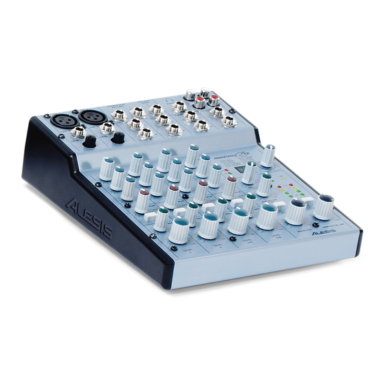
Alesis MultiMix6FX Service Manual
Hide thumbs
Also See for MultiMix6FX:
- Quick start owner's manual (11 pages) ,
- Reference manual (38 pages)
Table of Contents
Advertisement
Quick Links
MultiMix6FX (XA0)
Service Manual
THIS DOCUMENT CONTAINS SENSITIVE
PROPRIETARY INFORMATION. ALL
RECIPIENTS MUST HAVE A CURRENT NON-
DISCLOSURE AGREEMENT ON FILE WITH
DO NOT DISTRIBUTE THIS DOCUMENT IN
WATERMARK DISTRIBUTION
This document has been flagged for watermark
distribution.
service center or distributor, print out a copy onto paper
that has been watermarked for the specific company.
This will allow for document distribution history.
The information in this document contains privileged and confidential information.
It is intended only for the use of those authorized by Alesis. If you are not the
authorized, intended recipient, you are hereby notified that any review,
dissemination, distribution or duplication of this document is strictly prohibited. If
you are not authorized, please contact Alesis and destroy all copies of this
document. You may contact Alesis at support@Alesis.com.
Copyright © 2003 Alesis, LLC
Confidential
ALESIS
P/N: 8-31-0126-A
ATTENTION!
ALESIS, LLC.
ELECTRONIC FORM
Before supplying a printed copy to the
Alesis Service Manual
8-31-0126-A
Advertisement
Table of Contents

Subscribe to Our Youtube Channel
Summary of Contents for Alesis MultiMix6FX
- Page 1 This will allow for document distribution history. The information in this document contains privileged and confidential information. It is intended only for the use of those authorized by Alesis. If you are not the authorized, intended recipient, you are hereby notified that any review, dissemination, distribution or duplication of this document is strictly prohibited.
- Page 2 Your purchase of the Manual shall be for your own ultimate use and shall not be for purposes of resale or other transfer. As the owner of the copyright to the Manual, Alesis does not give you the right to copy the Manual, and you agree not to copy the Manual without the written authorization of Alesis. Alesis has no obligation to provide to you any correction of, or supplement to, the Manual, or any new or superseding version thereof.
- Page 3 ALL REPAIRS DONE BY ANY ENTITY OTHER THAN AN AUTHORIZED ALESIS SERVICE CENTER SHALL BE SOLELY THE RESPONSIBILITY OF THAT ENTITY, AND ALESIS SHALL HAVE NO LIABILITY TO THAT ENTITY OR TO ANY OTHER PARTY FOR ANY REPAIRS BY THAT ENTITY.
- Page 4 The product is exposed to water or excessive moisture, c. The AC power supply plug or cord is damaged, d. The product shows an inappropriate change in performance or does not operate normally, or e. The enclosure of the product has been damaged. Confidential Alesis Service Manual 8-31-0126-A...
-
Page 5: Specifications
SERVICE MANUAL MODEL:MULTIMIX 6 FX Specifications RCA Inputs For the more technical-minded, here are some detailed Tape In Level: -10dBV nominal, +5dBV maximum specifications for the MultiMix’s operating levels. 1/4” Outputs Input Channels Main Mix, Ctrl Room, Mic In Sensitivity Range: -60dBu to -10dBu nominal, +5dBu Ext Aux Send Level: +4dBu nominal, +20dBu maximum... - Page 6 • Control room output level-provides control over the separate control room output • 2-track send and return-lets you mix your audio to tape or other media and to add a tape deck or CD player to the mix • External power supply...
-
Page 7: Disassembly Procedures
DISASSEMBLY PROCEDURES 1. REMOVAL OF TOP PANEL/BOTTOM PANEL (Fig1) (A) TAKE OUT THE 9PCS SCREW FROM WHICH THE TOP PANEL (B) TAKE OUT THE 9PCS SCREW FROM WHICH THE BOTTOM PANEL Fig.1... - Page 8 2. REMOVAL OF MAIN P.C.B (Fig2) (A) REMOVE THE 29 PCS KNOB FROM WHICH THE TOP PANEL (B) REMOVE THE 14 PCS NUT AND 14 PCS WASHER FROM WHICH THE TOP PANEL (C) REMOVE THE 13 PCS SCREW FROM WHICH THE TOP PANEL Fig.2 3.REMOVAL OF POWER P.C.B (Fig.3) (A) REMOVE THE 2 PCS SCREWS FROM THE POWER P.C.B...
-
Page 9: Wiring Diagram
WIRING DIAGRAM (US/EU/UK/AUS NZ/IRAM/JAPAN) -
Page 10: Packing Diagram
PACKING DIAGRAM (US/EU/UK/AUS NZ /IRAM/JAPAN) -
Page 11: Explode Diagram
EXPLODE DIAGRAM (US/EU/UK/AUS NZ / IRAM /JAPAN) SEQUENCIAL NO OF EXPLODE DIAGRAM WILL BE MARKED ON REF. COLUMM OF BOM LIST... - Page 12 ALESIS MultiMix6FX (XA0) SCHEMATIC FILES Confidential Alesis Service Manual 8-31-0126-A...
- Page 15 OUT1 OUT3 OUT2 OUT4 2IN- 4IN+ 2IN+ 4IN- 1IN- 3IN+ 1IN+ 3IN- OUT1 OUT3 OUT2 OUT4 2IN- 4IN+ 2IN+ 4IN- 1IN- 3IN+ 1IN+ 3IN- OUT1 OUT3 OUT2 OUT4 2IN- 4IN+ 2IN+ 4IN- 1IN- 3IN+ 1IN+ 3IN-...
- Page 20 ALESIS MultiMix6FX (XA0) HISTORY Confidential Alesis Service Manual 8-31-0126-A...
- Page 21 ALESIS MultiMix6FX (XA0) Confidential Alesis Service Manual 8-31-0126-A...
- Page 22 MANUAL REFERENCE PE2333404RHP POLYBAG 0.007 PE3636304RHP POLYBAG 0.007 7-81-0182-A FOAM ENDCAP PACKING RIGHT 7-81-0175-A FOAM ENDCAP PACKING LEFT 7-51-1219 SHEET "WELCOME TO ALESIS FAMILY" 5 x 8" 7-91-1002 GEL SILICA 5G PACKET RU1304402 RUBBER SC0306RIBI SCREW TF48033201UL TRANFORMAT WS114009605IN WASHR 5-00-1308...
- Page 23 C7,11,20,21,24,25,27,31,34,37,45,46,55,56,57,58,59 ,60,61,62,63,64,65,66,67,68,69,74,79,83,84,85,89,90 CS104K2505X7R CERAMIC 0.1UF (SMD) ,94,95,98,99,102,103,104,105,108,109,110,111,112, 113,122,123,124,125 C8,9,13,14,15,16,40,41,44,47,48,51,52,53,54,70,75, CS200J5005COG CERAMIC 20P (SMD) 86,87,88,91,92,93,96,97,100,101,106,107,114,116,1 17,118,120,121 CERAMIC 330P (SMD) C2,3,42,43,49,50,72,73,78,80,81,82 CS331J5005COG CERAMIC 47P (SMD) C71,115,119 CS470J5005COG CERAMIC 680P (SMD) C35,36,38,39 CS681J5005COG DIODE D5,6,7,8,17,18,19,20 DIENLL4148SM ELECT 10UF/16V(S) C242 EC10616TS ELECT 10UF/25V C128,130,137,138 EC10625T ELECT 10UF/35V(S) C157...
- Page 24 RESISTOR 3K9 (SMD) R120,137,175,179 RS39218J05 RESISTOR 4K3 (SMD) R177,178 RS43218J05 RESISTOR 470O (SMD) R80,81,83,84,90 RS47118J05 RESISTOR 4K7 (SMD) R31,36,57,61,173,176,198,200,237,238,239,248 RS47218J05 RESISTOR 47K (SMD) R189,192,193 RS47318J05 RESISTOR 510O (SMD) R64,65,66,67 RS51118J05 R21,22,23,34,35,82,87,161,165,186,188,199,203,21 RS51218J05 RESISTOR 5K1 (SMD) 0,211,215,216,229,231,234,235,236,240,241,244 RESISTOR 56O (SMD) R105 RS56018J05 RESISTOR 560O (SMD) R121,125,127,128,138,139...
- Page 25 POWER PCB ASS'Y 9-79-0304 CERAMIC 0.1UF (SMD) C230,231 CS104K2505X7R DIODE D9,10,11,12,13,14,15,16 DIN4002 ZENER DIODE R290 DIZBZX79C47V ELECT 100UF/100V(S) C241 EC107100TS ELECT 100UF/35V C232 EC10735T ELECT 1000UF/35V C233,234 EC10835 ELECT 47UF/100V C237,238 EC476100 ELECT 47UF/25V C235,236 EC47625 ELECT 47UF/50V C239,240 EC47650 IC30 IC7805 IC32...


Need help?
Do you have a question about the MultiMix6FX and is the answer not in the manual?
Questions and answers