Table of Contents
Advertisement
Quick Links
ISSUE 3B-01-2010
PRONAR Sp. z o.o.
17-210 NAREW, UL. MICKIEWICZA 101A, PODLASKIE PROVINCE
tel.:
fax:
OPERATOR'S MANUAL
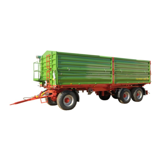
PRONAR T780
Translation of the original instructions
+48 085 681 63 29
+48 085 681 63 81
+48 085 681 63 83
TRAILER
PUBLICATION NO 163N-00000000-UM
+48 085 681 64 29
+48 085 681 63 82
+48 085 682 71 10
www.pronar.pl
Advertisement
Table of Contents

Related Manuals for PRONAR T780


Summary of Contents for PRONAR T780
- Page 1 PRONAR Sp. z o.o. 17-210 NAREW, UL. MICKIEWICZA 101A, PODLASKIE PROVINCE tel.: +48 085 681 63 29 +48 085 681 64 29 +48 085 681 63 81 +48 085 681 63 82 fax: +48 085 681 63 83 +48 085 682 71 10 www.pronar.pl...
- Page 3 The machine is designed to meet obligatory standards, documents and legal regulations currently in force. The instructions describe the basic principles of safe use and operation of T780 trailer. If the information contained in the operating instructions needs clarification then the user should refer for assistance to the sale point where the machine was purchased or to the manufacturer.
- Page 4 Information, descriptions of danger and precautions and also recommendations and orders associated with user safety instructions are marked: and also preceded by the word "DANGER”. Failure to observe the instructions may endanger the machine operator's or other person's health or life. Particularly important information and instructions, the observance of which is essential, are distinguished in the text by the sign: and also preceded either word "ATTENTION".
-
Page 6: Table Of Contents
TABLE OF CONTENTS BASIC INFORMATION IDENTIFICATION INTENDED USE FITTINGS WARRANTY CONDITIONS TRANSPORT ENVIRONMENTAL HAZARDS WITHDRAWAL FROM USE SAFETY IN USE BASIC SAFETY PRINCIPLES PRINCIPLES WHEN TRAVELLING ON PUBLIC ROADS DESCRIPTION OF MINIMAL RISK INFORMATION AND WARNING STICKERS CONSTRUCTION AND PRINCIPLE OF OPERATION TECHNICAL SPECIFICATION CHASSIS LOAD BOX... - Page 7 PROPER USE AND MAINTENANCE OF TYRES 4.16 TECHNICAL MAINTENANCE INSPECTION AND REGULATION OF WHEEL AXLE BEARINGS REGULATION OF MAIN BRAKES REGULATION OF MAIN BRAKES PNEUMATIC SYSTEM OPERATION HYDRAULIC SYSTEM OPERATION LUBRICATION 5.10 INSTALLATION AND DISASSEMBLY OF THE FRAME AND CANVAS COVER 5.14 INSTALLATION AND DISASSEMBLY OF EXTENSION WALLS 5.15 ABSORBER SPRING SYSTEM MAINTENANCE...
-
Page 8: Basic Information
SECTION BASIC INFORMATION IDENTIFICATION INTENDED USE FITTINGS WARRANTY CONDITIONS TRANSPORT ENVIRONMENTAL HAZARDS WITHDRAWAL FROM USE... -
Page 9: Identification
1.1 IDENTIFICATION DRAWING 1.1A LOCATION OF THE DATA PLATE AND SERIAL NUMBER (1) data plate, (2) ALB data plate, (3) serial number The trailer is marked with a data a plate (1) and a serial number (3). The trailer's all identification markings are placed on the front beam of the upper frame, on the right side of the trailer. - Page 10 ITEM MARKING General description and purpose Symbol /Type Year of manufacture Seventeen digit serial number (VIN) Official certificate number Tare weight Maximum gross weight Carrying capacity Maximum hitch load (not applicable) Permissible front axle load Permissible rear axle load The factory numbers of the axle shafts and their types are stamped onto the identity plate secured to the central part of axle shaft beam.
-
Page 11: Intended Use
1.2 INTENDED USE The trailer is designed for transport of harvested crops and agricultural products as well as loose and bulk materials in the vicinity of the farm and on public roads at a maximum speed of 40 km/h. The trailer is also designed for transport of harvested crops and agricultural products transported on pallets. - Page 12 limits stipulated by the road traffic legislation in force in a given country must be observed. The trailer's speed must not, however, be greater than the maximum design speed of 40 km/h. Axle system (axles, wheels and tyres), meet the requirements of agricultural trailers. The trailer user shall familiarise himself with the contents of the operating instructions and comply with them, DANGER...
-
Page 13: Fittings
The minimum power requirements is the tractor's minimum power required to tow a single trailer in medium or difficult terrain conditions. Average or difficult terrain conditions are defined as hard and not marshy ground at an inclination not exceeding 5°. Data indicated in table (1.2) refer standard T780 trailer. 1.3 FITTINGS Standard equipment as well as special fittings and accessories available on order are given in table (1.3). -
Page 14: Warranty Conditions
SD – standard fittings, OP – fittings available at the customer's request 1.4 WARRANTY CONDITIONS PRONAR Sp. z o.o., Narew guarantees the reliable operation of the machine when it is used according to its intended purpose as described in the OPERATOR'S MANUAL. -
Page 15: Transport
1.5 TRANSPORT The trailer is ready for sale in a completely assembled state and does not require packing. Packing is only required for the machine's technical and any extra fittings. The trailer is delivered to the user either transported on a vehicle or, after being attached to a tractor, independently (towed). -
Page 16: Withdrawal From Use
1.7 WITHDRAWAL FROM USE Should the user decide to withdraw the machine fro use, the entire trailer should be taken to a scrap yard approved by local authorities. When spare parts are changed, worn out or damaged parts should be taken to a collection point for recyclable raw materials. Hydraulic oil should be taken to the appropriate facility dealing with the re-use of this type of waste. - Page 17 1.10...
-
Page 18: Safety In Use
SECTION SAFETY IN USE BASIC SAFETY PRINCIPLES PRINCIPLES WHEN TRAVELLING ON PUBLIC ROADS DESCRIPTION OF MINIMAL RISK INFORMATION AND WARNING STICKERS... -
Page 19: Basic Safety Principles
Anyone who uses the machine other than the way intended takes full responsibility on himself for any consequences of this use. • Any modification to the trailer frees PRONAR Narew from any responsibility for damage or detriment to health which may arise as a result. - Page 20 moving by placing wedges or other objects without sharp edges under the trailer's wheels. • People or animals must not be carried. • The trailer and tractor must not be attached if the hydraulic oil in the two machines is of different types.
- Page 21 • Cut-off valve in the hydraulic tipping system limits the tipping angle of the load box when tipped to the sides. The length of the control cable controlling this valve is factory adjusted by the manufacturer and must not be changed when the trailer is used.
- Page 22 • Before beginning repair works on hydraulic or pneumatic installations reduce oil or air pressure. • In the event of injuries being caused by pressurised hydraulic oil, contact a doctor immediately. Hydraulic oil may find its way under the skin and cause infections. In the event of contact of oil with eye, rinse with large quantity of water and in the event of the occurrence of irritation consultant a doctor.
- Page 23 • During the warranty period, any repairs may only be carried out by a Warranty Service authorised by the manufacturer. • Should it be necessary to change individual parts, use only original parts or those indicated by the manufacturer. Non-adherence to these requirements may cause danger to the health and the user's and other people's lives, and also damage the machine.
-
Page 24: Principles When Travelling On Public Roads
• Exercise caution when climbing on top of the load box. Climbing on top of the load box is possible through the fenced platform, ladders placed on the front wall, while extension and folding steps attached inside the load box. 2.2 PRINCIPLES WHEN TRAVELLING ON PUBLIC ROADS •... -
Page 25: Description Of Minimal Risk
2.3 DESCRIPTION OF MINIMAL RISK Pronar Sp. z o. o. in Narew has made every effort to eliminate the risk of accidents. There is, however, a certain minimal risk which could lead to an accident, and this is connected mainly with the actions described below: •... -
Page 26: Information And Warning Stickers
• cleaning, maintenance and technical checks of the trailer. The minimal risk may be kept to a minimum by following the recommendations below: • prudent and unhurried operation of the machine, • sensible application of the remarks and recommendations contained in the OPERATING INSTRUCTIONS, •... - Page 27 ITEM SAFETY SYMBOL DESCRIPTION Before beginning servicing or repairs, switch off engine and remove key from ignition Before climbing on the ladder in order to perform maintenance or repair is inside the load box, switch of engine and remove key from ignition.
- Page 28 ITEM SAFETY SYMBOL DESCRIPTION Keep a safe distance from electric power lines during unloading. Hydraulic tipper system Switching between hydraulic circuits I & II - air pressure in tyres depends on tyres used - not shown on figure (2.2A), stickers are applied in the vicinity of hydraulic sockets and three-way hydraulic valve 2.11...
- Page 29 DRAWING 2.2A STICKER LOCATIONS Labelling in line with table 2.1 „Information and warning stickers” 2.12...
-
Page 30: Construction And Principle Of Operation
SECTION CONSTRUCTION AND PRINCIPLE OF OPERATION TECHNICAL SPECIFICATION CHASSIS LOAD BOX WORKING BRAKE PARKING BRAKE HYDRAULIC TIPPER SYSTEM ELECTRICAL SYSTEM, WARNING SIGNS AND INDICATORS... -
Page 31: Technical Specification
3.1 TECHNICAL SPECIFICATION TABLE 3.1 T780 TRAILER BASIC TECHNICAL SPECIFICATION CONTENTS UNIT DATA Dimensions Total length 9 614 Total width 2 548 Total height 3 102 Axle track 1 900 Axle base 4 760 Internal load box dimensions: - length... -
Page 32: Chassis
CONTENTS UNIT DATA Maximum design speed km/h Hydraulic oil demand - Technical specifications for a standard configuration with a spare wheel (no fenced platform, canvas cover or frame) The maximum speed of the trailer on public roads is 30 km/h in Poland (pursuant to Road Traffic Act of June 20th 1997, art. 20). - Page 33 (4), taper leaf springs (5) and the drawbar (6). Drawbar is fixed to the rotator's frame using pins. DRAWING 3.1A TRAILER CHASSIS (1) lower frame, (2) wheel axle, (3) lights support beam, (4) rotator frame, (5) taper leaf spring (6) drawbar, (7) telescopic cylinder, (8) rear under-run protective device, (9) spare wheel holder, (10) toolbox...
-
Page 34: Load Box
The height of drawbar attachment can be adjusted by moving the bracket fixing the spring to the drawbar. Tandem axle suspension with absorber springs is mounted in the rear part of the frame – figure (3.2A). It is composed of rocker arm (1) and taper leaf springs (2). The whole assembly is connected using pins (3), (4) and (5). - Page 35 DRAWING 3.3A LOAD BOX (1) upper frame, (2) load box walls, (3) wall extensions, (4) fenced platform, (5) front wall ladder, (6) front wall extension ladder, (7) side pull-off mechanism, (8) linking cable, (9) lateral grain chute...
- Page 36 DRAWING 3.4A LOAD BOX REAR WALL (1) grain chute, (2) slide gate, (3) rear wall pull-off mechanism Upper frame is mounted on the lower frame and articulated sockets secured with pins, which are pivot points when tipping the load box in three directions Wall ladder (5) and wall extension ladder (6) are mounted to the front wall and wall extension of the load box –...
-
Page 37: Working Brake
3.4 WORKING BRAKE DRAWING 3.5A BRAKE SYSTEM WITH AUTOMATIC REGULATOR (1) supply conduit, (2) control connector, (3) control valve, (4) automatic brake force regulator, (5) air filter, (6) 40 L air tank, (7) 60 L air tank, (8) drain valve, (9) diaphragm actuator 30”, (10) diaphragm actuator 24”, (11) relay valve, (12) air tank to control connector The trailer is equipped with double conduit pneumatic system with automatic brake force... -
Page 38: Parking Brake
regulator (3.5A) Working brake is activated from the tractor driver's cab by pressing on the brake pedal in the tractor. The function of the control valve (3) - figure (3.5A) is the operation of the trailer's brakes simultaneously when tractor's brakes are applied Furthermore, in case of an inadvertent disconnection of the conduit between the trailer and the tractor, the control valve will automatically activate trailer's brakes. -
Page 39: Hydraulic Tipper System
DRAWING 3.6A PARKING BRAKE (1) steel cable, (2) guide rollers, (3) brake crank mechanism, (4) handbrake release 3.6 HYDRAULIC TIPPER SYSTEM Hydraulic tipping system serves in automatic unloading of trailer by tipping the load box to the rear or sideways. The trailers hydraulic tipping system is supplied with oil from the tractor's hydraulic system. -
Page 40: Electrical System, Warning Signs And Indicators
hitched to the tractor. Three-way valve (7) – (3.7A) is used to activate these circuits. This valve's lever can the placed in two positions: • 1 - trailer's tipping circuit opened - circuit (A), • 2 - second trailer's tipping circuit opened – circuit (B). DRAWING 3.7A HYDRAULIC TIPPING SYSTEM DIAGRAM (1) telescopic cylinder, (2) plug, (3) cut-off valve, (4) control cable, (5) guide roller, (6) socket, (7) three-way valve... - Page 41 DRAWING 3.8A POSITIONING OF ELECTRICAL ELEMENTS AND REFLECTIVE LIGHTS (1),(2) front position lamp, (3) 7-pin socket, (4) white reflective light (5), (6) rear light combination group, (7), (8) clearance light, (9) license plate light, (10) rear reflective triangle, (11) orange lateral reflective light, (12) slow-moving vehicle warning sign Lateral clearance lamps are available as additional accessories.
- Page 42 components and reflective lights is shown on figure (3.9A). Figure (3.10A) presents electrical system diagram including additional accessories (lateral clearance lights). DRAWING 3.9A ELECTRICAL SYSTEM DIAGRAM (ZP), (ZL) rear lamp group, (TOP), (TOL) rear clearance light, (GP), (GT) seven-pin socket, (OTP), (OTL) license plate light, (PP), (PL) front position lamp, (OBL), (OBP) lateral clearance light 3.13...
- Page 43 3.14...
-
Page 44: Correct Use
SECTION CORRECT USE PREPARING FOR WORK BEFORE FIRST USE CHECKING THE TRAILER'S TECHNICAL CONDITION ATTACHING TO TRACTOR LOADING TRANSPORTING LOADS UNLOADING DISCONNECTING FROM TRACTOR PROPER USE AND MAINTENANCE OF TYRES... -
Page 45: Preparing For Work Before First Use
4.1 PREPARING FOR WORK BEFORE FIRST USE The trailer is supplied to the user in a completely assembled state and does not require additional mounting operations of machine sub-assemblies. The manufacturer guarantees that the trailer is fully operational and has been checked according to quality control procedures and is ready for normal use. -
Page 46: Checking The Trailer's Technical Condition
identified and rectified. If a fault cannot be rectified or the repair could void the guarantee, please contact retailer for additional clarifications. ATTENTION! Non-adherence to the recommendations contained in the instructions or improper use of trailer may cause damage to the machine. The technical condition prior to starting use may not give rise to any reservation. -
Page 47: Attaching To Tractor
DESCRIPTION SERVICE OPERATION FREQUENCY Lubricate elements according to Lubrication guidelines presented in section "Lubrication". Degree of tightening of road wheel Torque values should be according to nuts table (5.5). ATTENTION! The trailer must not be used when not in working order. Prior to connecting individual system conduits the user must familiarise himself with the content of the tractors operating instructions and observe all manufacturer's recommendations. - Page 48 DRAWING 4.1A ADJUSTING DRAWBAR HEIGHT (1) tension spring, (2) bracket • reverse tractor, connect drawbar eye with appropriate tractor hitch, secure the hitch against inadvertent disconnection of the trailer • connect electrical leads to the tractor as well as braking and tipping system conduit tubes to appropriate tractor sockets, •...
-
Page 49: Loading
4.4 LOADING Before beginning loading it is necessary to make certain that the load box side walls and slide gates are properly closed and secured. The trailer must be positioned to travel forwards and be hitched to the tractor. Loading should only take place, when trailer is placed on flat level surface and hitched to tractor. - Page 50 VOLUME WEIGHT TYPE OF MATERIAL kg/m3 potash salt 1,100 – 1 200 superphosphate 850 – 1 440 basic slag phosphate 2,000 – 2 300 potassium sulphate 1,200 – 1 300 kainite 1,050 – 1 440 milled lime fertiliser 1,250 - 1 300 Building materials: cement 1,200 –...
- Page 51 VOLUME WEIGHT TYPE OF MATERIAL kg/m3 dry stored clover 40 - 60 cut dry stored clover 80 - 140 dry straw in round bales 8 - 15 damp straw in round bales 15 - 20 cut damp straw in bulk trailer 50 - 80 cut dry straw in bulk trailer 20 - 40...
- Page 52 VOLUME WEIGHT TYPE OF MATERIAL kg/m3 molasses 1,350 – 1 450 silage (pit silo) 650 – 1 050 hay silage (tower silo) 550 - 750 Seeds and grains: beans 750 - 850 mustard 600 - 700 peas 650 - 750 lentils 750 - 860 runner beans...
- Page 53 materials shown in table (4.2). It is necessary to pay particular attention not to overload the trailer. Light materials with a large volume, maybe loaded even above the edge of the load box extension walls paying special attention to trailer stability. Regardless of the type of load carried, the user is obliged to secure it in such a manner that the load is unable to spread and cause contamination of the road.
-
Page 54: Transporting Loads
4.5 TRANSPORTING LOADS When travelling on public or private roads, respect the road traffic regulations, exercise caution and prudence. Listed below are the key guidelines for driving the tractor and trailer combination. • Before moving off make sure that there are no bystanders, especially children, near the trailer or the tractor. -
Page 55: Unloading
importance because loaded trailer's centre of gravity is higher, which reduces safety. Driving near ditches or channels is dangerous as there is a risk of the wheels sliding down the slope or the slope collapsing. • Speed must be sufficiently reduced before making a turn or driving on an uneven road or a slope. - Page 56 • after unloading a lot where there is an old box, clean the residual material from the load box edge, the walls and wall extensions, • close and secure the walls and wall extensions or chute opening, • before moving off make sure that tipping pin are in correct position, i.e. with the handle facing downward and secured with cotter pin - see figure (4.2A).
- Page 57 Rear load box wall is equipped with chute slide gate (1) and chute opening (2) (additional accessory) – figure (4.3A) which is used for unloading of loose materials. Chute design allows very accurate dosing of the material to packaging (sacks, boxes etc). The opening gap can be controlled using a lever (4).
-
Page 58: Disconnecting From Tractor
DANGER Tipping the load box must be done on hard and level ground. Use only original pins with a handle and securing cotter pin. Using third-party pins could damage the trailer. Tipping pins must be correctly interlocked. When opening load box sidle wall locks take particular care, because of the pressure of the load on the wall. - Page 59 checks should be made after the first use, after the first journey with a load and then every 6 months. The above actions should be repeated individually if a wheel has been removed from the wheel axle. • Regularly check and maintain correct pressure in tyres according to instructions (especially if trailer is not used for a longer period).
-
Page 60: Technical Maintenance
SECTION TECHNICAL MAINTENANCE INSPECTION AND REGULATION OF WHEEL AXLE BEARINGS REGULATION OF MAIN BRAKES REGULATION OF MAIN BRAKES PNEUMATIC SYSTEM OPERATION HYDRAULIC SYSTEM OPERATION LUBRICATION INSTALLATION AND DISASSEMBLY OF THE FRAME AND CANVAS COVER INSTALLATION AND DISASSEMBLY OF EXTENSION WALLS ABSORBER SPRING SYSTEM MAINTENANCE STORAGE TRAILER PREPARATION FOR END OF SEASON... -
Page 61: Inspection And Regulation Of Wheel Axle Bearings
5.1 INSPECTION AND REGULATION OF WHEEL AXLE BEARINGS In newly purchased trailer, after covering a distance of 100 km, while during further use – after 6 months of vehicle use check and regulate wheel axle bearings when needed. Worn or damaged bearing should be replaced. - Page 62 DRAWING 5.2A LIFTING JACK SUPPORT POINT (1) wheel axle, (2) U bolt, (3) lower frame If slack is felt, it is necessary to adjust bearing. Unusual sounds coming from bearing may be symptoms of excess wear, dirt or damage. In such an event the bearing, together with sealing ring, should be replaced with new parts.
-
Page 63: Regulation Of Main Brakes
Bearings replacement, lubrication and repairs connected with brake system and wheel axle should be entrusted to specialist service provider. Inspection of slack and technical condition of wheel axle bearings must be performed after the first month of use, and then every 6 months of trailer use. 5.2 REGULATION OF MAIN BRAKES Brakes regulation is necessary when: •... - Page 64 DRAWING 5.3A REGULATION OF MAIN BRAKES (1) expander arm, (2) expander shaft, (3) regulation screw TABLE 5.1 MAIN BRAKE BRAKING FORCE MAIN BRAKE BRAKING FORCE UNIT 124.5 Regulation should be conducted separately for each wheel. After proper brake regulation, at °...
- Page 65 The main brake system should be inspected annually and in case of need should be regulated. 5.3 REGULATION OF MAIN BRAKES Regulation of parking brake should be conducted in the event of: • stretching of cable, • loosening of parking brake cable clamps •...
-
Page 66: Pneumatic System Operation
The parking brake system should be inspected annually and in case of need should be regulated. 5.4 PNEUMATIC SYSTEM OPERATION As a part of trailer maintenance, it is necessary to conduct inspection of individual pneumatic systems, giving particular attention to places of all connections. Tightness of the system should be checked at nominal pressure in system of approximately 600 kPa (6.0 kg/cm If conduits, seals or other system elements are damaged, compressed air will escape in these damaged places with a characteristic hiss. - Page 67 body should be carefully washed out and blown through with compressed air. Assembly should be done in reverse order. DRAWING 5.4A AIR FILTER (1) securing slide lock, (2) air filter cover DANGER Before proceeding to dismantle filter, reduce pressure in supply conduit. While disengaging filter slide gate, hold cover with other hand.
-
Page 68: Hydraulic System Operation
DRAWING 5.5A CONDUIT CONNECTIONS (1) rubber seal, (2) security cover It is recommended that seals are preserved with silicon preparation, specified for rubber elements every six months. Contact of the seals with fuel, lubricants being petroleum derivatives, paints etc., causes rapid ageing of the material from which they are made. Connection should be inspected every time before connecting trailer to tractor. - Page 69 sub assemblies is equally required in each instance of mechanical damage. In the event of confirmation of damage of hydraulic ram cylinders they must be replaced or repaired. In such an event the whole set of seals must be changed. Hydraulic conduits should be replaced after 4 years of trailer use.
-
Page 70: Lubrication
oil with skin wash the place of contact with water and soap. Do not apply organic solvents (petrol, kerosene). Contaminated clothing should be changed to prevent access of oil to skin. In the event of contact of oil with eye, rinse with large quantity of water and in the event of the occurrence of irritation consultant a doctor. - Page 71 NUMBER OF TYPE OF GREASING NAME GREASING GREASE FREQUENCY POINTS Slide gate guides 2 or 6 Silicone 1 month Slide gate pins in the rear Silicone 1 month wall Wall pins and locks Silicone 1 month Tipping ram cylinder ball permanent 6 months bearing...
- Page 72 DRAWING 5.6A CHASSIS GREASING POINTS 5.13...
- Page 73 DRAWING 5.7A LOAD BOX GREASING POINTS 5.14...
-
Page 74: Installation And Disassembly Of The Frame And Canvas Cover
Trailer greasing should be performed with the aid of a manually or foot operated grease gun, filled with generally available permanent grease. Absorber plates should be lubricated using an agent having both anticorrosion and lubricating properties, it is recommended to apply on outer surfaces very thin layer of grease. -
Page 75: Installation And Disassembly Of Extension Walls
ATTENTION! Assembly and disassembly of the frame should be carried out with the use of appropriate platforms, ladders or when standing on a ramp. These tools must be in good condition to fully protect the persons working on them against falling. Work should be performed by at least two persons. -
Page 76: Absorber Spring System Maintenance
5.9 ABSORBER SPRING SYSTEM MAINTENANCE Maintenance of the absorber spring system involves periodical lubrication of the suspension in locations indicated in table (5.4) and described in the Lubrication section and periodical monitoring of the technical condition of absorber plates. The surfaces between the absorber plates should be protected using silicone spray with anticorrosion and lubrication properties. -
Page 77: Tightening Torque For Nut And Bolt Connections
Lubricate elements according to guidelines presented in section "Lubrication". 5.12 TIGHTENING TORQUE FOR NUT AND BOLT CONNECTIONS Unless other tightening parameters are given, during maintenance repair work apply appropriate torque to tightening nut and bolt connections. Recommended tightening torque of most frequently applied nut and bolt connections are given in table (5.5). -
Page 78: Faults And Means Of Remedying Them
DRAWING 5.8A BOLT WITH METRIC THREAD (1) bolt strength class, (d) thread diameter 5.13 FAULTS AND MEANS OF REMEDYING THEM TABLE 5.6 FAULTS AND MEANS OF REMEDYING THEM FAULT CAUSE REMEDY Brake system pneumatic Connect brake conduit. conduits not connected Damaged pneumatic Replace system connection conduit... -
Page 79: List Of Bulbs
FAULT CAUSE REMEDY Worn brake linings Change brake shoes Hydraulic tipping system Connect the conduit conduit not connected Hydraulic circuits control Set the valve the position 1 Tipping the load box and valve set to position 2 not possible Check the routing of the control Cut-off valve stuck or the cable and if the cut-off valve is cable for controlling the cut-... - Page 80 5.21...
- Page 81 NOTES ………………………………………………………………………………………………………………………………….. ………………………………………………………………………………………………………………………………….. ………………………………………………………………………………………………………………………………….. ………………………………………………………………………………………………………………………………….. ………………………………………………………………………………………………………………………………….. ………………………………………………………………………………………………………………………………….. ………………………………………………………………………………………………………………………………….. ………………………………………………………………………………………………………………………………….. ………………………………………………………………………………………………………………………………….. ………………………………………………………………………………………………………………………………….. ………………………………………………………………………………………………………………………………….. ………………………………………………………………………………………………………………………………….. ………………………………………………………………………………………………………………………………….. ………………………………………………………………………………………………………………………………….. ………………………………………………………………………………………………………………………………….. ………………………………………………………………………………………………………………………………….. ………………………………………………………………………………………………………………………………….. ………………………………………………………………………………………………………………………………….. ………………………………………………………………………………………………………………………………….. ………………………………………………………………………………………………………………………………….. ………………………………………………………………………………………………………………………………….. ………………………………………………………………………………………………………………………………….. ………………………………………………………………………………………………………………………………….. ………………………………………………………………………………………………………………………………….. ………………………………………………………………………………………………………………………………….. …………………………………………………………………………………………………………………………………..
- Page 82 ………………………………………………………………………………………………………………………………….. ………………………………………………………………………………………………………………………………….. ………………………………………………………………………………………………………………………………….. ………………………………………………………………………………………………………………………………….. ………………………………………………………………………………………………………………………………….. ………………………………………………………………………………………………………………………………….. ………………………………………………………………………………………………………………………………….. ………………………………………………………………………………………………………………………………….. ………………………………………………………………………………………………………………………………….. ………………………………………………………………………………………………………………………………….. ………………………………………………………………………………………………………………………………….. ………………………………………………………………………………………………………………………………….. ………………………………………………………………………………………………………………………………….. ………………………………………………………………………………………………………………………………….. ………………………………………………………………………………………………………………………………….. ………………………………………………………………………………………………………………………………….. ………………………………………………………………………………………………………………………………….. ………………………………………………………………………………………………………………………………….. ………………………………………………………………………………………………………………………………….. ………………………………………………………………………………………………………………………………….. ………………………………………………………………………………………………………………………………….. ………………………………………………………………………………………………………………………………….. ………………………………………………………………………………………………………………………………….. ………………………………………………………………………………………………………………………………….. ………………………………………………………………………………………………………………………………….. ………………………………………………………………………………………………………………………………….. ………………………………………………………………………………………………………………………………….. ………………………………………………………………………………………………………………………………….. ………………………………………………………………………………………………………………………………….. …………………………………………………………………………………………………………………………………..
- Page 83 Tire sizes TRAILER VERSION TIRE 385/65 R 22.5 160 K 425/65 R 22.5 160 F T780 445/65 R 22.5 170 F 500/60 R 22.5 165 A8 560/60 R 22.5 161 D - disc wheel 11.75x22.5" ET=-30 - disc wheel 13.00x22.5" ET=0 - disc wheel 14.00x22.5"...
Need help?
Do you have a question about the T780 and is the answer not in the manual?
Questions and answers