Advertisement
Quick Links
REVISION 1A-05-2014
PRONAR Sp. z o.o.
17-210 NAREW, UL. MICKIEWICZA 101A, WOJ. PODLASKIE
tel.:
fax:
USER MANUAL
AGRICULTURAL TRAILER
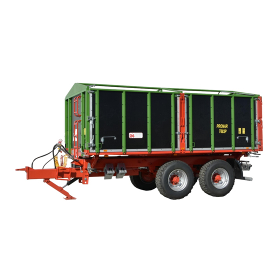
PRONAR T683P
TRANSLATION OF ORIGINAL MANUAL
+48 085 681 63 29
+48 085 681 63 81
+48 085 681 63 83
PUBLICATION NUMBER 395N-00000000-UM
+48 085 681 64 29
+48 085 681 63 82
+48 085 682 71 10
www.pronar.pl
Advertisement

Related Manuals for PRONAR T683P


Summary of Contents for PRONAR T683P
- Page 1 PRONAR Sp. z o.o. 17-210 NAREW, UL. MICKIEWICZA 101A, WOJ. PODLASKIE tel.: +48 085 681 63 29 +48 085 681 64 29 +48 085 681 63 81 +48 085 681 63 82 fax: +48 085 681 63 83 +48 085 682 71 10 www.pronar.pl...
- Page 3 This will guarantee safe and trouble-free operation of the machine. The machine was constructed in accordance with applicable standards, documents and current legal regulations. The User Manual describes the basic principles of safe use and operation of Pronar T683P agricultural trailer.
- Page 4 SYMBOLS USED IN THE MANUAL Information, descriptions of hazards and precautions as well as instructions and orders related to safe use in the manual are marked with: and preceded by the word „DANGER”. Failure to comply with these recommendations may endanger the health or life of persons operating the machine or unauthorized bystanders.
- Page 5 DESIGNATION OF DIRECTIONS IN THE MANUAL Left side – the left-hand side of the observer facing the machine in the forward direction. Right side – the right-hand side of the observer facing the machine in the forward direction. THE SCOPE OF SERVICE ACTIVITIES The maintenance activities described in the manual are marked with the sign: The result of the maintenance / adjustment activity or remarks concerning the performed activities is marked with the sign:...
- Page 7 CONTENTS 1 GENERAL IDENTIFICATION 1.1.1 IDENTIFICATION OF TRAILER 1.1.2 IDENTIFICATION OF DRIVING AXLES 1.1.3 LIST OF FACTORY NUMBERS INTENDED USE EQUIPMENT TERMS OF WARRANTY 1.10 TRANSPORT 1.11 1.5.1 TRUCKING 1.11 1.5.2 USER'S TRANSPORT 1.13 THREAT TO THE ENVIRONMENT 1.13 WITHDRAWAL FROM USE 1.14 2 SAFETY OF USE GENERAL TERMS OF SAFETY...
- Page 8 3 CONSTRUCTION AND PRINCIPLE OF OPERATION TECHNICAL CHARACTERISTICS CONSTRUCTION OF A TRAILER 3.2.1 CHASSIS 3.2.2 LOAD BOX 3.2.3 SERVICE BRAKE 3.2.4 HYDRAULIC TIPPING SYSTEM 3.12 3.2.5 HYDRAULIC SYSTEM OF THE SCISSOR SUPPORT 3.14 3.2.6 PARKING BRAKE 3.15 3.2.7 LIGHTING INSTALLATION 3.16 4 RULES OF USE PREPARING FOR WORK BEFORE FIRST USE...
- Page 9 5 TECHNICAL SUPPORT PRELIMINARY INFORMATION DRIVING AXLE SERVICE 5.2.1 PRELIMINARY INFORMATION 5.2.2 CHECKING THE CLEARANCE OF THE AXLE BEARINGS 5.2.3 ADJUSTING THE CLEARANCE OF THE AXLE BEARINGS 5.2.4 WHEEL ASSEMBLY AND DISASSEMBLY, CHECKING NUT TIGHTNESS 5.2.5 AIR PRESSURE CONTROL, ASSESSMENT OF TECHNICAL CONDITION OF TIRES AND STEEL WHEELS 5.2.6 BRAKE LINING THICKNESS CONTROL 5.10...
- Page 10 ELECTRICAL SYSTEM SERVICE AND WARNING ELEMENTS 5.27 5.5.1 PRELIMINARY INFORMATION 5.27 LUBRICATION OF THE TRAILER 5.28 CONSUMABLES 5.33 5.7.1 HYDRAULIC OIL 5.33 5.7.2 LUBRICANTS 5.34 CLEANING THE TRAILER 5.34 STORAGE 5.36 5.10 TIGHTENING TORQUE FOR NUT AND BOLT CONNECTIONS 5.36 5.11 ADJUSTMENT OF THE DRAWBAR POSITION 5.38 5.12 TROUBLESHOOTING...
- Page 11 CHAPTER GENERAL...
- Page 12 Pronar T683P CHAPTER 1 1.1 IDENTIFICATION 1.1.1 IDENTIFICATION OF TRAILER FIGURE 1.1. Location of nameplate and serial number (1) nameplate, (2) serial number The trailer was marked with a nameplate (1) and the serial number (2) placed on a rectangular field painted in gold. The data plate is located on the front beam of the upper frame and the serial number is on the lower frame longitudinal member - figure (1.1).
- Page 13 CHAPTER 1 Pronar T683P TABLE 1.1. Nameplate markings ITEM MARKING General information and function Trailer symbol / type Year of trailer production Seventeen-digit serial number (VIN) Certificate approval number The trailer's karb weight Permissible gross weight Capacity Permissible load on the coupling device...
- Page 14 Pronar T683P CHAPTER 1 1.1.3 LIST OF FACTORY NUMBERS VIN Number FRONT AXIS SERIAL NUMBER REAR AXIS SERIAL NUMBER ADVICE If you need to order spare parts or if you have problems with it, it is very often necessary to provide the serial numbers of the part or VIN of the trailer, so it is recommended to write these numbers in the fields below.
- Page 15 CHAPTER 1 Pronar T683P CAUTION The trailer may not be used for purposes other than those for which it is intended. In particular, it is forbidden to: • Transport of people, animals, dangerous materials, aggressive loads as a result of chemical reactions to trailer structural elements (causing corrosion of steel, damaging paint coverings, dissolving plastic elements, destroying rubber elements, etc.),...
- Page 16 Pronar T683P CHAPTER 1 • accident prevention, • comply with road traffic regulations and transport regulations in force in the country in which the trailer is used, • get acquainted with the contents of the farm tractor instruction manual and comply with its recommendations, •...
- Page 17 CHAPTER 1 Pronar T683P CONTENT UNIT REQUIREMENTS Hydraulic tipping system Hydraulic oil L HL 32 Lotos Maximum system pressure bar / MPa 200 / 20 Oil demand Electrical system Electrical system voltage Connection socket 7 poles in accordance with ISO 1724...
- Page 18 Pronar T683P CHAPTER 1 TABLE 1.4. Second trailer requirements CONTENT UNIT REQUIREMENTS Permissible total weight of a two- 18,000 axle trailer Braking system - connectors Pneumatic 1 - wire connector in accordance with ISO 1728 Pneumatic 2 - wire connector in accordance with ISO 1728...
- Page 19 CHAPTER 1 Pronar T683P TABLE 1.5. Trailer equipment EQUIPMENT • User manual • Warranty Card • Wheel chocks • Tarpaulin frame • Hydraulic scissor support • Side of the left portal • Side of the right portal • Side of the left portal 3 chimney dampers •...
- Page 20 CHAPTER 1 1.4 TERMS OF WARRANTY PRONAR Sp. z o.o. in Narew guarantees smooth operation of the machine when it is used in accordance with the technical and operational conditions described in the USER MANUAL. Deadline for completion of repairs is specified in the WARRANTY CARD.
- Page 21 CHAPTER 1 Pronar T683P warranty or not. Detailed warranty conditions are given in the WARRANTY CARD attached to the newly purchased machine. ADVICE You should require the seller to carefully fill out the Warranty Card and complaint coupons. The lack of e.g. date of sale or point of sale stamp exposes the user to not accept any complaints.
- Page 22 Pronar T683P CHAPTER 1 securing material used. Chocks, wooden beams or other elements without sharp edges should be placed under the trailer wheels, protecting the machine against rolling. Trailer wheel blocks must be nailed to the load platform planks of the car or secured in another way preventing their movement.
- Page 23 CHAPTER 1 Pronar T683P During reloading work, particular attention should be paid so as not to damage the machine equipment components and the paint coating. The tare weight of the trailer, standard equipment, in running order, was given in table (3.1).
- Page 24 Pronar T683P CHAPTER 1 DANGER Used hydraulic oil or collected residues mixed with absorbent material should be stored in a precisely marked container. Do not use food packaging for this purpose. Oil which has been used up or is unsuitable for further use due to the loss of its properties is recommended to be stored in its original packaging in the same conditions as described previously.
- Page 25 CHAPTER SAFETY OF USE...
- Page 26 Pronar T683P CHAPTER 2 2.1 GENERAL TERMS OF SAFETY 2.1.1 TRAILER USE • Before using the trailer, the user should carefully read the content of this document WARRANTY CARD. During their operation, recommendations contained therein must be observed. • The trailer may only be used and operated by persons authorized to drive agricultural tractors with a trailer.
- Page 27 CHAPTER 2 Pronar T683P • The trailer user is obliged to become familiar with the construction, operation and principles of safe trailer operation. 2.1.2 CONNECTING AND DISCONNECTING THE TRAILER TO THE TRACTOR • It is forbidden to connect the trailer to the tractor if it does not meet the requirements set by the Manufacturer (minimum power requirement of the tractor, inadequate connections, etc.) - compare table (1.2) AGRICULTURAL TRACTOR...
- Page 28 Pronar T683P CHAPTER 2 • Before coupling the trailer, make sure that both machines are technically sound. • Take special care when connecting the machine. • When connecting nobody may be between the trailers. The person who helps aggregate the machine should stand in a place outside the hazardous area and be visible at all times by the tractor operator.
- Page 29 CHAPTER 2 Pronar T683P replacement packaging resistant to hydrocarbons. Replacement containers must be accurately described and properly stored. • It is forbidden to store hydraulic oil in packaging intended for food storage. • Rubber hydraulic conduits must be replaced every 4 years regardless of their technical condition.
- Page 30 Pronar T683P CHAPTER 2 • Before raising the load box, the tipping pins should be placed on the intended unloading side. Check the correct installation of the pins. • Keep a safe distance from overhead power lines when lifting the box.
- Page 31 CHAPTER 2 Pronar T683P • The admissible design speed should not be exceeded. • Adjust speed to prevailing conditions. • It is forbidden to leave the machine unsecured. The trailer disconnected from the tractor must be blocked with the parking brake and secured against rolling with wedges or other elements without sharp edges placed under the vehicle wheels.
- Page 32 Pronar T683P CHAPTER 2 • Before driving, check if the bolts connecting the load box to the lower frame and wall bolts are secured against falling out. Check rear wall slide protection. Make sure that all walls and extensions are properly closed.
- Page 33 CHAPTER 2 Pronar T683P FIGURE 2.2. Mounting location for the slow-moving vehicle sign (1) distinguishing sign • A triangular plate for slow moving vehicles should be placed on the rear wall, if the trailer is the last vehicle in the set - Figure (2.2). The triangular plate should be placed in a specially prepared holder riveted to the rear wall of the load box.
- Page 34 Pronar T683P CHAPTER 2 2.1.7 TIRES • When working with tires, the trailer should be immobilized with the parking brake and secured against rolling by placing wedges under the wheels. The wheel can be dismantled only when the trailer is not loaded.
- Page 35 CHAPTER 2 Pronar T683P • Any modification of the trailer releases PRONAR Narew from any liability for damage or injury. • Climbing the trailer is possible only when the trailer is absolutely stationary and the tractor engine is switched off. Tractor and trailer should be secured with parking brake and wedges should be placed under trailer wheels.
- Page 36 Pronar T683P CHAPTER 2 are poisonous to humans and animals. Welding work should be carried out in a well-lit and ventilated room. • During welding work pay attention to flammable or fusible elements (elements of pneumatic, electric, hydraulic systems, elements made of plastic). If there is a risk of ignition or damage, they must be removed or covered with non-flammable material before welding.
- Page 37 Pronar T683P 2.2 DESCRIPTION OF RESIDUAL RISK Pronar Sp. z o. o. o. in Narew made every effort to eliminate the risk of an accident. However, there is some residual risk that can lead to an accident and is primarily associated with the following activities: •...
- Page 38 Pronar T683P CHAPTER 2 • a ban on being on the machine while driving, loading or unloading. 2.3 INFORMATION AND WARNING STICKERS The trailer is marked with information and warning stickers mentioned in table (2.1). The arrangement of symbols is shown in figure (2.3). The machine user is obliged to ensure that the inscriptions, warning and information symbols placed on the trailer are legible throughout the entire period of use.
- Page 39 CHAPTER 2 Pronar T683P STICKER MEANING Before starting any servicing or repair work, switch off the tractor engine and remove the ignition key. Secure the tractor cab against unauthorized access. Before starting any servicing or repair work, switch off the tractor engine and remove the ignition key.
- Page 40 Pronar T683P CHAPTER 2 STICKER MEANING Danger of being crushed. It is forbidden to carry out repair or maintenance works under a loaded and/or unsupported load box. Regularly check the tightness of wheel nuts and other bolted connections. Lubricate the trailer...
- Page 41 CHAPTER 2 Pronar T683P STICKER MEANING Position of the valve controlling the operation of the hydraulic tipping system. Information on hitching the trailer to the upper transport hitch only. Tire pressure. Manufacturer's website address. The hose supplying the hydraulic system of the scissor support.
- Page 42 Pronar T683P CHAPTER 2 FIGURE 2.3. Arrangement of information and warning stickers 2.18...
- Page 43 CHAPTER CONSTRUCTION AND PRINCIPLE OF OPERATION...
- Page 44 Pronar T683P CHAPTER 3 3.1 TECHNICAL CHARACTERISTICS TABLE 3.1. Basic technical data CONTENT UNIT Overall dimensions of the trailer Total length 6 800 Overall width 2 550 Overall height 2 790 Internal dimensions of box Length 5 100 Width 2 420...
- Page 45 CHAPTER 3 Pronar 683P 3.2 CONSTRUCTION OF A TRAILER 3.2.1 CHASSIS The trailer chassis consists of the units specified in figure (3.1). The lower frame (1) is a welded structure made of steel sections. The basic load-bearing element are two longitudinal members connected with crossbars.
- Page 46 Pronar T683P CHAPTER 3 FIGURE 3.1. Trailer chassis (1) lower frame, (2) tipping cylinder seat, (3) lighting beam, (4) road axle, (5) wheel, (6) string, (7) rear beam, (8) front crossbar, (9) hitch, (10) box support, (11) trailer support, (12) fender,...
- Page 47 CHAPTER 3 Pronar 683P 3.2.2 LOAD BOX The load box of the trailer - figure (3.2) - consists of: upper frame (1) with a welded steel floor, front wall (2), rear wall (3), right side walls with extensions (5) forming a tilting system, and side walls ( 4) on the left side (tilt and fold system).
- Page 48 Pronar T683P CHAPTER 3 FIGURE 3.2. Load box (1) upper frame, (2) front wall, (3) rear wall, (4) portal side wall, (5) right side wall with extension, (6) central post, (7) front lock, (8) rear lock, (9) lower ladder, (10) upper ladder, (11) balcony, (12) side plates of the chute system, (13) frame, (14) tarpaulin.
- Page 49 CHAPTER 3 Pronar 683P FIGURE 3.3. Load box rear wall (1) gate valve, (2) chute of the discharge chute, (3) rear wall chute plate, (4) closing of the left rear wall, (5) closing the right rear wall, (6) side step 3.2.3 SERVICE BRAKE...
- Page 50 Pronar T683P CHAPTER 3 FIGURE 3.4. Construction and diagram of the dual-line pneumatic braking system (1) air tank, (2) control valve, (3) brake force regulator, (4) pneumatic cylinder, (5) hose connector (black), (6) air filter, (7) air tank control connector, (8 ) pneumatic actuator control...
- Page 51 CHAPTER 3 Pronar 683P FIGURE 3.5. Construction and diagram of the dual-conduit pneumatic braking system with a manual braking force regulator (1) air tank, (2) control valve, (3) brake force regulator, (4) pneumatic actuator, (5) hose connector (red), (6) hose connector (yellow), (7) air filter, ( 8) air tank control joint,...
- Page 52 Pronar T683P CHAPTER 3 FIGURE 3.6. Construction and diagram of the dual-conduit pneumatic braking system with an automatic braking force regulator (1) air tank, (2) control valve, (3) brake force regulator, (4) pneumatic actuator, (5) hose connector (red), (6) hose connector (yellow), (7) air filter, ( 8) air tank control joint,...
- Page 53 CHAPTER 3 Pronar 683P The service brake (pneumatic or hydraulic) is activated from the driver's cab by pressing the tractor brake pedal. The task of the control valve (2) - figure ((3.4), (3.5) and (3.6) , is to activate the trailer brakes simultaneously with the tractor brake applied. In addition, in the event of an unforeseen disconnection of the hose between the trailer and the tractor, the control valve automatically applies the machine's brake.
- Page 54 Pronar T683P CHAPTER 3 FIGURE 3.8. Control valve and braking force regulator (1) control valve, (2) braking force regulator, (3) trailer brake release button when parking, (4) regulator selection lever, (A) ‘UNLOADED’ position, (B) ‘HALF LOAD’ position, (C) 'FULL LOAD’ position 3.2.4 HYDRAULIC TIPPING SYSTEM...
- Page 55 CHAPTER 3 Pronar 683P FIGURE 3.9. Construction and diagram of the hydraulic tipping system (1) telescopic cylinder, (2) three-way valve, (3) shut-off valve, (4) quick coupler (5) socket, (6) control cable, (7) guide roller, (8), (9) information stickers A three-way valve (2) is used to turn on these circuits - see figure (3.9). The lever on this valve can occupy 2 positions: •...
- Page 56 Pronar T683P CHAPTER 3 A sticker (13) has been placed on the connecting pipe, in the vicinity of the plug (4), which identifies the hydraulic feed pipe of the tipping system. CAUTION The cut-off valve (3) - figure (3.9) limits the tipping angle of the load box when tilted to the sides and to the rear.
- Page 57 CHAPTER 3 Pronar 683P Hydraulic system of support - figure (3.10) is used for automatic unfolding and folding of the support leg (3). This is done by extending or retracting the piston rod of the hydraulic cylinder (4). The support system is fed through the conduit (1) with oil from the tractor's hydraulic system.
- Page 58 Pronar T683P CHAPTER 3 FIGURE 3.11. Parking brake construction (1) crank mechanism, (2) cable, (3) guide roller, parking brake lever, (4) expander arm 3.2.7 LIGHTING INSTALLATION TABLE 3.2. List of electrical components markings SYMBOL FUNCTION Multifunctional rear right lamp Multifunctional rear left lamp...
- Page 59 CHAPTER 3 Pronar 683P SYMBOL FUNCTION Multifunctional right lamp Multifunctional left lamp Multifunctional left rear lamp Multifunctional right rear lamp FIGURE 3.12. Electrical system schematic diagram Designations according to the table (3.2) The trailer's electrical installation is adapted to be supplied from a 12 V DC source.
- Page 60 Pronar T683P CHAPTER 3 FIGURE 3.13. Arrangement of electrical system components and reflectors - rear view (1) left rear multi-purpose lamp, (2) right rear multi-purpose lamp, (3) license plate lamp, (4) triangular reflector, (5) rear 7-pin socket, (6) rear clearance lamp TABLE 3.3.
- Page 61 CHAPTER 3 Pronar 683P FIGURE 3.14. Arrangement of electrical system components and reflectors - forward view (1) front position lamp, (2) front 7-pin socket, (3) white reflector, (4) orange reflector 3.19...
- Page 62 Pronar T683P CHAPTER 3 3.20...
- Page 63 CHAPTER RULES OF USE...
- Page 64 Pronar T683P CHAPTER 4 4.1 PREPARING FOR WORK BEFORE FIRST USE 4.1.1 CHECKING THE TRAILER AFTER DELIVERY The manufacturer ensures that the trial is fully functional, has been checked in accordance with control procedures and is approved for use. However, this does not release the user from the obligation to check the vehicle after delivery and before first use.
- Page 65 CHAPTER 4 Pronar T683P 4.1.2 PREPARATION OF THE TRAILER FOR THE FIRST CONNECTION Preparation Check all trailer lubrication points, if necessary lubricate machine as recommended in chapter 5. Check the tightness of the nuts securing the road wheels. Drain the air reservoir in the braking system.
- Page 66 Pronar T683P CHAPTER 4 ADVICE Service activities: connecting / disconnecting from the tractor, adjusting the drawbar position, tipping the load box, etc. are described in detail further in the manual, in chapters 4 and 5. The trailer may only be hitched when all preparatory activities and technical inspection have been successful.
- Page 67 CHAPTER 4 Pronar T683P 4.2 CONNECTING AND DISCONNECTING THE TRAILER TO THE TRACTOR The trailer may be connected to an agricultural tractor, if all connections (electrical, pneumatic, hydraulic) and the hitch on the agricultural tractor are in accordance with the trailer manufacturer's requirements.
- Page 68 Pronar T683P CHAPTER 4 FIGURE 4.1. Trailer support (1) scissor support, (2) actuator, (3), (4) cables, (5), (6) information decals Connect the pneumatic system conduits (applies to single conduit systems): Connect the pneumatic conduit marked black with the black socket in the tractor.
- Page 69 CHAPTER 4 Pronar T683P DANGER During coupling it is forbidden to stand bystanders between the trailer and the tractor. The agricultural tractor operator when connecting the machine should take particular care during work and make sure that unauthorized persons are not in the danger zone during coupling.
- Page 70 Pronar T683P CHAPTER 4 By controlling the tractor hydraulic manifold levers, set the drawbar eye at such a height that it is possible to unlock and disconnect the trailer. Switch off the tractor engine. Close the tractor cabin and secure it against unauthorized access.
- Page 71 CHAPTER 4 Pronar T683P 4.3 CONNECTING AND DISCONNECTING OF A SECOND TRAILER A second trailer may only be connected if it is a machine built on a two-axle chassis and if it meets all the requirements of chapter 1. Hitching a second trailer with a set requires experience in steering an agricultural tractor with a trailer.
- Page 72 Pronar T683P CHAPTER 4 FIGURE 4.2. Rear hitch (1) hitch body, (2) hitch pin, (3) chain with a securing pin, (4) handle for lifting the automatic hitch Disconnecting of the second trailer Block the tractor and trailer with parking brake.
- Page 73 CHAPTER 4 Pronar T683P CAUTION It is forbidden to connect a second trailer built on a chassis other than in a two-axle system. The manual rear hitch is designed only for towing the second trailer, the maximum permissible weight of which does not exceed 13,500 kg.
- Page 74 Pronar T683P CHAPTER 4 CAUTION The load should be evenly distributed in the load box. The trailer's maximum carrying capacity must not be exceeded. Due different density of materials, the use of the total capacity of the load box may exceed the allowable capacity of the trailer.
- Page 75 CHAPTER 4 Pronar T683P VOLUMETRIC WEIGHT TYPE OF MATERIAL kg/m Building Materials: cement 1,200 – 1,300 dry sand 1,350 – 1,650 wet sand 1,700 – 2,050 solid bricks 1,500 – 2,100 brick blocks 1,000 – 1,200 stone 1,500 – 2,200...
- Page 76 Pronar T683P CHAPTER 4 VOLUMETRIC WEIGHT TYPE OF MATERIAL kg/m dry straw cut on a collecting trailer 50 - 90 dry straw cut in a haystack 40 - 100 pressed straw (low compaction) 80 - 90 pressed straw (high compaction)
- Page 77 CHAPTER 4 Pronar T683P VOLUMETRIC WEIGHT TYPE OF MATERIAL kg/m 650 - 750 lentil 750 - 860 bean 780 - 870 barley 600 - 750 Shamrock 700 - 800 grass 360 - 500 maize 700 - 850 wheat 720 - 830...
- Page 78 Pronar T683P CHAPTER 4 Loose materials Loading of loose materials is usually carried out with the help of loaders or conveyors, possibly by manual loading. Loose materials must not protrude beyond the outline of walls or extensions. After loading, the load layer should be evenly distributed over the entire surface of the load box.
- Page 79 CHAPTER 4 Pronar T683P that can be transported with an agricultural trailer, provided that they are transported in appropriate packaging and in the quantities provided for in the ADR agreement. DANGER If it is necessary to transport permitted hazardous materials, please read the regulations for the transport of hazardous materials in force in your country and the ADR agreement in detail.
- Page 80 Pronar T683P CHAPTER 4 DANGER Trailer overloading, inefficient loading and securing of loads are the most common causes of accidents during transport. The load must be arranged in such a way that it does not threaten the stability of the trailer and does not hinder driving.
- Page 81 CHAPTER 4 Pronar T683P DANGER The trailer is not designed for transporting people, animals or hazardous materials (except for loads specified in chapter 4.4). The placement of load must not cause overloading of the running gear or the trailer hitch system.
- Page 82 Pronar T683P CHAPTER 4 machine breakdown, stop at the side of the road without endangering other road users and mark the stopping place in accordance with traffic regulations. • When travelling on public roads, the trailer must be marked with a slow-moving vehicle warning sign located on the rear wall of the load box, if the trailer is the last vehicle in the set.
- Page 83 CHAPTER 4 Pronar T683P • The trailer is adapted for driving on slopes up to a maximum of 5 . Moving the trailer over slopes may cause the trailer to overturn as a result of loss of stability. Prolonged driving on sloping ground creates a risk of loss of braking efficiency.
- Page 84 Pronar T683P CHAPTER 4 FIGURE 4.3. Locking of the tipping pins (1) tipping pin I, (2) tipping pin II, (3) tipping pin holder When opening the side walls together with the extensions (applies to the trailer with portal walls on the right side), first open the middle wall locks (13) - see figure (4.5), and then unlock the lower locking hooks.
- Page 85 CHAPTER 4 Pronar T683P Lever (1) - figure (4.4) is used to unlock the bolts of the right and left front side walls. set the control lever for the hydraulic tipping system circuits to position 1 - tipping the first trailer, using the divider lever in the driver's cab cause the load box to tilt, Unload the load by tilting the load box using a hydraulic cylinder.
- Page 86 Pronar T683P CHAPTER 4 FIGURE 4.4. Opening the left portal wall of the cargo box (1) front side wall closing lever, (2) lower side wall lock, (3) upper side wall lock, (4) hinge, (5) lock, (6) handle, (7) lock slot...
- Page 87 CHAPTER 4 Pronar T683P FIGURE 4.5. Arrangement of locks and bolts of the trailer walls (1) rear wall lever, (2) left (right) rear wall lever, (3) rear wall bottom lock, (4) left rear wall bottom lock, (5) left rear wall top lock, (6) upper wall lock rear, (7) middle lower left lock, (8) middle upper left lock, (9) bottom lock of the left front wall, (10) upper lock of the left front wall.
- Page 88 Pronar T683P CHAPTER 4 DANGER Tilting of the load box may only be performed on firm and level ground. Only original pins with a handle should be used. The use of non-original pins may damage the trailer. Tipping pins must be properly locked.
- Page 89 CHAPTER 4 Pronar T683P as standard equipment, the portal walls are on the left side of the trailer, in order to open portal walls, unlock the lever (2) - figure (4.5) and the lever (1) figure (4.4). open the upper middle (8) and lower (7) locks located in the central column (3) on the left side of the trailer.
- Page 90 Pronar T683P CHAPTER 4 unload the load by tilting the load box using a telescopic cylinder. It is forbidden to start and jerking with the lifted load box in order to empty it. lower and close the hydraulic wall, paying particular attention to its proper locking, lower the cargo box all the way down.
- Page 91 CHAPTER 4 Pronar T683P FIGURE 4.7. Chute (1) chute slide gate, (2) chute, (3) lever, (4) locking screw Be especially careful when unloading bulky materials. It is forbidden to tip the load box on uneven and wet terrain, as well as start and jerk the trailer during unloading. Bulky materials are usually loads that are difficult to discharge, so be careful and calm when working.
- Page 92 Pronar T683P CHAPTER 4 4.7 USE OF TIRES • When working with tires, the trailer should be secured against rolling by placing wedges or other elements without sharp edges under the wheels. The wheel can be dismantled only when the trailer is not loaded.
- Page 93 CHAPTER 4 Pronar T683P 4.8 OPERATION OF THE OVERRUN PROTECTION In the additional equipment of the trailer, it is possible to install two pairs of underrun protection, both covers are tiltable. They fulfil a very important role in road safety and therefore should take care of their condition and completeness.
- Page 94 Pronar T683P CHAPTER 4 FIGURE 4.8. Left underrun protection (1) left underrun protection, (2) barrier holder bracket, (3) clamp, (4) latch, (5) securing pin 4.32...
- Page 95 CHAPTER TECHNICAL SUPPORT...
- Page 96 Pronar T683P CHAPTER 5 5.1 PRELIMINARY INFORMATION When using the trailer, it is necessary to constantly check the technical condition and perform maintenance procedures that will allow the vehicle to be kept in good technical condition. Therefore, the trailer user is obliged to perform all maintenance and adjustment activities specified by the Manufacturer.
- Page 97 CHAPTER 5 Pronar T683P • other road axle repairs, can be performed by specialized workshops. DANGER It is forbidden to use a trailer with a damaged driving axle. 5.2.2 CHECKING THE CLEARANCE OF THE AXLE BEARINGS FIGURE 5.1. Hoist support point...
- Page 98 Pronar T683P CHAPTER 5 Place blocking chocks under the trailer wheel that will not be lifted. Ensure that the trailer will not roll during inspection. Raise the wheel (located on the opposite side of the placed wedges). The jack should be placed between the U bolts (2) - - figure (5.1) securing the axle (1) to the leaf springs.
- Page 99 CHAPTER 5 Pronar T683P Checking the clearance of the axle bearings: • after covering the first 1,000 km, • before intensive use of the trailer, • every 6 months of use or 25,000 km. Check the technical condition of the hub cover, replace if necessary. Check of the bearing looseness can only be carried out when the trailer is connected to the tractor and the loading box is empty.
- Page 100 Pronar T683P CHAPTER 5 Gently tap the hub with a rubber or wooden hammer. The wheel should rotate smoothly, without jams and no noticeable resistance, not from rubbing the shoes against the brake drum. Adjusting of the bearing looseness can only be carried out when the trailer is connected to the tractor and the loading box is empty.
- Page 101 CHAPTER 5 Pronar T683P Loosen the wheel nuts according to the order given in figure (5.3). Place the jack and raise the trailer. Remove the wheel. Wheel mounting Clean the axle pins and nuts from contamination. Do not lubricate the threads of the nut and stud.
- Page 102 Pronar T683P CHAPTER 5 FIGURE 5.3. The order of the nuts tightening (1) - (10) order of tightening the nuts, (L) wrench length, (F) user weight • After first use of the trailer (one-time inspection). • Every 2– 3 hours of driving (during the first month of use of the trailer) •...
- Page 103 CHAPTER 5 Pronar T683P CAUTION Wheel nuts must not be tightened with impact wrenches, due to the danger of exceeding the permissible tightening torque, which may result in breaking the connection thread or breaking the hub pin. The highest tightening accuracy is obtained with a torque wrench. Before starting work, make sure that the correct torque value is set.
- Page 104 Pronar T683P CHAPTER 5 Pressure control and visual inspection of steel wheels: • every 1 month of use, • in case of emergency. 5.2.6 BRAKE LINING THICKNESS CONTROL While using the trailer, the drum brake friction linings will wear out. While using the trailer, the drum brake friction linings will wear out.
- Page 105 CHAPTER 5 Pronar T683P The brake lining thickness should be checked every 6 months. ADVICE The minimum thickness of the linings is 5mm. 5.2.7 ADJUSTMENT OF MECHANICAL BRAKES Significant lining wear increases the stroke of the brake cylinder piston and reduces braking performance.
- Page 106 Pronar T683P CHAPTER 5 FIGURE 5.5. Construction of axle brake (1) expander arm, (2) expander shaft, (3) adjustment screw, (4) brake cylinder, (5) cylinder piston rod, (6) cylinder fork, (7) fork pin The control consists in measuring the extension length of each piston rod during braking at a standstill.
- Page 107 CHAPTER 5 Pronar T683P FIGURE 5.6. Brake adjustment principle (1) cylinder piston, (2) cylinder diaphragm, (3) expander arm, (4) adjustment screw, (5) fork of the cylinder, (6) pin position of the fork, (7) support of the cylinder, (A) mark on the piston rod...
- Page 108 Pronar T683P CHAPTER 5 Check that the cylinder piston moves freely and within the full nominal range. Check that the actuator ventilation openings are not clogged with dirt and that there is no water or ice inside. Check the correct mounting of the actuator.
- Page 109 CHAPTER 5 Pronar T683P FIGURE 5.7. Service brake adjusting (1) brake crank mechanism, (2) handbrake cable, (3) guide roller, (4) expander arm, (5) U-shaped clamp, (6) clamp nut, (7) shackle Adjustment of parking brake cable tension should be carried out in the case of: •...
- Page 110 Pronar T683P CHAPTER 5 Unscrew the brake crank bolt (1) as far as possible. Loosen the nuts (6) of U-shaped clamps (5) at the ends of the cable to be replaced. Disassemble the appropriate shackles (7) on the ends of the cable to be replaced.
- Page 111 CHAPTER 5 Pronar T683P Unscrew the screw of the brake mechanism (1) maximally - figure (5.7), (counter clockwise). Loosen the nuts (6) of the bow clamps (5) on the handbrake cable. Tighten the cable and tighten the clamps. The length of the parking brake cable should be selected so that when the service and parking brake is completely released, the cable is loose and hangs 1-2 cm.
- Page 112 Pronar T683P CHAPTER 5 5.3.2 TIGHTNESS CHECK AND VISUAL INSPECTION OF THE INSTALLATION Checking the tightness of pneumatic systems Hitch trailer to tractor. The tractor and trailer should be immobilized with the parking brake. Additionally, place wedges under the wheel of the trailer.
- Page 113 CHAPTER 5 Pronar T683P Visual assessment of the system When checking for leaks, pay attention to the technical condition and degree of cleanliness of the system components. Contact of pneumatic conduits, seals etc. with oil, grease, gasoline etc. may damage them or accelerate the aging process. Bent, permanently deformed, cut or frayed wires are only eligible for replacement.
- Page 114 Pronar T683P CHAPTER 5 FIGURE 5.9. Air filter (1) securing slide, (2) filter cover Cleaning the air filter (filters), • every 3 months of use. The scope of service activities Reduce pressure in the supply line. The pressure in the pipe can be reduced by pushing the plug of the pneumatic connection as far as it will go.
- Page 115 CHAPTER 5 Pronar T683P DANGER Before removing the filter, reduce the pressure in the supply line. When removing the filter slide, hold the cover with the other hand. Point the filter cover away from you. 5.3.4 AIR TANK DRAINAGE FIGURE 5.10. Air tank drainage...
- Page 116 Pronar T683P CHAPTER 5 Air tank drainage: • every 7 months of use. 5.3.5 CLEANING THE DRAINAGE VALVE DANGER Bleed the air tank before removing the drain valve. The scope of service activities Fully reduce the pressure in the air reservoir.
- Page 117 CHAPTER 5 Pronar T683P 5.3.6 CLEANING AND MAINTAINING PNEUMATIC CONNECTORS AND SOCKETS DANGER Faulty and dirty trailer connections can cause the braking system to malfunction. A damaged connector body or socket for connecting a second trailer qualifies them for replacement. In the event of damage to the cover or gasket, replace these elements with new, functional ones.
- Page 118 Pronar T683P CHAPTER 5 FIGURE 5.11. Assembly of pneumatic hose (1) plug-in nipple, (2) pneumatic conduit TIGHTENING PART NAME THREAD TORQUE (Nm) M22x1.5 M14x1.5 Pneumatic system connector M16x1.5 M18x1.5 M22x1.5 5.4 HYDRAULIC SYSTEM OPERATION 5.4.1 PRELIMINARY INFORMATION Work related to the repair, replacement or regeneration of hydraulic system components (tipping cylinder, valves, etc.) should be entrusted to specialized workshops that have the...
- Page 119 CHAPTER 5 Pronar T683P • checking system tightness and visual inspection of the system, • checking the technical condition of the hydraulic connectors. DANGER It is forbidden to perform tipping with a faulty hydraulic tipping system. It is forbidden to drive with faulty hydraulic system of the support.
- Page 120 Pronar T683P CHAPTER 5 Checking for leaks: • after the first week of use, • every 12 months of use. 5.4.3 CHECKING THE TECHNICAL CONDITION OF THE HYDRAULIC CONNECTORS AND SOCKETS Hydraulic connections and sockets intended for connecting a second trailer must be technically sound and kept clean.
- Page 121 CHAPTER 5 Pronar T683P 5.5 ELECTRICAL SYSTEM SERVICE AND WARNING ELEMENTS 5.5.1 PRELIMINARY INFORMATION Work related to the repair, replacement or regeneration of electrical installation components should be entrusted to specialized workshops that have appropriate technologies and qualifications to perform this type of work.
- Page 122 Pronar T683P CHAPTER 5 Check the correct installation of the triangular plate holder for slow moving vehicles. Before travelling on a public road, make sure that the tractor has a reflective warning triangle. Electrical system check: • each time when connecting the trailer.
- Page 123 CHAPTER 5 Pronar T683P TABLE 5.2. Trailer lubrication schedule ITEM LUBRICATION POINT Hub bearings Drawbar eye The camshaft bushing Drawbar bolt Tipping cylinder seats and cylinder sling Ball bearing of the tipping cylinder Parking brake mechanism Parking brake guide roll pin...
- Page 124 Pronar T683P CHAPTER 5 ITEM LUBRICATION POINT Scissor support cylinder bearings Chute guides Chute tie pins Extension hinges Wall lock Front locking mechanism pin Rear locking mechanism pin Bolts and wall locks lubrication periods - M month, D - day TABLE 5.3.
- Page 125 CHAPTER 5 Pronar T683P FIGURE 5.12. Trailer lubrication points, part 1 5.31...
- Page 126 Pronar T683P CHAPTER 5 FIGURE 5.13. Trailer lubrication points, part 2 5.32...
- Page 127 CHAPTER 5 Pronar T683P 5.7 CONSUMABLES 5.7.1 HYDRAULIC OIL It is absolutely necessary to observe that the oil in the trailer's hydraulic system and the tractor's hydraulic system must be of the same type. If different types of oil are used, make sure that both hydraulic means can be mixed together.
- Page 128 Pronar T683P CHAPTER 5 5.7.2 LUBRICANTS For heavily loaded parts, it is recommended to use lithium grease with the addition of molybdenum disulphide (MOS ) or graphite. For less loaded components, it is recommended to use general-purpose machine greases that contain anti-corrosive additives and are highly resistant to water washout.
- Page 129 CHAPTER 5 Pronar T683P points lubricating trailers, etc. High pressure water jet may cause mechanical damage to these components. • For cleaning and maintenance of plastic surfaces, it is recommended to use clean water or specialized preparations intended for this purpose.
- Page 130 Pronar T683P CHAPTER 5 5.9 STORAGE • It is recommended that the trailer be stored indoors or under a roof. • If the machine will not be used for a long period of time, it must be protected against the effects of weather conditions, especially those that cause corrosion of steel and accelerate the aging of tires.
- Page 131 CHAPTER 5 Pronar T683P FIGURE 5.14. Metric thread screw (1) strength class, (d) thread diameter The hydraulic hoses should be tightened with a torque of 50 - 70 Nm. TABLE 5.5. Tightening torques for screw connections 10.9 METRIC THREAD Md [Nm]...
- Page 132 Pronar T683P CHAPTER 5 5.11 ADJUSTMENT OF THE DRAWBAR POSITION Adjustment of the position of the drawbar eye (1) is performed by changing the position of the eye in relation to the drawbar faceplate (2). FIGURE 5.15. Adjusting the position of the drawbar eye...
- Page 133 CHAPTER 5 Pronar T683P 5.12 TROUBLESHOOTING TABLE 5.6. Faults and how to remove them FAULT CAUSE REMOVAL METHOD Brake system lines not Connect the brake lines (applies to connected pneumatic system). Parking brake applied Release the parking brake. Pneumatic connection lines Trouble with Replace.
- Page 134 Pronar T683P CHAPTER 5 FAULT CAUSE REMOVAL METHOD Insufficient tractor hydraulic pump performance, tractor Check the hydraulic pump on the tractor. hydraulic pump defective. Check the cylinder piston rod (bending, corrosion), check the cylinder for leaks Damaged or dirty actuator (piston rod seal), repair or replace the cylinder if necessary.
- Page 135 NOTES …………………………………………………………………………………………………………… …………………………………………………………………………………………………………… …………………………………………………………………………………………………………… …………………………………………………………………………………………………………… …………………………………………………………………………………………………………… …………………………………………………………………………………………………………… …………………………………………………………………………………………………………… …………………………………………………………………………………………………………… …………………………………………………………………………………………………………… …………………………………………………………………………………………………………… …………………………………………………………………………………………………………… …………………………………………………………………………………………………………… …………………………………………………………………………………………………………… …………………………………………………………………………………………………………… …………………………………………………………………………………………………………… …………………………………………………………………………………………………………… …………………………………………………………………………………………………………… …………………………………………………………………………………………………………… …………………………………………………………………………………………………………… …………………………………………………………………………………………………………… …………………………………………………………………………………………………………… …………………………………………………………………………………………………………… …………………………………………………………………………………………………………… ……………………………………………………………………………………………………………...
- Page 136 …………………………………………………………………………………………………………… …………………………………………………………………………………………………………… …………………………………………………………………………………………………………… …………………………………………………………………………………………………………… …………………………………………………………………………………………………………… …………………………………………………………………………………………………………… …………………………………………………………………………………………………………… …………………………………………………………………………………………………………… …………………………………………………………………………………………………………… …………………………………………………………………………………………………………… …………………………………………………………………………………………………………… …………………………………………………………………………………………………………… …………………………………………………………………………………………………………… …………………………………………………………………………………………………………… …………………………………………………………………………………………………………… …………………………………………………………………………………………………………… …………………………………………………………………………………………………………… …………………………………………………………………………………………………………… …………………………………………………………………………………………………………… …………………………………………………………………………………………………………… …………………………………………………………………………………………………………… …………………………………………………………………………………………………………… …………………………………………………………………………………………………………… …………………………………………………………………………………………………………… …………………………………………………………………………………………………………… …………………………………………………………………………………………………………… ……………………………………………………………………………………………………………...
- Page 137 TYPE OF TRAILER FRONT / REAR AXLE 385/65 R 22.5 160 F 385/65 R 22.5 TL 425/65 R 22.5 168 F T683P 425/65 R22.5 TL 500/60 R 22.5 165 A8 550/60 R 22.5 163 A8 560/60 R 22.5 161 D - disc wheel 11.75 x 22.5’’...
Need help?
Do you have a question about the T683P and is the answer not in the manual?
Questions and answers