Table of Contents
Advertisement
Quick Links
TRANSLATION OF THE ORIGINAL COPY OF THE MANUAL
ISSUE 2A-01-2010
PRONAR Sp. z o.o.
17-210 NAREW, UL. MICKIEWICZA 101A, PODLASKIE PROVINCE
tel.:
fax:
OPERATOR'S MANUAL
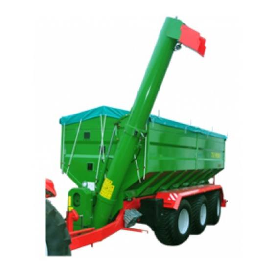
AGRICULTURAL TRAILER
PRONAR T743
+48 085 681 63 29
+48 085 681 63 81
+48 085 681 63 83
PUBLICATION NO 205N-00000000-UM
+48 085 681 64 29
+48 085 681 63 82
+48 085 682 71 10
www.pronar.pl
EN
Advertisement
Table of Contents

Related Manuals for PRONAR T743


Summary of Contents for PRONAR T743
- Page 1 PRONAR Sp. z o.o. 17-210 NAREW, UL. MICKIEWICZA 101A, PODLASKIE PROVINCE tel.: +48 085 681 63 29 +48 085 681 64 29 +48 085 681 63 81 +48 085 681 63 82 fax: +48 085 681 63 83 +48 085 682 71 10 www.pronar.pl...
- Page 3 The machine is designed to meet obligatory standards, documents and legal regulations currently in force. The manual describes the basic safety rules and operation of Pronar T743 trans-shipment trailer. If the information contained in the Operator's Manual needs clarification then the user should refer for assistance to the sale point where the machine was purchased or to the Manufacturer.
- Page 4 SYMBOLS APPEARING IN THIS OPERATOR'S MANUAL Information, descriptions of danger and precautions and also recommendations and prohibitions associated with user safety instructions are marked: and also preceded by the word "DANGER”. Failure to observe the instructions may endanger the machine operator's or other person's health or life. Particularly important information and instructions, the observance of which is essential, are distinguished in the text by the sign: and also preceded by the word "ATTENTION".
- Page 5 DIRECTIONS USED IN THIS OPERATOR'S MANUAL Left side – side to the left hand of the operator facing in the direction of machine's forward travel. Right side – side to the right hand of the operator facing in the direction of machine's forward travel.
-
Page 7: Table Of Contents
CONTENTS BASIC INFORMATION 1.1 IDENTIFICATION 1.1.1 TRAILER IDENTIFICATION 1.1.2 AXLE IDENTIFICATION 1.1.3 LIST OF FACTORY NUMBERS 1.2 PROPER USE 1.3 OPTIONAL EQUIPMENT 1.4 WARRANTY TERMS 1.5 TRANSPORT 1.5.1 TRANSPORT ON VEHICLE 1.5.2 INDEPENDENT TRANSPORT BY THE USER 1.11 1.6 ENVIRONMENTAL HAZARDS 1.11 1.7 WITHDRAWAL FROM USE 1.12... - Page 8 2.3 INFORMATION AND WARNING DECALS 2.15 DESIGN AND OPERATION 3.1 TECHNICAL SPECIFICATION 3.2 CHASSIS 3.2.1 DRAWBAR HITCHING EYE 3.2.2 TRAILER PARKING STAND 3.3 LOAD BOX 3.4 FRONT CONVEYOR 3.5 FRONT CHAIN TRANSMISSION 3.10 3.6 GEAR WHEEL TRANSMISSION 3.12 3.7 REAR CHAIN TRANSMISSION 3.13 3.8 MAIN BRAKE 3.14...
- Page 9 4.8 UNLOADING 4.13 4.9 DISCONNECTING FROM TRACTOR 4.16 4.10 PROPER USE AND MAINTENANCE OF TYRES 4.17 4.11 WEIGHER OPERATION 4.17 4.11.1 MOUNTING INDICATOR 4.17 4.11.2 STANDARD WORK 4.19 MAINTENANCE 5.1 PRELIMINARY INFORMATION 5.2 TRAILER INSPECTIONS OPERATION NO. 1 - CHECKING WHEEL AXLE BEARINGS 5.2.1 OPERATION NO.
- Page 10 5.2.16 OPERATION NO. 16 – INSPECTION OF TIGHTNESS OF FRONT CHAIN TRANSMISSION (II STAGE) 5.27 5.2.17 OPERATION NO.17 – INSPECTION OF TIGHTNESS OF REAR CHAIN TRANSMISSION 5.29 5.2.18 OPERATION NO. 18 – CHANGE OIL IN FRONT GEAR WHEEL TRANSMISSION 5.30 5.2.19 OPERATION NO.
-
Page 12: Basic Information
SECTION BASIC INFORMATION... -
Page 13: Identification
Pronar T743 SECTION 1 1.1 IDENTIFICATION 1.1.1 TRAILER IDENTIFICATION FIGURE 1.1 Location of the data plate and serial number (1) data plate, (2) serial number The trailer is marked with the data plate (1), located on the right frame brace and the factory number (2) located on a gold painted rectangle. -
Page 14: Axle Identification
SECTION 1 Pronar T743 TABLE 1.1 Markings on data plate ITEM MARKING General description and purpose Symbol /Type Year of manufacture Seventeen digit serial number (VIN) Official certificate number Tare weight Maximum gross weight Carrying capacity Permissible hitching system loading... -
Page 15: List Of Factory Numbers
MIDDLE FIXED AXLE SERIAL NUMBER REAR STEERING AXLE SERIAL NUMBER 1.2 PROPER USE The trailer Pronar T743 is constructed according to current safety requirements and engineering standards. The brake system and the light and indicator system meet the requirements of road traffic regulations. - Page 16 Using it as intended involves all actions connected with the safe and proper operation and maintenance of the machine. In connection with this the user is obliged to: • carefully read the OPERATOR'S MANUAL of Pronar T743 trailer and the WARRANTY BOOK and conform with the recommendations contained in these documents, •...
- Page 17 Pronar T743 SECTION 1 TABLE 1.2 AGRICULTURAL TRACTOR'S REQUIREMENTS CONTENTS UNIT REQUIREMENTS Brake system Pneumatic system 1 – conduit sockets compliant with PN- ISO 1728:2007 sockets compliant with PN- Pneumatic system 2 – conduit ISO 1728:2007 Nominal pressure of the system 1 p.
-
Page 18: Optional Equipment
SECTION 1 Pronar T743 The trailer may only be used by persons, who: • are familiar with the contents of this publication and with the contents of the agricultural tractor Operator's Manual, • have been trained in trailer operation and safe operation, •... -
Page 19: Warranty Terms
Information concerning tyres is provided at the end of this publication in ANNEX A. 1.4 WARRANTY TERMS PRONAR Sp. z o.o., Narew guarantees the reliable operation of the machine when it is used according to its intended purpose as described in the OPERATOR'S MANUAL. The repair period is specified in the WARRANTY BOOK. - Page 20 SECTION 1 Pronar T743 • brake shoes, • bulbs and LED lamps, • seals, • bearings. The warranty service only applies to such cases as: mechanical damage, which is not the user's fault, factory defects of parts, etc. In the event of damage arising from: •...
-
Page 21: Transport
Pronar T743 SECTION 1 1.5 TRANSPORT The trailer is ready for sale completely assembled and does not require packing. Packing is only required for the machine's technical documentation and any extra fittings. The trailer is delivered to the user either transported on a vehicle or, after being attached to a tractor, independently (trailer towed with a tractor). -
Page 22: Independent Transport By The User
SECTION 1 Pronar T743 IMPORTANT! When being road transported on a motor vehicle the trailer must be mounted on the vehicle's platform in accordance with the transport safety requirements and the regulations. Driver of the vehicle should be particularly careful during travel. This is due to the vehicle's centre of gravity shifting upwards when loaded with the machine. - Page 23 Pronar T743 SECTION 1 toxicity of organisms living in the aquatic environment. The formation of a film of oil on the water may be the direct cause of physical action on organism, perhaps causing change of oxygen values in the water because of lack of direct contact of air with the water. An oil leak into water reservoirs may however lead to a reduction of the oxygen content.
-
Page 24: Withdrawal From Use
SECTION 1 Pronar T743 1.7 WITHDRAWAL FROM USE In the event of decision by the user to withdraw the trailer from use, comply with the regulations in force in the given country concerning withdrawal from use and recycling of machines withdrawn from use. Before commencing dismantling, totally remove the oil from the hydraulic system and reduce air pressure completely in the pneumatic brake system (e.g. - Page 25 Pronar T743 SECTION 1 1.14...
-
Page 26: Safety Advice
SECTION SAFETY ADVICE... -
Page 27: Basic Safety Rules
Pronar T743 SECTION 2 2.1 BASIC SAFETY RULES 2.1.1 USE OF TRAILER • Before using the trailer, the user must carefully read this Operator's Manual and the WARRANTY BOOK. When operating the machine, the operator must comply with the recommendations. -
Page 28: Hitching And Disconnecting The Trailer
SECTION 2 Pronar T743 signalling lights, safety guards, correct mounting of conveyor and connected hydraulic and brake system elements. • The trailer may only be used when all the safety guards and other protective elements are technically sound and correctly positioned. In the event of loss or destruction of the safety guards, they must be replaced with new ones. -
Page 29: Hydraulic And Pneumatic Systems
Pronar T743 SECTION 2 hitch or electric connections or brake connections of the tractor or the trailer are damaged. • While connecting the trailer to the tractor, use the appropriate hitch. After completing the coupling of the machine check the safety of the hitch. Carefully read the tractor Operator's Manual. -
Page 30: Transporting The Machine
SECTION 2 Pronar T743 • In the event of malfunction of the hydraulic or pneumatic system, do not use the trailer until the malfunction is corrected. • When connecting the hydraulic conduits to the tractor, make sure that the tractor hydraulic system and machine are not under pressure. - Page 31 Pronar T743 SECTION 2 chocks or other objects without sharp edges placed under the front and back wheels. FIGURE 2.1 Method of placing chocks (1) wheel chock, (2) middle fixed axle, (3) front turning axle, (4) rear turning axle • Chocks should be placed only under one wheel (one in front of the wheel, the second behind the wheel - figure (2.1)).
- Page 32 SECTION 2 Pronar T743 • Before driving off check that the parking brake is released, the braking force regulator is positioned in the proper position (applies to manual three position regulators). • While driving on public roads the trailer must be fitted with a certified or authorised reflective warning triangle.
-
Page 33: Tyres
Pronar T743 SECTION 2 FIGURE 2.2 Mounting place for slow-moving vehicle sign (1) warning sign, (2) attachment point 2.1.5 TYRES • After removing a wheel, always check how firmly the nuts are screwed in. Inspection should be carried out each time after first use, after first travel with load and then every 6 months of use or every 25,000 km. -
Page 34: Maintenance
SECTION 2 Pronar T743 • Repair work on the wheels or tyres should be carried out by persons trained and entitled to do so. This work should be carried out using appropriate tools. • Regularly inspect the tightness of nuts securing the wheel to the axle according to the recommendations of the axle Manufacturer. - Page 35 Pronar T743 SECTION 2 • Before beginning repair works on hydraulic or pneumatic systems reduce oil or air pressure. • Servicing and repair work should be carried out in line with the general principles of workplace health and safety. In the event of injury, the wound must be immediately cleaned and disinfected.
-
Page 36: Loading And Unloading
SECTION 2 Pronar T743 • The trailer must not be supported using fragile elements (bricks or concrete blocks). • Unauthorised adjustment of rear wheel alignment is strictly forbidden. Incorrect alignment leads to accelerated tyre wear and hinders steering. • Do NOT change the settings of bolts placed on axle body limiting angle of axle turning (turning block bolts are set in the factory). -
Page 37: Operation Of Pto Shaft
Pronar T743 SECTION 2 • Incorrect load distribution and overloading the machine may cause the trailer to tip over or cause damage to its components. • Incorrect loading of trailer may cause deterioration of machine steering characteristics and braking action. -
Page 38: Safety Tips For Hydraulic Clutch Operation
SECTION 2 Pronar T743 • After connecting shaft ensure that it is correctly and safely connected to the tractor and to the trailer. • Before starting the machine make sure that there are no bystanders (especially children) in the danger zone. The machine operator is obliged to ensure proper visibility of the machine and the working area. -
Page 39: Description Of Minimal Risk
2.2 DESCRIPTION OF MINIMAL RISK Pronar Sp. z o. o. in Narew has made every effort to eliminate the risk of accidents. There is, however, a certain minimal risk, which could lead to an accident, and this is connected mainly with the actions described below: •... -
Page 40: Information And Warning Decals
In the event of their destruction, they must be replaced with new ones. Safety decals are available from your PRONAR dealer or directly from PRONAR customer service. New assemblies, changed during repair, must be labelled once again with the appropriate safety signs. - Page 41 Pronar T743 SECTION 2 TABLE 2.1 Information and warning decals ITEM DECAL MEANING OF SYMBOL Note: Before starting work, carefully read the OPERATOR'S MANUA. Before beginning servicing or repairs, consult Operator's Manual, switch off engine and remove key from ignition.
- Page 42 SECTION 2 Pronar T743 ITEM DECAL MEANING OF SYMBOL Danger of crushing. Do not place limbs in crushing danger zone. Caution! Do not stand on auger conveyors. Danger of being pulled in by rotating auger conveyors of the trailer. Danger of crushing to limbs.
- Page 43 Pronar T743 SECTION 2 ITEM DECAL MEANING OF SYMBOL Before entering load box or on platform disconnect tractor engine and remove key from ignition. Maximum rotation speed of Power Takeoff Shaft Check correct tightness of nut and bolt connections on axles.
- Page 44 SECTION 2 Pronar T743 ITEM DECAL MEANING OF SYMBOL Hydraulic clutch operation information decal. 2.19...
- Page 45 Pronar T743 SECTION 2 ITEM DECAL MEANING OF SYMBOL Hydraulic connection function and hydraulic valves designation information decal. Hydraulic valve lever position. Maximum vertical drawbar load Air pressure in the tyres 2.20...
- Page 46 SECTION 2 Pronar T743 FIGURE 2.3 Locations of information and warning decals. 2.21...
- Page 47 Pronar T743 SECTION 2 2.22...
-
Page 48: Design And Operation
SECTION DESIGN AND OPERATION... -
Page 49: Technical Specification
Pronar T743 SECTION 3 3.1 TECHNICAL SPECIFICATION TABLE 3.1 TECHNICAL SPECIFICATION OF STANDARD FITTINGS CONTENTS UNIT T743 Dimensions Total length 10 392 Width 2 900 Height 3 660 Load box dimensions Length 7 288 Width 2 530 Maximum height 2 570... -
Page 50: Chassis
SECTION 3 Pronar T743 3.2 CHASSIS Trailer chassis is shown on figure (3.1). The frame is made as a welded structure from steel profiles. The main support elements are two longitudinal members connected with crossbars. To the frame is welded the drawbar longitudinal members, at the end of which is the hitching eye plate and drawbar eye (5). -
Page 51: Drawbar Hitching Eye
SECTION 3 3.2.1 DRAWBAR HITCHING EYE As standard, Pronar T743 agricultural trailer is equipped with ball drawbar of internal diameter ∅ 80mm. The ball drawbar is secured to the head plate (2) of the drawbar with 6 bolts. Due to the use of steering mechanism, the drawbar hitching eye's vertical position is not adjustable. - Page 52 SECTION 3 Pronar T743 FIGURE 3.3 Trans-shipment shaft support (1) support (2) support foot, (3) crank, (4) gearing, (5) securing pin, (A) neutral position, (B) gear position I , (C) gear position II Permissible vertical loading of support KRA 750 is 7,500 kg.
-
Page 53: Load Box
Pronar T743 SECTION 3 3.3 LOAD BOX FIGURE 3.4 Load box design (1) load box (container), (2) height extension set, (3) cover tilt, (4) rear platform, (5) ladder, (6) rear chain gearing, (7) chute slide, (8) inspection cover The load box is constructed as a welded structure and seated on the lower frame with the aid of weight simulators or loading link cells. - Page 54 SECTION 3 Pronar T743 FIGURE 3.5 Load box design (1) auger conveyor IX (rear), (2) auger conveyor X (left front), (3) auger conveyor XI (right front), (4) auger conveyor VIII (collecting), (5) auger intake control roof, (6) channel slide cover, (7) bearing connector On the front wall of the load box (inside container) all their intake control roof is bolted to brace (5) –...
-
Page 55: Front Conveyor
Pronar T743 SECTION 3 Speed of inflow of grain to container channel depends on the setting of channel slides (6), placed over conveyors. Auger conveyors transporting grain in container channels have a variable pitch, which prevents blocking during unloading and enables even transport of grain from rear part of low box to the collecting auger conveyor. - Page 56 SECTION 3 Pronar T743 FIGURE 3.6 Front conveyor (1) vertical conveyor, (2) folding conveyor, (3) conveyor hinge, (4) chute, (5) folding ram / unfolding conveyor, (6) ram bolting folded conveyors, (7)collection pipe...
-
Page 57: Front Chain Transmission
Pronar T743 SECTION 3 FIGURE 3.7 Bolting method (1) ram unbolting folded conveyor, (2) ram folding/unfolding conveyor, (3) spring, (4) striker, (5) spring, (6) locking bolt 3.5 FRONT CHAIN TRANSMISSION Front chain transmission transmits torque to the two auger conveyors placed in container and front auger conveyor. - Page 58 SECTION 3 Pronar T743 FIGURE 3.8 Front chain transmission (1) hydraulic clutch, (2) drive shaft, (3) collecting auger conveyer shaft, (4) intersecting axis gearing, (5) toothed cog securing pin, (6) abrasive friction clutch, (7) exit shaft housing , (8) gear wheel transmission (two gears), (9) pressure gauge...
-
Page 59: Gear Wheel Transmission
Pronar T743 SECTION 3 Power transmission shaft (2) is connected through PTO shaft and articulated shaft to PTO of tractor. Hydraulic clutch is located on drive shaft. Both transmission stages are working after engaging PTO drive and after initiation of hydraulic clutch (1). The torque is transmitted via gear wheels to intersecting axis gearing (4), which drives two auger conveyors mounted in the front conveyor. -
Page 60: Rear Chain Transmission
SECTION 3 Pronar T743 FIGURE 3.9 Gear wheel transmission (1) gear wheel transmission, (2) drive shaft (3) setting change lever, (A) neutral position, (B) RAPID RPM position, (C) SLOW RPM position 3.7 REAR CHAIN TRANSMISSION Rear chain transmission is mounted on container wall. It transmits torque from auger conveyors located in channel on the right side of the container to 2 conveyors located on the left side of the container. -
Page 61: Main Brake
Pronar T743 SECTION 3 FIGURE 3.10 Rear chain transmission (1) Rear right auger conveyer shaft, (2) rear left auger conveyer shaft, (3) tightening cog 3.8 MAIN BRAKE The trailer is equipped with one of two types of working brake systems (pneumatic brakes): •... - Page 62 SECTION 3 Pronar T743 FIGURE 3.11 Design of the two-conduit pneumatic brake system (1) supply conduit connection with a filter (red), (2) control conduit connection with a filter (yellow), (3) loosening-parking valve, (4) brake valve, (5) manual braking force regulator,...
- Page 63 Pronar T743 SECTION 3 FIGURE 3.12 Diagram of braking system with manual braking force regulator (1) supply conduit connection with a filter (red), (2) control conduit connection with a filter (yellow), (3) loosening-parking valve, (4) brake valve, (5) manual braking force regulator,...
- Page 64 SECTION 3 Pronar T743 FIGURE 3.13 Design of the two conduit pneumatic brake system with ALB (1) supply conduit connection with a filter (red), (2) control conduit connection with a filter (yellow), (3) loosening-parking valve, (4) brake valve, (5) regulator ALB, (6) air tank,...
- Page 65 Pronar T743 SECTION 3 FIGURE 3.14 Diagram of brake system with ALB automatic regulator (1) supply conduit connection with a filter (red), (2) control conduit connection with a filter (yellow), (3) loosening-parking valve, (4) brake valve, (5) regulator ALB, (6) air tank,...
-
Page 66: Pneumatic Parking Brake
SECTION 3 Pronar T743 FIGURE 3.15 Three position manual regulator (1) three-step brake force regulator, (2) regulator setting control lever, (A), (B), (C) regulator operation position The system is equipped with two pneumatic connections. They are marked with coloured safety covers, which enable identification of individual connections: •... -
Page 67: Hydraulic Steering System
Pronar T743 SECTION 3 trailer is unhitched from the tractor. There is no possibility of pressing this push-button if pneumatic connections are connected to tractor. FIGURE 3.16 Loosening-parking valve (1) loosening-parking valve, (2) black push-button, (3) red push-button, (4) information plate Red push-button controls operation of parking valve. - Page 68 SECTION 3 Pronar T743 FIGURE 3.17 Hydraulic steering system design and diagram (1) front axle steering cylinder, (2) rear axle steering cylinder, (3) supply pump, (4) steering axle, (5) fixed axle, (6) hydraulic accumulator, (7) hydraulic cylinder System design is shown on figure (3.17). Axles (4) and (5) are equipped with steering cylinders (7), which control position of wheels.
-
Page 69: Hydraulic System Slide Bolt And Conveyor
Pronar T743 SECTION 3 On the left side of the trailer, there is a supply pump (3) that is used for initial adjustment. During tractor turning, hydraulic oil flows from cylinders (1) and (2) to turning cylinders located on axles. - Page 70 SECTION 3 Pronar T743 FIGURE 3.19 Slide bolt and conveyor hydraulic system concept diagram (1) folded conveyor raising cylinder, (2) folded conveyor bolting cylinder, (3) locking bolt cylinder, (4) hydraulic valve, (5) quick couplers, (6) slide bolt, (7) cylinder bracket, (8), (9) information decal 3.23...
-
Page 71: Hydraulic Clutch System
Pronar T743 SECTION 3 Hydraulic slide bolt and conveyor system fulfil the following function in trailer: • raising / lowering folded conveyor, • locking / unlocking folded conveyor, • opening / closing container channels slide. IMPORTANT! Remember the setting of both valves simultaneously during work. - Page 72 SECTION 3 Pronar T743 Hydraulic oil pressure range for starting clutch is 90-95 bar. FIGURE 3.20 Position of hydraulic clutch system elements (1) reduction valve connection plate, (2) hydraulic valve, (3) pressure gauge, (4) quick couplers, (5) return valve, (6) rotary connection, (7) information decal...
-
Page 73: Electric Lighting System
Pronar T743 SECTION 3 Cut-off valve (2) is designed for cutting off hydraulic oil in flow to clutch during working pressure adjustment of system. In the course of normal use it must be set in open position. Quick coupler terminals are marked with black coloured stoppers, as stated on information decal (7). - Page 74 SECTION 3 Pronar T743 SYMBOL FUNCTION Rear left clearance lamp Right license plate light Left license plate light Working light Trailer electric lighting system is adapted to supply from direct current source of 12 V. Connection of the machine electrical system with the tractor should be made through an appropriate connection lead that is a part of the trailer's standard equipment.
- Page 75 Pronar T743 SECTION 3 FIGURE 3.22 Electric lighting system diagram Marking description in table (3.2) Working lamp placed on vertical conveyor is supplied from 12V DC socket mounted on rear of tractor. 3.28...
-
Page 76: Electric Weighing System Installation
SECTION 3 Pronar T743 3.14 ELECTRIC WEIGHING SYSTEM INSTALLATION FIGURE 3.23 Weighing system diagram Marking description on table (3.5) 3.29... - Page 77 Pronar T743 SECTION 3 Agricultural trailer may be equipped with transported load weighing system. The system applied is composed of eight loading link cells placed on lower frame mounting brackets. Trailer load box is placed on them. If the machine is not equipped with weighing system, load cells are replaced with weight simulators.
- Page 78 SECTION 3 Pronar T743 TABLE 3.5 LIST OF MARKINGS IN FIGURE (3.23) SYMBOL FUNCTION Cigarette lighter supply plug Electronic display EZ 400 Connection box OO-1…OO-6 Load cells 3.15 HYDRAULIC AXLE BLOCKING SYSTEM FIGURE 3.25 Construction of a hydraulic steering blocking system (1) blocking system hydraulic cylinder, (2) steering axle, (3) hydraulic quick coupler 3.31...
- Page 79 Pronar T743 SECTION 3 The trailer is equipped as standard with two steering axles, passively steered. The axle design allows smoother cornering and maneuvering on miry terrain, which reduces machine tire wear. When reversing, the axle hubs must be locked, otherwise the trailer will tend to turn uncontrollably to the left or right.
-
Page 80: Correct Use
SECTION CORRECT USE... -
Page 81: Preparing For Work Before First Use
Pronar T743 SECTION 4 4.1 PREPARING FOR WORK BEFORE FIRST USE The manufacturer guarantees that the trailer is fully operational and has been checked according to quality control procedures and is ready for normal use. This does not release the user from an obligation to check the machine's condition after delivery and before first use. - Page 82 SECTION 4 Pronar T743 • Check if the nuts and bolts fixing the wheels, the drawbar and front conveyor are properly tightened, • Drain air tank of the brake system. • Ensure that pneumatic, hydraulic and electric connections in agricultural tractor are according to the requirements, if not the trailer should not be hitched to the tractor.
- Page 83 Pronar T743 SECTION 4 • After three minutes operation of vertical conveyor start hydraulic clutch (starting container auger conveyors drive). • Open and close container channels slides. • Disconnect PTO drive, turn off tractor engine, unhitch trailer from tractor. Service operation: hitching/unhitching from tractor, adjustment of clutch pressure supply etc.
-
Page 84: Hitching To Tractor
SECTION 4 Pronar T743 4.2 HITCHING TO TRACTOR Ensure that pneumatic, hydraulic and electric connections and the hitch of agricultural tractor are according to the Manufacturer's requirements, if not the trailer should not be hitched to the tractor. In order to hitch the trailer to the tractor perform the actions below in the sequence presented. - Page 85 Pronar T743 SECTION 4 DANGER When hitching, there must be nobody between the trailer and the tractor. When hitching the machine, tractor driver must exercise caution and make sure that nobody is present in the hazard zone. Be especially careful when hitching the machine to tractor.
-
Page 86: Trailer Parking Stand Operation
SECTION 4 Pronar T743 4.3 TRAILER PARKING STAND OPERATION Setting proper height of drawbar eye in relation to tractor hitch is achieved by the aid of support with mechanical gearing - figure (4.1). In order to reduce the force necessary to raise trailer drawbar, place support crank (3) in position (B). -
Page 87: Hydraulic Steering System Operation
Pronar T743 SECTION 4 Place safety pin in position. Place crank in neutral position (A). Lowering support Remove safety pin. Set crank in position (B) or (C). Turn crank clockwise to lower support to the ground, adjust drawbar height in relation to hitch (if trailer shall be hitched to tractor). - Page 88 SECTION 4 Pronar T743 During first linking of the trailer and the tractor, check correctness of operation of the steering system - figure (4.2). If system operation is found to be incorrect, follow these steps: hitch trailer to tractor with drawbar eye (1) and ball control hitch (2) and then, secure the drawbar, open four valves (3) located near the hand pump - figure (4.3)
-
Page 89: Loading
Pronar T743 SECTION 4 4.5 LOADING Load box can be loaded only when the trailer is connected to the tractor and positioned horizontally. Always aim at distributing the load uniformly in the load box. This will ensure stability when travelling and correct axle and drawbar loads. -
Page 90: Securing Load
SECTION 4 Pronar T743 IMPORTANT! Do NOT exceed permissible load weight of trailer because this may cause danger to road traffic and cause damage to the machine. 4.6 SECURING LOAD Regardless of the type of load carried, the user is obliged to secure it in such a manner that the load is unable to spread and cause contamination of the road. -
Page 91: Transporting The Machine
Pronar T743 SECTION 4 Load protection with tarpaulin cover Standing on rear platform unroll tarpaulin cover using crank. Attach all pull straps to clamps on container. Pull tarpaulin cover from the right side. Pull tarpaulin cover to the front and finally to the rear wall of the load box. -
Page 92: Unloading
SECTION 4 Pronar T743 • In the event of trailer malfunction, pull over on the hard shoulder avoiding any risk to other road users and position reflective warning triangle according to traffic regulations. • While driving on public roads the trailer must be fitted with a certified or authorised reflective warning triangle. - Page 93 Pronar T743 SECTION 4 Extend vertical conveyor using tractor's manifold lever Start tractor PTO at speed of approx. 500 revs (auger conveyor begins to rotate). Using tractor manifold lever start hydraulic clutch (drive to container augurs is started). Gradually increase PTO revs, until a speed of 1,000 revs reached.
- Page 94 SECTION 4 Pronar T743 Time of unloading load box depends on the setting of the roof shield and covers placed in load box and on the rotation speed of container auger conveyors. In the final phase of unfolding the vertical conveyor the hydraulic ram speed should be significantly reduced.
-
Page 95: Disconnecting From Tractor
Pronar T743 SECTION 4 IMPORTANT! In each case after changing tractor towing the trailer, or after a longer period of not using the trailer it is essential to regulate the hydraulic clutch working pressure. Do not start clutch without prior adjustment. -
Page 96: Proper Use And Maintenance Of Tyres
SECTION 4 Pronar T743 4.10 PROPER USE AND MAINTENANCE OF TYRES • When working on the tyres, chocks or other objects without sharp edges should be placed under the wheels of the trailer to prevent it from rolling. Wheels can be taken off the trailer axle only when the trailer is not loaded. - Page 97 Pronar T743 SECTION 4 IMPORTANT! Supplied conduit must be disconnected during battery charging. Conduit should be connected to panel socket – connection POWER, supply plug should be connected to lighter socket. The second conduit - signal, should be connected to display panel - LOAD CELL socket (second terminal of conduit is permanently connected to terminal connection box).
-
Page 98: Standard Work
SECTION 4 Pronar T743 4.11.2 STANDARD WORK Switching weigher on. • Press ON/OFF button . A short HELLO message appears. Weigher moves into weighing mode GROSS (total weight). Mode GROSS illuminates the change in weight since the last weigher zeroing. - Page 99 Pronar T743 SECTION 4 4.20...
-
Page 100: Maintenance
SECTION MAINTENANCE... -
Page 101: Preliminary Information
Pronar T743 SECTION 5 5.1 PRELIMINARY INFORMATION When using the trailer, regular inspections of its technical condition are essential and the performance of maintenance procedures, which keep the machine in good technical condition. In connection with this the user of the trailer is obliged to perform all the maintenance and adjustment procedures defined by the Manufacturer. - Page 102 SECTION 5 Pronar T743 FREQUENCY OPERATION DESCRIPTION NUMBER • Cleaning the air filters • • Checking hydraulic system tightness • • checking lighting and signalling system Checking nut and bolt tightness on wheels See 5.2.12 and drawbar Checking lubrication points According to schedule •...
- Page 103 Pronar T743 SECTION 5 TABLE 5.2 INSPECTION PERFORMANCE FREQUENCY INSPECTION DESCRIPTION Perform service after first travel of trailer (without load) - After first use once only inspection. Perform service after first travel of trailer (with load) - After first travel with load once only inspection.
-
Page 104: Operation No. 1 - Checking Wheel Axle Bearings
SECTION 5 Pronar T743 5.2.1 OPERATION NO. 1 - CHECKING WHEEL AXLE BEARINGS In newly purchased trailer, after the first week of use or covering a distance of 100 km, while during further use – after 6 months of vehicle use check and regulate wheel bearing slackness when needed. - Page 105 Pronar T743 SECTION 5 Grasp wheel above and below and try to feel any slack play, this may equally be checked with the aid of a jack placed under the wheel supported on the floor/ground. If slack is felt, adjust bearing. Unusual sounds coming from bearing may be symptoms of excess wear, dirt or damage.
-
Page 106: Operation No. 2 - Adjustment Of Main Brake
SECTION 5 Pronar T743 5.2.2 OPERATION NO. 2 - ADJUSTMENT OF MAIN BRAKE Brakes adjustment is necessary when: • as a result of wear of brake shoe linings between lining and drum there is excessive slack and reduced braking effectiveness. -
Page 107: Operation No. 3 - Draining Water From The Air Tank
Pronar T743 SECTION 5 shaft expander arms must make the same movement and braking process must take place simultaneously on all wheels. After the brake is released, expander arms may not be supported on any structural elements, because insufficient withdrawal of a piston ram may cause abrasion of brake shoes in drum and result in overheating trailer brakes. -
Page 108: Operation No. 4 - Cleaning Drain Valve
SECTION 5 Pronar T743 FIGURE 5.3 Draining water from air tank (1) air tank, (2) drain valve 5.2.4 OPERATION NO. 4 - CLEANING DRAIN VALVE Required service actions Release air from the tank. Unscrew valve. Clean valve, purge with compressed air. -
Page 109: Operation No. 5 - Checking Connections
Pronar T743 SECTION 5 Cleaning valve: • every 12 months (before winter period). DANGER Before dismantling drain valve release air from tank. 5.2.5 OPERATION NO. 5 - CHECKING CONNECTIONS Required service actions • Check technical condition of bodies of pneumatic, hydraulic and electrical connectors. -
Page 110: Operation No. 6 - Checking Braking System Action
SECTION 5 Pronar T743 Each time before connection of the machine inspect technical condition and cleanness of contacts and sockets in tractor. 5.2.6 OPERATION NO. 6 – CHECKING BRAKING SYSTEM ACTION After correct hitching of trailer to tractor and starting engine, compressed air is transferred to braking system. -
Page 111: Operation No. 8- Cleaning The Air Filters
Pronar T743 SECTION 5 required pressure. To inspect tightness release brake pedal and press brake pedal of tractor (the help of the second person is required). If conduits, seals or other system elements are damaged, compressed air will escape in these damaged places with a characteristic hiss. -
Page 112: Operation No. 9 - Checking Hydraulic System Tightness
SECTION 5 Pronar T743 FIGURE 5.4 Air filter (1) securing slide lock, (2) air filter cover Cleaning the air filter (filters): • every 3 months of use, 5.2.9 OPERATION NO. 9 – CHECKING HYDRAULIC SYSTEM TIGHTNESS Required service actions Hitch trailer to tractor. - Page 113 Pronar T743 SECTION 5 In the event of confirmation of oil on hydraulic ram cylinder bodies ascertain origin of leak. Inspect hydraulic seals when ram cylinder is completely extended. Minimum leaks are permissible with symptoms of "sweating", however in the event of noticing leaks in the form of "droplets"...
-
Page 114: Operation 11- Checking Nut And Bolt Tightness On Wheels
SECTION 5 Pronar T743 IMPORTANT! Travel with unreliable lighting and signalling system is forbidden. Damaged lamp lenses, and burned-out bulbs must be replaced before travelling. Checking technical condition of electrical system: • daily, • every 12 months of use. Annual inspection of system does not relieve user of daily checking of technical condition of lighting system. - Page 115 Pronar T743 SECTION 5 Drawbar eye tightness should be checked simultaneously with wheel nut tightness checking. Tightening torque should amount to 240 Nm. Nuts should be tightened gradually diagonally, using torque spanner. Nuts should be tightened gradually diagonally, using a torque spanner. If a torque spanner is not available, one may use an ordinary spanner.
-
Page 116: Operation No.12 - Checking Lubrication Points
SECTION 5 Pronar T743 5.2.12 OPERATION NO.12 - CHECKING LUBRICATION POINTS TABLE 5.4 TRAILER LUBRICATION SCHEDULE ITEM LUBRICATION POINT Hub bearing Drawbar hitching eye Turning axle connecting pins Turning axle stub axles Lever Expander shaft bracket sleeve Expander shaft sleeve in drum hub... - Page 117 Pronar T743 SECTION 5 ITEM LUBRICATION POINT Lock sleeve Bolting ram securing pin Self-centering bearing Two conduit cone gearing 500H Upper conveyor bearing group Cylinder bolt and pin Hinge pin Gear wheel transmission 500H Shaft elbows Drive chains Bearing assembly comply with the instructions of shafts manufacturer, lubrication periods –...
- Page 118 SECTION 5 Pronar T743 F – chain grease Trailer lubrication should be performed with the aid of a manually or foot operated grease gun, filled with generally available permanent grease based on lithium or lime soap. Before commencing lubrication insofar as is possible remove old grease and other contamination.
- Page 119 Pronar T743 SECTION 5 FIGURE 5.6 Trailer lubrication points – chassis 5.20...
- Page 120 SECTION 5 Pronar T743 FIGURE 5.7 Trailer lubrication points - vertical conveyor 5.21...
- Page 121 Pronar T743 SECTION 5 FIGURE 5.8 Trailer lubrication points - rear chain transmission FIGURE 5.9 Trailer lubrication points – gathering auger shaft and container auger shaft bearing assembly. 5.22...
-
Page 122: Operation No. 13 - Checking Technical Condition Of
SECTION 5 Pronar T743 FIGURE 5.10 Trailer lubrication points - front chain transmission. 5.2.13 OPERATION NO. 13 - CHECKING TECHNICAL CONDITION OF WHEELS Tyre pressure should be checked each time after changing spare wheel and not less than every 3 months. In the event of intensive use it is recommended to check air pressure more frequently. - Page 123 Pronar T743 SECTION 5 While checking pressure pay attention to technical condition of wheels and tyres. Look carefully at tyre sides and check the condition of tread. In case of mechanical damage consult the nearest tyre service and check whether the tyre defect requires tyre replacement.
- Page 124 SECTION 5 Pronar T743 FIGURE 5.11 Adjustment of working pressure of clutch (1) reduction valve, (2) cut-off valve, (3) connection plate, (4) pressure gauge, (5) information decal Cut off oil flow to trailer hydraulic clutch system, turn off tractor. Open cut off valve (2).
-
Page 125: Operation No. 15 - Inspection Of Tightness Of Front Chain
Pronar T743 SECTION 5 Clutch working pressure adjustment diagram is shown on information decal (5). When clutch is disengaged pressure remaining in system may not be greater than1.5 bar. Adjustment of working pressure of clutch: • every 12 months of use. -
Page 126: Operation No. 16 - Inspection Of Tightness Of Front Chain Transmission (Ii Stage)
SECTION 5 Pronar T743 FIGURE 5.12 I stage of front chain gearing (1) chain, (2) tensioner toothed cog, (3) tensioning bolt, (4) counter nut, (5) tightening nut 5.2.16 OPERATION NO. 16 – INSPECTION OF TIGHTNESS OF FRONT CHAIN TRANSMISSION (II STAGE) Required service actions Immobilise the trailer with parking brake. - Page 127 Pronar T743 SECTION 5 FIGURE 5.13 II stage of front chain transmission (1) chain, (2) connector housing, (3) tensioner bolt, (4) bolt connection, (5) tensioner toothed wheel, (6) tensioner bolt If there is an excessive looseness, loosen tensioner bolt (6) and tighten chain (1) while lifting the wheel.
-
Page 128: Operation No.17 - Inspection Of Tightness Of Rear Chain Transmission
SECTION 5 Pronar T743 Checking drive chain tightness of the III stage of transmission gear: • every 10 hours of work - before lubrication chain. 5.2.17 OPERATION NO.17 – INSPECTION OF TIGHTNESS OF REAR CHAIN TRANSMISSION FIGURE 5.14 Rear chain transmission... -
Page 129: Operation No. 18 - Change Oil In Front Gear Wheel Transmission
Pronar T743 SECTION 5 If there is greater looseness then loosen counter nut (4), and nut (5) tighten chain (1). Tensioner block, joined with tensioner toothed cog (2) is moved upwards. After achieving required tightness, tighten counter nut (4). Checking chain tightness of rear chain transmission: •... -
Page 130: Operation No. 19 - Change Oil In Conveyor Intersecting Axis Gearing
SECTION 5 Pronar T743 FIGURE 5.15 Gear wheel transmission (1) oil drain plug, (2) oil filler plug 5.2.19 OPERATION NO. 19 – CHANGE OIL IN CONVEYOR INTERSECTING AXIS GEARING Required service actions Immobilise the trailer with parking brake. Put two chocks behind the wheel, to stop machine rolling. -
Page 131: Unloading Speed Adjustment
Pronar T743 SECTION 5 Pour in new oil (2.3 litres). Tighten inlet plug. First oil change should be performed after working 50 hours and then after every 500 hours of work. • Check gearing each month for oil leaks and mechanical damage. -
Page 132: Roof Height Adjustment
SECTION 5 Pronar T743 • roof cover position, • grain tank channel slides position. Recommended settings are shown in table below. TABLE 5.5 ROOF AND CHANNEL SLIDES SETTING TYPE OF LOAD ROOF CHANNEL SLIDE Dry grain 75% - 100% 75% - 100%... -
Page 133: Adjustment Of Channel Slides In Grain Tank
Pronar T743 SECTION 5 Roof placed in load box slows flow of grain direct into gathering auger conveyor hopper. In the lowest roof setting (0%) the load pours the most slowly. Required service actions Immobilise trailer with parking brake. Dismantle PTO shaft, connecting tractor with machine (if trailer is connected to tractor). - Page 134 SECTION 5 Pronar T743 Channel slide position adjustment must be performed with empty grain tank. FIGURE 5.18 Channel slides adjustment (1) channel slide, (2) nut DANGER Before entering grain tank switch off tractor engine, disconnect PTO shaft, immobilise trailer using parking brake and secure tractor against access of unauthorised persons.
-
Page 135: Consumables
Pronar T743 SECTION 5 5.4 CONSUMABLES HYDRAULIC OIL 5.4.1 Always adhere to the principle that the oil in the trailer hydraulic system and in the tractor hydraulic system are of the same type. Application of different types of oil is not permitted. In a new machine, the hydraulic system is filled with HL32 hydraulic oil. -
Page 136: Greases
SECTION 5 Pronar T743 5.4.2 GREASES For parts under great load it is recommended to apply lithium grease with molybdenum disulphide (MOS ) or graphite additive. In the case of less loaded sub-assemblies the application of general purpose machine greases is recommended, which contain anticorrosion additive and have significant resistance to being washed away by water. -
Page 137: Tightening Torque For Nut And Bolt Connections
Pronar T743 SECTION 5 • Before starting remove all workshop aids and mount safety guards. 5.5.3 TIGHTENING TORQUE FOR NUT AND BOLT CONNECTIONS TABLE 5.7 TIGHTENING TORQUE FOR CLUTCH BOLT CONNECTIONS (M14) (M18) (M22) 11.3 27.3 10.9 16.5 40.1 1 136 –... -
Page 138: Trailer Cleaning
SECTION 5 Pronar T743 DANGER Before entering grain tank switch off tractor engine, disconnect PTO shaft, immobilise trailer using parking brake and secure tractor against access of unauthorised persons. Never start auger conveyor drive if tank and vertical conveyor inspection covers are open. - Page 139 Pronar T743 SECTION 5 • Do not apply organic solvents, preparations of unknown origin or other substances, which may cause damage to lacquered, rubber or plastic surfaces. In the event of doubt it is recommended to make a test on an unseen surface area.
-
Page 140: Storage
SECTION 5 Pronar T743 5.8 STORAGE Trailer should be kept in closed or roofed building. If the machine will not be used for a long time, it is essential to protect it from adverse weather, especially rust and accelerated tyre deterioration. During this time trailer must be unloaded. - Page 141 Pronar T743 SECTION 5 10.9 THREAD METRIC [Nm] 1 050 1 150 1 650 1 050 1 450 2 100 – resistance class according to DIN ISO 898 standard Unless other tightening parameters are given, during maintenance repair work apply appropriate torque to tightening nut and bolt connections.
-
Page 142: List Of Bulbs
SECTION 5 Pronar T743 5.10 LIST OF BULBS TABLE 5.10 LIST OF BULBS NUMBER BULB / QUANTITY LAMP LAMP TYPE IN 1 LAMP LAMPS R10W / 1 unit Rear left lamp assembly WE 549L P21W / 2 units R10W / 1 unit... - Page 143 Pronar T743 SECTION 5 Emergency release of diaphragm actuator • Immobilise trailer by placing wheel chocks under the wheels, • Insert tensioning bolt (2) into rear opening of the diaphragm actuator (1), • Turn the bolt 90° , • Install washer (4) and screw nut (3) on, •...
-
Page 144: Troubleshooting
SECTION 5 Pronar T743 5.12 TROUBLESHOOTING TABLE 5.11 FAULTS AND MEANS OF REMEDYING THEM FAULT CAUSE REMEDY Brake system pneumatic Connect brake conduit. conduits not connected Applied parking brake Release parking brake. Check pressure on tractor pressure gauge, wait till compressor fills tank to required pressure. - Page 145 Pronar T743 SECTION 5 FAULT CAUSE REMEDY Check oil quality, make sure that Improper hydraulic oil the oil in both machines is at the viscosity same type. If necessary change oil in tractor or in trailer. Insufficient tractor hydraulic pump output, tractor Check tractor hydraulic pump.
- Page 146 SECTION 5 Pronar T743 FAULT CAUSE REMEDY Cone shield does not reduce speed, because Ensure proper cylinder air venting. pressure in cylinder is too great. Cone shield does not reduce speed, because is Install a new pressure spring. resting on pressure spring.
- Page 147 Pronar T743 SECTION 5 5.48...
- Page 148 NOTES …………………………………………………………………………………………………………… …………………………………………………………………………………………………………… …………………………………………………………………………………………………………… …………………………………………………………………………………………………………… …………………………………………………………………………………………………………… …………………………………………………………………………………………………………… …………………………………………………………………………………………………………… …………………………………………………………………………………………………………… …………………………………………………………………………………………………………… …………………………………………………………………………………………………………… …………………………………………………………………………………………………………… …………………………………………………………………………………………………………… …………………………………………………………………………………………………………… …………………………………………………………………………………………………………… …………………………………………………………………………………………………………… …………………………………………………………………………………………………………… …………………………………………………………………………………………………………… …………………………………………………………………………………………………………… …………………………………………………………………………………………………………… …………………………………………………………………………………………………………… …………………………………………………………………………………………………………… …………………………………………………………………………………………………………… …………………………………………………………………………………………………………… …………………………………………………………………………………………………………… …………………………………………………………………………………………………………… ……………………………………………………………………………………………………………...
- Page 149 …………………………………………………………………………………………………………… …………………………………………………………………………………………………………… …………………………………………………………………………………………………………… …………………………………………………………………………………………………………… …………………………………………………………………………………………………………… …………………………………………………………………………………………………………… …………………………………………………………………………………………………………… …………………………………………………………………………………………………………… …………………………………………………………………………………………………………… …………………………………………………………………………………………………………… …………………………………………………………………………………………………………… …………………………………………………………………………………………………………… …………………………………………………………………………………………………………… …………………………………………………………………………………………………………… …………………………………………………………………………………………………………… …………………………………………………………………………………………………………… …………………………………………………………………………………………………………… …………………………………………………………………………………………………………… …………………………………………………………………………………………………………… …………………………………………………………………………………………………………… …………………………………………………………………………………………………………… …………………………………………………………………………………………………………… …………………………………………………………………………………………………………… …………………………………………………………………………………………………………… …………………………………………………………………………………………………………… …………………………………………………………………………………………………………… ……………………………………………………………………………………………………………...
- Page 150 ANNEX A Tyre dimensions TRAILER VERSION FRONT / MIDDLE / REAR AXLE T743 700 / 50-26,5 16PR - wheel disc 24 x 26.5” ET=-50...
Need help?
Do you have a question about the T743 and is the answer not in the manual?
Questions and answers