Table of Contents
Advertisement
Quick Links
PRONAR SP. Z O.O.
ISSUE: 2B-10-2021
EDITION NO. 103N-00000000UM
17- 210 NAREW, UL. MICKIEWICZA 101A, WOJ. PODLASKIE
PHONE NO.
+48 085 681 63 29
+48 085 681 63 81
FAX:
+48 085 681 63 83
USER MANUAL
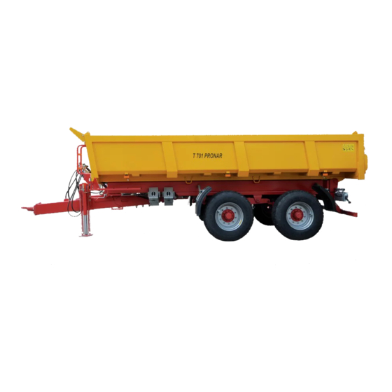
AGRICULTURAL TRAILER
PRONAR T701
TRANSLATION OF THE ORIGINAL DOCUMENT
KEEP FOR FUTURE USE
+48 085 681 64 29
+48 085 681 63 82
+48 085 682 71 10
www.pronar.pl
EN
Advertisement
Table of Contents

Subscribe to Our Youtube Channel
Related Manuals for PRONAR T701


Summary of Contents for PRONAR T701
- Page 1 PRONAR SP. Z O.O. 17- 210 NAREW, UL. MICKIEWICZA 101A, WOJ. PODLASKIE PHONE NO. +48 085 681 63 29 +48 085 681 64 29 +48 085 681 63 81 +48 085 681 63 82 FAX: +48 085 681 63 83 +48 085 682 71 10 www.pronar.pl...
- Page 2 Copyright © PRONAR Sp. z o.o. All rights reserved This study is the property of PRONAR Sp. z o.o. and is a work within the meaning of the Copyright and Related Rights Act. No part of this document may be distributed or copied in any way (electronic, mechanical or other) without the...
- Page 3 Thank you for purchasing our trailer. In the interests of your safety and care for the reliability and durability of the machine, we ask that you familiarise yourself with the content of this manual. Remember!!! Before using the trailer for the first time, check if the wheels are properly tightened!!! Regularly check the technical condition of the machine in accordance with the attached schedule.
- Page 5 INTRODUCTION...
- Page 6 Introduction...
-
Page 7: Introduction
The User Manual is intended for the end user. For this reason, some required maintenance is listed in the inspection tables but the procedure is not described in this publication. To perform the above, call the manufacturer’s authorized service centre. U.10.1.EN PRONAR T701... -
Page 8: Introduction
ADVICE Additional instructions contained in the ADVICE manual describe useful information on the operation of the machine and are marked with a frame with the word ADVICE U.02.1.EN PRONAR T701... -
Page 9: Determination Of Directions In The User Manual
(operator facing the mechanism). direction of travel. Turn left - turn the mechanism coun- Right side - the side on the right hand of ter-clockwise (operator facing the observer facing the machine in the mechanism). forward direction of travel. U.03.1.EN PRONAR T701... -
Page 10: Checking The Trailer After Delivery
• Check the technical condition of the coating. pneumatic hoses. • Visually inspect the trailer’s com- • Make sure there are no hydraulic oil ponents for mechanical damage re- leaks. sulting, e.g., from incorrect machine • Check the trailer’s lighting lamps. U.04.1.EN PRONAR T701... -
Page 11: Start-Up Of The Trailer
If during the test run, alarming symptoms porting the repair. U.12.1.EN PRONAR T701... - Page 12 Introduction...
-
Page 15: Table Of Contents
3.19 3.10 Electrical lighting installation 3.20 RULES OF USE 4.1 Drawbar mounting adjustment 4.2 Connecting and disconnecting of the trailer 4.3 Disconnecting 4.4 Connecting and disconnecting of a second trailer 4.5 Loading and securing of the load 4.10 PRONAR T701... - Page 16 6.2 Parking brake cable replacement 6.3 Adjusting the clearance of the axle bearings 6.4 Brake adjustment 6.5 Assembly and disassembly of extensions 6.6 Consumables 6.11 6.7 Bulbs 6.13 6.8 Faults and how to remove them 6.14 TIRE ASSEMBLY PRONAR T701...
-
Page 17: General Information
GENERAL INFORMATION... - Page 18 General information...
-
Page 19: Trailer Identification
Warranty Card, in the sales The trailer has been marked with a name plate (1) and a serial number (2). Additional documents and in the User Manual. E.3.2.103.01.1.EN PRONAR T701... -
Page 20: Identification Of Driving Axis
622-E.02-1 number of axle, so we recommend that you write these numbers in the manual and have access to Figure 1.2 Axis identification them. (1) Driving axle (2) Nameplate (3) Axle serial number 1.E.3.2.103.02.1.EN PRONAR T701... -
Page 21: Intended Use
• for transporting loads that are unse- the User's Manual and use of the cured or ineffectively secured against T701 trailer, the trailer Warranty card shifting or falling out, and the content of the technical doc- • carry loads that affect uneven loading... - Page 22 124.8 / 91.7 Minimum vertical load capacity of the 3,000 hitch (1) – a different oil may be used, provided it can be mixed with oil in the trailer. Detailed information can be found in the product information card. PRONAR T701...
- Page 23 7 poles in accordance with ISO 1724 Coupling device Type of hitch (1) – a different oil may be used, provided it can be mixed with oil in the trailer. Detailed information can be found in the product information card. E.3.2.103.03.1.EN PRONAR T701...
-
Page 24: Accessories
8mm SUSPENSION (floor) and 6mm (walls) thick. • Tandem suspension on 4 parabolic • Trapezoidal loading springs, with equalizing arms, with 2196mm/2300mm made of ordinary a wheelbase of 1500mm, with rigid quality steel. axles equipped with drum brakes PRONAR T701... - Page 25 • Drawbar support: telescopic with two- matic with manual braking force stage gear. regulator. • Drawbar support: hydraulic straight • The hydraulic braking system. support with cut-off ball valve. • Hydraulic braking system with output • Hydraulic, folding. to the rear. E.3.2.103.04.1.EN PRONAR T701...
-
Page 26: Terms Of Warranty
• from improper operation, adjustment and maintenance, misuse, PRONAR Sp. z o.o. in Narew guarantees • use of a damaged machine, • repairs carried out by unauthorized smooth operation of the machine when it... -
Page 27: Transport
Chocks tained in this manual. The trailer braking or other elements without sharp edges system must be activated and checked should be placed under the trailer wheels PRONAR T701 1.11... - Page 28 If necessary, protect sharp edges maximum design speed. of the trailer, thus securing the securing E.3.1.526.05.1.EN 1.12 PRONAR T701...
-
Page 29: Threat To The Environment
It is pro- an oil waste disposal point. The container hibited to throw or pour oil into the sewage system should be kept away from heat sources, or water reservoirs. flammable materials and food. E.3.1.526.06.1.EN PRONAR T701 1.13... -
Page 30: Withdrawal From Use
During disassembly, use appropriate tools, devices draulic system. (overhead cranes, cranes, hoists, etc.), use per- sonal protective equipment, i.e. protective clothing, In the event of parts being replaced, shoes, gloves, glasses, etc. worn or damaged parts should be taken E.3.1.526.07.1.EN 1.14 PRONAR T701... -
Page 31: Safety Of Use
SAFETY OF USE... -
Page 32: Basic Safety Rules
• Familiarize yourself with the con- • Pronar sp.z o.o. warns of the ex- istence of a residual risk, therefore struction, operation and principles of safe operation of the machine. the application of the principles of safe and wise use should be the •... - Page 33 • Any modification of the trailer pro- not able to operate the trailer, in par- hibited and exempts Pronar from lia- ticular children, intoxicated persons, bility for any damage or injury. persons under the influence of drugs F.3.1.526.01.1.EN...
-
Page 34: Safety During Machine Coupling
• Before coupling the trailer, make sure parking brake. that both machines are technically F.3.1.526.02.1.EN PRONAR T701... -
Page 35: Safety Rules For Operating Hydraulic And Pneumatic Systems
If the oil gets into the eyes, It is forbidden to store hydraulic oil in packaging in- rinse with plenty of water and if irri- tended for food storage. tation occurs, contact a doctor. In the F.3.1.526.03.1.EN PRONAR T701... -
Page 36: Rules Of Safe Technical Service
Manual. • Before starting repair work on hy- trailer, cause damage to the machine and constitute the basis for loss of draulic or pneumatic systems, the residual oil or air pressure must be warranty. PRONAR T701... - Page 37 It (welding, surfacing, straightening, etc.) is prohibited and requires re- is forbidden to work under a trailer raised only with a jack. placement of parts with new ones. • It is forbidden to support the trailer F.3.2.103.04.1.EN PRONAR T701...
-
Page 38: Safe Driving Rules
It is wheel. forbidden to transport loads not al- • Before driving, make sure that the lowed by the manufacturer. machine is correctly connected to the • If possible, avoid driving over uneven PRONAR T701... - Page 39 • Keep bystanders away from the work area. • Use extreme caution when passing 103-F.02-1 near overhead power lines. Figure 2.2 Location of the board • Driving the trailer with open rear flap (1) distinguishing sign doors is prohibited. F.3.2.103.05.1.EN PRONAR T701...
-
Page 40: Loading And Unloading Of A Trailer
CAUTION damage its components. The trailer is not intended for transporting people, animals and hazardous materials. • It is forbidden to stay in the load box during loading and unloading. F.3.2.103.06.1.EN 2.10 PRONAR T701... -
Page 41: Tires
• Check the correct tightening of the increases due to temperature. wheel nuts according to the assumed • Tire valves should be protected with schedule. suitable caps to avoid penetration of • Avoid damaged surfaces, sudden dirt. F.3.1.526.07.1.EN PRONAR T701 2.11... -
Page 42: Description Of Residual Risk
Chapter 2 Safety of use 2.8 DESCRIPTION OF RESIDUAL RISK Pronar Sp z o. o. in Narew made every inspection of the trailer. effort to eliminate the risk of an accident. Residual risk can be reduced to a minimum However, there is some residual risk that... -
Page 43: Information And Warning Stickers
Caution. Before starting work, read the User's Manual. 70RPN-00000004 Wires functions 58RPN-0000041 The place of the transport fastening 58RPN-0000019 Permissible drawbar load of 30 kN 103N-00000002 Caution. Danger of electric shock. 58RPN-0000020 When unloading the trailer keep a safe distance from power lines. PRONAR T701 2.13... - Page 44 The air pressure in the wheels* Switching over the hydraulic circuits of the tipping system of the 1st and 2nd trailer * - The air pressure in the wheels depends on the used tires. F.3.2.103.09.1.EN 2.14 PRONAR T701...
- Page 45 Safety of use Chapter 2 Figure 2.3 Arrangement of information and warning stickers PRONAR T701 2.15...
- Page 46 Chapter 2 Safety of use 2.16 PRONAR T701...
-
Page 47: Construction And Operation
CONSTRUCTION AND OPERATION... -
Page 48: Technical Characteristics
Loading of the drawbar hitch 3000 Min. tractor power KM/kW 124.8/91.7 Telescopic cylinder Stroke 1980 Oil demand Pressure Tipping system 2 cylinders, one-sided tipping ADVICE Depending on the additional equipment of the trailer, some technical parameters may change PRONAR T701... -
Page 49: Overall Dimensions
Construction and operation Chapter 3 3.2 OVERALL DIMENSIONS Figure 3.1 Basic dimensions of the trailer Figure 3.2 Basic dimensions of the trailer - version with extensions G.3.2.103.02.1.EN PRONAR T701... -
Page 50: Chassis
Chapter 3 Construction and operation 3.3 CHASSIS The chassis of the T701 trailer can be a tandem type wheelset - figure (3.3), item made in two versions - with tandem sus- (4)) or boogie type wheelset (figure (3.4), pension - figure (3.1) and with boogie sus- item (4)), and elements of the rear lighting pension - figure (3.2). - Page 51 (3) and spring (figure (3.6)): rotary drawbar eye ø50 (1), plates. ball drawbar K80 (3), rigid rod ø40 (2), The boogie spring suspension consists of or rigid rod ø50 (4)). The drawbar (figure PRONAR T701...
- Page 52 (4), (5) and (6). A hydraulic parking with a straight hydraulic support or a me- stand or a mechanical support is mounted chanical support. to the side of the drawbar. Depending PRONAR T701...
- Page 53 (7) front plate for fastening the tie rod, (8) plate for support fastening, (9) channel section ø40 ø80 ø50 ø50 103-G.05-1 Figure 3.8 Drawbar eyes (1) rotary drawbar eye ø50, (2) drawbar eye ø40, (3) spherical drawbar eye ø80, (4) drawbar eye ø50, G.3.2.103.03.1.EN PRONAR T701...
-
Page 54: Load Box
(3), which serves as a protective element. draulic cylinders. The flap is opened up and down, which allows easy loading and PRONAR, meeting the expectations of unloading. As an additional equipment, the customers, offers the production of a load 103-G.03-1 Figure 3.9... - Page 55 Load box - optional equipment (1) Load box (2) Left leaf (3) Right leaf (4) Left door (5) Right door (6) Rear chute (8) Side step (7) Ladder (8) Side step (9) Rear flap lock (10) Rear flap actuator (11) Lifted flap PRONAR T701...
- Page 56 80 cm high - Fig. 3.9. Extensions the front wall extension is equipped with 103-G.19-1 Figure 3.11 Extensions for the standard box (1) set of extensions (2) side step (3) tilting flap extensions (4) crossbar (brace) extensions (5) extension ladder 3.10 PRONAR T701...
- Page 57 Construction and operation Chapter 3 steps (2) inside and a ladder (5) outside the trailer. The hinged rear flap (3) reaches the hydraulic body of the box and is locked by it during transport. G.3.2.103.04.1.EN PRONAR T701 3.11...
-
Page 58: Service Brake
List of symbols used in the schemes Symbol Description Pneumatic connection, plug Pneumatic connection, socket Drainage valve Main control valve Relay valve Automatic braking force regulator Manual braking force regulator Wire connection Air tank Brake cylinder Control valve (connector) Air filter 3.12 PRONAR T701... - Page 59 103-G.16-1 Figure 3.12 Diagram of the double wire pneumatic system with a manual regulator 103-G.15-1 Figure 3.13 Diagram of the double wire pneumatic system with an automatic regulator 526-G.06-1 Figure 3.14 Diagram of the braking hydraulic system PRONAR T701 3.13...
- Page 60 • A - "Without load” machine's brake (applies only to pneu- • B - „Half-load” matic systems). The three-range braking • C - „Full load”. force regulator used in pneumatic systems G.3.2.103.05.1.EN 3.14 PRONAR T701...
-
Page 61: Parking Brake
Before driving, make sure that Expander arms exerting pressure on the the parking brake is unlocked. brake shoes, causing the axle to become 103-G.04-1 Figure 3.17 Parking brake construction (1) brake mechanism, (2) expander lever, (3) brake cable G.3.2.103.06.1.EN PRONAR T701 3.15... -
Page 62: Hydraulic Tipping System
The lever on this valve can lifting of the load box. be in 2 positions: In the trailer, the system consists of two • [1] - the first trailer's tipping circuit is independent circuits: open 3.16 PRONAR T701... - Page 63 In a trailer equipped with boogie type sus- pension, the system has an additional ADVICE The trailer hydraulic tipping system was circuit [c], used for automatic suspension filled with L-HL32 Lotos hydraulic oil. locking with the use of hydraulic cylinders G.3.2.103.07.1.EN PRONAR T701 3.17...
-
Page 64: Hydraulic System Of The Rear Flap
ADVICE used to open and close the rear flap, the The trailer rear flap hydraulic system was rear flap can be stopped in any position filled with L-HL32 Lotos hydraulic oil. using the tractor's hydraulic distributor G.3.2.103.08.1.EN 3.18 PRONAR T701... -
Page 65: Hydraulic System Of The Straight Support
Figure 3.20 Hydraulic system of the straight ADVICE support (1) straight hydraulic support, (2) plug, The trailer support hydraulic system was (3) cut-off valve, (4) hydraulic conduits, filled with L-HL32 Lotos hydraulic oil. (5) plug socket G.3.2.103.09.1.EN PRONAR T701 3.19... -
Page 66: Electrical Lighting Installation
Arrangement of elements of the electrical installation and signalling reflectors of the trailer is shown in Figure 3.19. 526-G.11-1 Figure 3.21 Connection socket (1) socket(2) beam side view 3.20 PRONAR T701... - Page 67 (2) right rear multifunctional lamp, (3) left rear multifunctional lamp, (4) right rear end-outline lamp, (5) left rear end-outline lamp, (6) license plate lamp, (7) seven-pin socket, (8 ) reflective triangle, (9) white reflective lamp, (10) orange side marker lamp PRONAR T701 3.21...
- Page 68 PP, (PL) - right front position lamp (left); ZP, (ZL) - rear right (left) rear multifunctional lamp; X7P, (GT) front (rear) seven-pin socket ; OTP, (OTL) - right (left) license plate lamp; TOP, (TOL) - right (left) rear end-outline lamp; OBP (OBL) - right (left) side outline lamp G.3.2.103.10.1.EN 3.22 PRONAR T701...
-
Page 69: Rules Of Use
RULES OF USE... - Page 70 Chapter 4...
-
Page 71: Drawbar Mounting Adjustment
Terms of Use Chapter 4 4.1 DRAWBAR MOUNTING ADJUSTMENT The T701 single-shell trailer has an os- drawbar) or the left and right side cillating drawbar, mounted with a pin (3) member of the lower frame, using under the front beam of the lower frame brackets of appropriate height 103-H.02-1... -
Page 72: Connecting And Disconnecting Of The Trailer
If the trailer is equipped trailer is equipped with a support with with an electro-hydraulic brake valve a gear, the height of the drawbar is with electric protection, the cable with adjusted using the gear crank. PRONAR T701... - Page 73 In this case, after starting the tractor and the cultural tractor comply with the requirements of the air compressor, wait until the air in the pneumatic manufacturer of the machine. tank is topped up. PRONAR T701...
- Page 74 Terms of Use • If the trailer is functional, you can machine parking brake. start working. Turn the crank handle an- • Immediately before driving, remove ti-clockwise as far as it will go. the wheel chocks and release the H.3.1.526.03.1.EN PRONAR T701...
-
Page 75: Disconnecting
• Disconnect the electric wire. It is forbidden to disconnect the trailer when the ma- chine is loaded • Disconnect the braking system lines. H.3.2.103.04.1.EN PRONAR T701... -
Page 76: Connecting And Disconnecting Of A Second Trailer
• Immobilize the second trailer with the the tractor cabin and secure it against parking brake. unauthorized access. • Remove the pin from the rear hitch • Disconnecting the hydraulic, pneu- on the first trailer. matic and electric system conduits in PRONAR T701... - Page 77 • Unlock the coupling bolt on the first (4.2). If the automatic rear hitch is used trailer. Remove the bolt and drive the in the trailer, the bolt should be tractor away. H.3.2.103.05.1.EN PRONAR T701...
-
Page 78: Loading And Securing Of The Load
The load must be arranged in such a way that it pay particular attention to the tightness of does not threaten the stability of the trailer and does not hinder driving. the brake cylinders. Loading and driving 4.10 PRONAR T701... - Page 79 Concentrated feed and compound feed: stored chaff 200 - 225 oil cake 880 - 1,000 dried mince 170 - 185 compound feed 450 - 650 mineral mixtures 1,100 - 1,300 oat middlings 380 - 410 wet beet pulp 830 - 1,000 PRONAR T701 4.11...
- Page 80 760 - 800 640 - 760 Other: dry soil 1,300 – 1,400 wet soil 1 900 – 2 100 fresh peat 700 - 850 compost soil 250 - 350 Source: „Technologia prac maszynowych w rolnictwie”, PWN, Warsaw 1985 H.3.2.103.05.1.EN 4.12 PRONAR T701...
-
Page 81: Securing Of The Load
Approximate specific weight of se- accidentally poured material (aggregate). lected materials is presented in table( Regardless of the type of transported load, Therefore, pay special attention not to the user is obliged to secure it in such overload the trailer. H.3.2.103.06.1.EN PRONAR T701 4.13... -
Page 82: Load Transportation
• The tractor operator is required to other road users. equip the trailer with an approved or • The permissible design speed and approved warning reflective triangle. speed resulting from restrictions on • While driving, obey the rules of the 4.14 PRONAR T701... - Page 83 The load must be arranged in such a way that it does not threaten the stability of the trailer and does trailer to overturn as a result of loss not hinder driving. of stability. H.3.2.103.07.1.EN PRONAR T701 4.15...
-
Page 84: Unloading
• the tractor and trailer should be po- raised slowly and smoothly. Rapid lifting of sitioned for driving straight ahead on the load box will cause very high pressure flat and hard ground, on the rear part of the load box as a result 4.16 PRONAR T701... - Page 85 Tilting of the load box may be performed only when trailer's load box fully lowered. the trailer is connected to the tractor When unloading the second trailer, set the H.3.2.103.08.1.EN PRONAR T701 4.17...
-
Page 86: Use Of Tires
• Tire pressure should also be checked cycle. during all-day intensive work. It • Avoid damaged road surfaces, should be taken into account that sudden and variable manoeuvres, an increase in tire temperature can and high speeds when turning. H.3.1.526.09.1.EN 4.18 PRONAR T701... -
Page 87: Technical Inspection Schedule
TECHNICAL INSPECTION SCHEDULE... -
Page 88: General
Repair of the machine during the war- the warranty. ranty period may only be carried out by The trailer's warranty inspection is only Authorized Sales and Service Points carried out by authorized service centres. (APSiO). In the event of unauthorized I.3.1.526.01.1.EN PRONAR T701... -
Page 89: Periodic Inspections Of The Trailer
Inspection carried out for a fee after the first 12 Guarantee APSiO months of use of the trailer, after reporting the owner. Maintenance Service Inspection carried out every 4 years of trailer use (1) - Authorized Sales and Service Centre (2) - post-warranty service PRONAR T701... - Page 90 Parking brake cable tension check • 5.18 • Hydraulic system inspection 5.20 • Pneumatic system inspection 5.21 Lubrication See table: Trailer lubrication schedule 5.22 See table: Tightening schedule for Screw connections inspection 5.27 important bolted connections • Replacement of hydraulic hoses PRONAR T701...
- Page 91 Piston rod stroke in pneumatic and hydraulic sys- 25 - 45 mm tems Minimum brake lining thickness 5 mm With the brake de- Angle between the trailer axis and the fork pressed Parking brake Permitted parking brake cable clearance 20 mm I.3.1.526.02.1.EN PRONAR T701...
-
Page 92: Preparation Of The Trailer
• In case when the wheel needs to be axle shaft bearings. You should be raised during the inspection, place very careful. I.3.2.103.0.1.EN PRONAR T701... -
Page 93: Checking The Air Pressure In The Wheels
The tire air pressure value can be found on the in- a result of delamination of the material. formation sticker attached to the rim. Incorrect tire pressure also causes faster tire wear. I.3.1.526.04.1.EN PRONAR T701... -
Page 94: Measurement Of Air Pressure, Check Tires And Wheels
In the event of especially around the welds and at the mechanical damage, consult your nearest point of contact with the tire. I.3.1.526.09.1.EN PRONAR T701... -
Page 95: Air Tank Drainage
• If the valve stem does not want to 526-I.03-1 return to its position, wait until the tank empties. Then unscrew and clean or Figure 5.4 Air tank (1) drain valve (2) air tank replace the valve with a new one. I.3.1.526.05.1.EN PRONAR T701... -
Page 96: Checking Plugs And Connection Sockets
(e.g. and degree of cleanliness of connections silicone lubricants for rubber elements). and sockets on the agricultural tractor. Each time before connecting If necessary clean or repair tractor sockets. I.3.1.526.06.1.EN 5.10 PRONAR T701... -
Page 97: Covers Inspection
• Check the the completeness of the • Check the completeness of the safety guards. hubcaps. • Check if the covers are properly • If necessary, tighten the the screw mounted, assess the condition of the connections of the covers. fenders. I.3.2.103.08.1.EN PRONAR T701 5.11... -
Page 98: Checking The Trailer Before Driving Off
Driving with malfunctioning lighting or braking sys- clogged ventilation holes. If any tems is prohibited. damage is found, replace the In the event of damage to the trailer, discontinue use until it is repaired. actuator. When mounting the I.3.1.526.08.1.EN 5.12 PRONAR T701... -
Page 99: Cleaning The Air Filters
Installation should spring located in the filter housing. be in reverse order. • Wash the filter element and filter body I.3.1.526.10.1.EN PRONAR T701 5.13... -
Page 100: Checking Brake Lining Wear
• The brake shoes should be replaced Gmin 5mm if the thickness of the brake lining is less than 5 mm. • Inspect the remaining linings for lining wear. 526-I.09-1 Figure 5.9 brake lining thickness inspection (1) blanking plug (2) brake lining I.3.1.526.11.1.EN 5.14 PRONAR T701... -
Page 101: Checking The Clearance Of The Axle Bearings
(e.g. looseness on the spring placed or cleaned and regreased. pins, etc.). When checking bearings, make sure • Check the technical condition of the that any noticeable looseness comes hub cover, replace if necessary. I.3.1.526.12.1.EN PRONAR T701 5.15... -
Page 102: Checking Of Mechanical Brakes
• If the expander arm angle (2) and • Calculate the distance difference. piston rod stroke exceed the range • Check the angle between the cylinder given in table (5.3), the brake should piston axis and the expander lever. be adjusted. I.3.1.526.13.1.EN 5.16 PRONAR T701... -
Page 103: Cleaning The Drainage Valve
• Clean the valve, blow with com- pressed air. • Replace the gasket. • Screw in the valve, fill the tank with 526-I.12-1 air, check the tank for leaks. Figure 5.12 Air tank (1) drain valve (2) tank I.3.1.526.14.1.EN PRONAR T701 5.17... -
Page 104: Checking Of Parking Brake Cable Tension
• Tighten the cable (1) and tighten the • When the mechanism screw is com- nuts (4) of the clamps. pletely removed, the cable should • Apply the parking brake and release hang about 10 to 20 mm. it again. Check (approximately) cable 5.18 PRONAR T701... - Page 105 If it is necessary to change the brake cable, cable should hang about 10- 20 mm. refer to chapter Replacing the parking The axle trailer levers should be in brake cable. I.3.1.526.15.1.EN PRONAR T701 5.19...
-
Page 106: Hydraulic System Checking
If a malfunction has appeared in the brake cylinders, it is forbidden to drive the trailer with a damaged system until the fault is removed. I.3.1.526.16.1.EN 5.20 PRONAR T701... -
Page 107: Pneumatic System Inspection
If there is a leak around the con- nections, tighten the the connector. If air still escapes, replace the joint parts or seal with new ones. I.3.1.526.17.1.EN PRONAR T701 5.21... -
Page 108: Lubrication
Wipe off excess oil. with the lubricant manufacturer's • The replacement of grease in wheel instructions. hub bearings should be entrusted to Table 5.4. Trailer lubrication schedule Name Hub bearings (1) (2 in each hub) 526-I.19-1 5.22 PRONAR T701... - Page 109 Chapter 5 Camshaft sleeves (1) Expander arm 526-I.20-1 Spring leaves (1) Spring sliding surface (2) Spring pin (4) 526-I.22-1 Draw bar hitching eye (1) 103-I.23-1 Control arm pin (1) Draw bar bolt (2) Drawbar leaf spring (3) 103-I.24-1 PRONAR T701 5.23...
- Page 110 Chapter 5 Technical inspection schedule Wheel axle guiding the brake cable 526-I.25-1 Parking brake mechanism 103-I.26-1 Ladder axis 103-I.27-1 Rear hitch 103-I.28-1 5.24 PRONAR T701...
- Page 111 Tipping pin (1) 103-I.29-1 Load box support pin (1) Cylinder mounting socket Tipping cylinder ball joints 103-I.30-1 rear flap wing pivot pins (1) rear flap actuator bearings 103-I.31-1 Slide guide (1) Slide lever (2) Slide rod pins (3) 103-I.32-1 PRONAR T701 5.25...
- Page 112 MoS graphite anti-corrosive spray plain machine oil, silicone spray grease ADVICE Lubrication schedule (Table -Trailer lubrication schedule): D - working day (8 hours of trailer work), M - month I.3.2.103.18.1.EN 5.26 PRONAR T701...
-
Page 113: Screw Connections Inspection
Kolejność dokręcania nakrętek. Wheel nuts must not be tightened with 526-I.28-1 impact wrenches, due to the danger of ex- Figure 5.14 Metric thread screw ceeding the permissible tightening torque, PRONAR T701 5.27... - Page 114 SCREW CONNECTIONS INSPECTION Table 5.7. Schedule for checking the tightness of important bolted connections System / part name Frequency acc. to chap- terDokręcanie Wheel nut (1) kół jezdnych na stronie 5.27 526-I.30-1 Connecting the hitch to the drawbar 103-I.34-1 5.28 PRONAR T701...
- Page 115 Technical inspection schedule Chapter 5 System / part name Frequency Fenders (1) 526-I.34-1 Tank 526-I.36-1 Driving axle (1), (fi xing the driving axle with socket screws) 526-I.37-1 tooltip Front ladder 103-I.38-1 PRONAR T701 5.29...
- Page 116 Chapter 5 Technical inspection schedule System / part name Frequency Control valve (1), brake force regulator (2) 526-I.39-1 Brake cylinder (1) 526-I.40-1 I.3.1.526.19.1.EN 5.30 PRONAR T701...
-
Page 117: Technical Service
TECHNICAL SERVICE... -
Page 118: Wheel Assembly And Disassembly
• Lower the trailer, tighten the nuts ac- • Mount the wheel on the hub, tighten cording to the recommended torque the nuts so that the rim fi ts snugly to and the given order. J.3.1.526.01.1.EN PRONAR T701... -
Page 119: Parking Brake Cable Replacement
• Attach a shackle and bow clamps to The distance between the clamps should be 15mm, one end of the cable. Pay attention with the first clamp placed as close as possible to the thimble. to the correct positioning of the PRONAR T701... - Page 120 Chapter 6 Technical Service cable tension. mechanism and loosen the again. If • Tighten the nuts. necessary, correct the brake cable • Tension the cable with the crank tension. J.3.1.526.02.1.EN PRONAR T701...
-
Page 121: Adjusting The Clearance Of The Axle Bearings
The principle of bearing clearance adjustment (1) hub cap (2) cotter pin (3) nut (4) tapered roller bearing CAUTION Adjustment of bearing clearance may be performed only when the trailer (without load and container) is connected to the tractor. J.3.1.526.03.1.EN PRONAR T701... -
Page 122: Brake Adjustment
(B) the mark on the piston rod in the braked position stroke is not within the correct working (C) arm position in the break release position range, adjust the expander arm. (D) arm in the full brake position • Remember or mark the original PRONAR T701... - Page 123 • If any drum is too hot, correct the cotter pins. brake adjustment and perform the • Turn the adjusting screw (4) clockwise test drive again. to make one or two clicks in the ex- pander arm adjustment mechanism. J.3.1.526.04.1.EN PRONAR T701...
-
Page 124: Assembly And Disassembly Of Extensions
(4) front wall extension 103-J.02-1 Figure 6.7 Installation of the front and side extensions (1) load box (2) front wall extension (3) side extension (4) flap hinge eye (5) side wall extension handle (6) box handle (7) front wall extension handle PRONAR T701... - Page 125 • Screw on the crossbar (4) connecting • Repeat the above steps to install the the side walls (1) and (2); second side wall; PRONAR T701...
- Page 126 Chapter 6 Technical Service • Tighten all bolted connections of the The extensions and the rear flap can be extensions; disassembled after attaching them to the Dismantling should be in the reverse order. lifting slings. J.3.2.103.05.1.EN 6.10 PRONAR T701...
-
Page 127: Consumables
During normal operation of the Table 6.1. Characteristics of oil L-HL 32 Item Name Unit Viscosity classification according to ISO 3448VG Kinematic viscosity at 400C 28.8 – 35.2 Qualitative classification according to ISO 6743/99 Quality classification according to DIN 51502 Flash-point PRONAR T701 6.11... - Page 128 For heavily loaded parts, it is recom- contaminated rags, etc.). The information mended to use lithium grease with the ad- leaflet (product card) should be kept to- dition of molybdenum disulphide (MOS gether with the grease. J.3.1.526.05.1.EN 6.12 PRONAR T701...
-
Page 129: Bulbs
The source of light in the other lamps, not listed in the table, are LEDs and in the event of damage, they are replaced only as a complete lamp, without the possibility of repair or regeneration. J.3.1.526.06.1.EN PRONAR T701 6.13... -
Page 130: Faults And How To Remove Them
Replace brake shoes. Check the oil quality, make sure that the Incorrect hydraulic Incorrect hydraulic oil vis- oils in both machines are of the same system operation cosity grade. If necessary, change the oil in the tractor and/or trailer 6.14 PRONAR T701... - Page 131 Check the slack in the suspension system, Damaged braking system, check the springs. Replace damaged or brake blocking, incorrectly worn parts. Tread wear. adjusted braking system. Check the braking system for malfunc- Too frequent and sudden tions. Adjust the extender levers. braking. PRONAR T701 6.15...
- Page 132 Check braking system. (hardening and Too frequent and sudden Control the braking technique. cracking around braking. Damage arises due to excessive heating the rim), tire crum- Braking system damaged. of the hub and the resulting wheel rims. bling. J.3.1.526.07.1.EN 6.16 PRONAR T701...
-
Page 133: Tire Assembly
TIRE ASSEMBLY... - Page 134 385/65R22,5; 164E ADM991 TL LEAO 11.75x22.5 ET=-30 385/65R22,5; DSR588 DOUBLE STAR 11.75x22.5 ET=-30 385/65R22,5; DSR118 DOUBLE STAR 11.75x22.5 ET=-30 445/65R22,5; DSR118 DOUBLE STAR 14x22.5 ET=0 445/65R22,5 BARUM BS49 16PR MS TL 14x22.5 ET=0 550/60R22,5; 171A8 TR08 16PR TL MIT 16x22,5 ET=0 PRONAR T701...
- Page 135 700/50-26,5; 16PR 174A8 FL 648 BKT 24x26,5 ET=-50 600/55-22,5; 16PR Float.648 TL BKT 20x22,5 ET=-40 710/45-26,5; 169A8 T404 Trelleborg 24x26,5 ET=-50 425/65R22,5; Bandenmarkt zz 168F TL 13x22,5 ET=0 425/65R22,5; WPM 80km/h De Molen 13x22,5 ET=0 425/65R22,5; BARUM B44T TL 13x22,5 ET=0 PRONAR T701...
- Page 136 Chapter 7 Tire assembly PRONAR T701...
Need help?
Do you have a question about the T701 and is the answer not in the manual?
Questions and answers