
Related Manuals for Teknik Barrister 5420330


Summary of Contents for Teknik Barrister 5420330
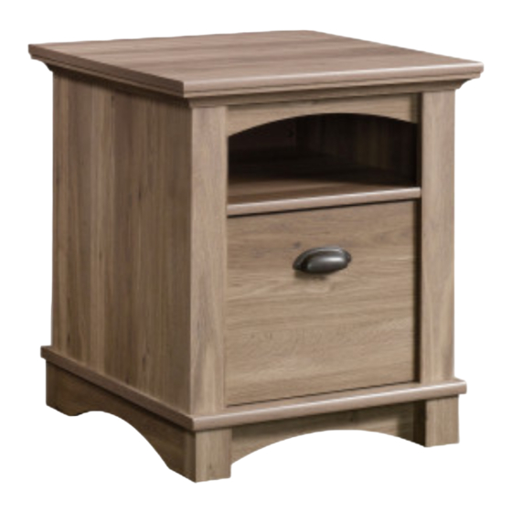
- Page 1 Teknik www.teknikoffice.co.uk Gets on your couch’ s good side. Barrister Home Side Table Model 5420330 NOTE: THIS INSTRUCTION BOOKLET CONTAINS IMPORTANT SAFETY INFORMATION. PLEASE READ AND KEEP FOR FUTURE REFERENCE.
- Page 2 Table of Contents Assembly Tools Required Part Identifi cation No. 2 Phillips Screwdriver Tip Shown Actual Size Hardware Identifi cation Assembly Steps 5-23 Hammer Not actual size Skip the power trip. This time. Page 2...
- Page 3 Now you know Part Identifi cation our ABCs. å While not all parts are labeled, some of the parts will have a label or an inked letter on the edge to help distinguish similar parts from each other. Use this part identifi cation to help identify similar parts. RIGHT END (1) LEFT END (1) TOP (1)
- Page 4 Hardware Identifi cation å Screws are shown actual size. You may receive extra hardware with your unit. 35AA UNIVERSAL CABINET RAIL - 2 35AC DRAWER RIGHT - 1 35AD DRAWER LEFT - 1 MOLDING 10A SLIDE CAM - 2 HIDDEN CAM - 8 CAM DOWEL - 8 CONNECTOR - 4 CORNER BRACKET - 4...
- Page 5 Step 1 Assemble your unit on a carpeted fl oor or on the empty å carton to avoid scratching your unit or the fl oor. Push eight HIDDEN CAMS (1F) into the ENDS (A and B) å and SHELF (E). Then, insert the metal end of a CAM DOWEL (2F) into each HIDDEN CAM.
- Page 6 Step 2 Tap four MOLDING CONNECTORS (17F) into the notches å in the TOP MOLDINGS (K and L). Use your hammer to tap the MOLDING CONNECTORS (17F) into the notches in the TOP MOLDINGS. Flat end Unfi nished surface Flat end Flat end Unfi...
- Page 7 Step 3 Carefully turn the assembled TOP MOLDINGS (K and L) over. å Remember: Fasten the TOP MOLDINGS (K and L) to the TOP (C). Use å Righty tighty. eight BROWN 1-5/8" FLAT HEAD SCREWS (55S). Lefty loosey. NOTE: Do not overtighten the SCREWS into the TOP. å...
- Page 8 Step 4 Slide the END MOLDINGS (M) onto the notched edges of å the ENDS (A and B). *U.S. Patent No. 5,499,886 å Slide the END MOLDING (M) Notched edge onto the notched edge. Notched edge Groove Groove Page 8...
- Page 9 Step 5 Place the BACK (F) on edge on the LEFT END (B) å against the END MOLDING (M). Fasten the SHELF (E) to the LEFT END (B). Tighten å two HIDDEN CAMS. i t h f a c S u r D E N H I D Notch...
- Page 10 Step 6 Fasten the RIGHT END (A) to the SHELF (E). Tighten two å HIDDEN CAMS. Maximum Arrow 210 degrees NOTE: Be sure to center the BACK (F) evenly between the å ends of the END MOLDINGS (M). Minimum 190 degrees Edge with CAM DOWELS The edge of the BACK (F)
- Page 11 Step 7 Carefully turn your unit onto the BACK (F) and END MOLDINGS (M). å Fasten the BACK (F) to the END MOLDINGS (M). Use ten BLACK 9/16" å LARGE HEAD SCREWS (1S). NOTE: There are no pre-drilled holes in the END MOLDINGS (M). The å...
- Page 12 Step 8 Fasten the ENDS (A and B) to the SIDE TOP å MOLDINGS (K). Tighten four HIDDEN CAMS. Maximum Arrow 210 degrees Minimum 190 degrees Page 12...
- Page 13 Step 9 Fasten the EXTENSION BRACKETS (45G) to the å ENDS (A and B). Use eight BLACK 9/16" LARGE Now might be a HEAD SCREWS (1S). good time to refresh your drink. BLACK 9/16" LARGE HEAD SCREW (8 used in this step) Page 13...
- Page 14 Step 10 Fasten the UNIVERSAL CABINET RAILS* (35AA) to the å EXTENSION BRACKETS (45G) in the exact holes shown. Use four GOLD 5/16" FLAT HEAD SCREWS (3S). *patent pending glide system å GOLD 5/16" FLAT HEAD SCREW (4 used in this step) Glide end Page 14...
- Page 15 Step 11 Fasten the BOTTOM (D) to the ENDS (A and B). Use four å BLACK 1-15/16" FLAT HEAD SCREWS (113S). 113S BLACK 1-15/16" FLAT HEAD SCREW (4 used in this step) Flat edge Rounded edge Page 15...
- Page 16 Step 12 Fasten the BASES (G) to the PLINTHS (P). Use eight å SILVER 1-1/8" FLAT HEAD SCREWS (10S). SILVER 1-1/8" FLAT HEAD SCREW (8 used in this step) Page 16...
- Page 17 Step 13 Fasten the CORNER BRACKETS (31G) to the BOTTOM (D). å Use eight BLACK 9/16" LARGE HEAD SCREWS (1S). BLACK 9/16" LARGE HEAD SCREW (8 used in this step) Page 17...
- Page 18 Step 14 Fasten the BASES (G) to the CORNER BRACKETS (31G). å Use eight BLACK 9/16" LARGE HEAD SCREWS (1S). BLACK 9/16" LARGE HEAD SCREW (8 used in this step) Curved edge Curved edge Page 18...
- Page 19 Step 15 Fasten the SIDE BASES (H) to the CORNER BRACKETS (31G). å Use eight BLACK 9/16" LARGE HEAD SCREWS (1S). Don't worry. It isn't Rome. This can be built NOTE: You may need to loosen the SCREWS in the CORNER å...
- Page 20 Step 16 The tabs should insert freely With the palm of your hand, into the slots. Gently tilt the tap the DRAWER BOTTOM DRAWER SIDES side to side down into the groove. until the tabs slip into the slots. fi n i s h r f a D706...
- Page 21 Step 17 Insert a SLIDE CAM (10A) into the DRAWER SIDES (D22 and D23). å Fasten a DRAWER RIGHT (35AC) to the DRAWER RIGHT SIDE (D22) and a DRAWER LEFT (35AD) to the DRAWER LEFT å SIDE (D23). Use four GOLD 5/16" FLAT HEAD SCREWS (3S) through holes #1 and #2. NOTE: The screw head in the CAM must be visible through the slotted hole in the SLIDE.
- Page 22 Step 18 Carefully stand your unit upright. å To insert the drawer into your unit, tip the front of the å drawer down and drop the glides on the drawer behind the glides on the unit. Lift the front of the drawer up and slide it into the unit.
- Page 23 Step 19 To make adjustments to the drawer, loosen SCREW #2 in the SLIDES a 1/4 turn, then turn the CAM clockwise or å counter-clockwise. Notice how the drawer raises or lowers as you turn the CAM. The higher the screw in the oblong hole, the higher your drawer front will be.
- Page 24 WARNING Please use your furniture correctly and safely. Improper use can cause safety hazards, or damage to your furniture or household items. Carefully read the following chart. Look out for: What can happen: How to avoid the problem: • Overloaded drawers and shelves. •...
Need help?
Do you have a question about the Barrister 5420330 and is the answer not in the manual?
Questions and answers