
Related Manuals for Teknik 5420649


Summary of Contents for Teknik 5420649
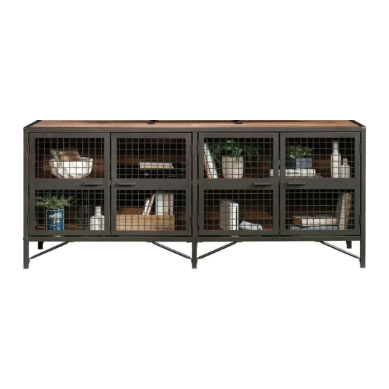
- Page 1 Teknik www.teknikoffice.co.uk It stands. You sit. A thing of beauty, this one. Industrial Styled Sideboard Boulevard Cafe Collection | Model 5420649...
- Page 2 Table of Contents Assembly Tools Required Part Identifi cation No. 2 Phillips Screwdriver Tip Shown Actual Size Hardware Identifi cation Assembly Steps 5-20 Français 21-24 Skip the power trip. This time. Español 25-28 Safety 29-30 Warranty WARNING Use of a TV that is too heavy or large is hazardous. A TV that is too heavy will create a risk of a tip-over that can cause severe injury or death.
- Page 3 Now you know Part Identifi cation our ABCs. å While not all parts are labeled, some of the parts will have a label or an inked letter on the edge to help distinguish similar parts from each other. Use this part identifi cation to help identify similar parts. RIGHT END (1) BACK (1) FOOT (2)
- Page 4 Hardware Identifi cation å Screws are shown actual size. You may receive extra hardware with your unit. LARGE CAM SMALL CAM WOOD HIDDEN CAM - 6 SCREW - 2 SCREW - 4 DOWEL - 4 GROMMET APPLIQUE CARD - 1 METAL PIN - 8 RUBBER SLEEVE - 8 WITH CAP - 2...
- Page 5 Step 1 Assemble your unit on a carpeted fl oor or on the empty å carton to avoid scratching your unit or the fl oor. Fasten the TOP TUBES (E and F) to the TOP (D). Use å twelve BLACK 1/2" PAN HEAD SCREWS (17). These edges must be even.
- Page 6 Step 2 Fasten two MAGNETIC CATCHES (10) to the TOP (D). å Use four BLACK 5/8" PAN HEAD SCREWS (14). Turn two LARGE CAM SCREWS (2) into the TOP (D). å Turn four SMALL CAM SCREWS (3) into the REAR TOP å...
- Page 7 Step 3 Push six HIDDEN CAMS (1) into the BACK (G) å and UPRIGHT (C). Some assembly Insert two GROMMETS WITH CAPS (6) into the BACK (G). å (and snacks) required. Arrow Arrow Hole The arrow in the HIDDEN CAM must point toward the hole in the edge of the board.
- Page 8 Step 4 Fasten the BACK (G) to the TOP REAR TUBE (E). Tighten å four HIDDEN CAMS. S u r f a c H I D D E N i t h Page 8...
- Page 9 Step 5 Fasten the UPRIGHT TUBE (I) to the UPRIGHT (C). Use å four BLACK 1/2" PAN HEAD SCREWS (17). NOTE: Two screws will turn into each surface of the å UPRIGHT (C). Be sure to use the exact holes shown. BLACK 1/2"...
- Page 10 Step 6 Push two WOOD DOWELS (4) into the TOP (D). å Fasten the UPRIGHT (C) to the TOP (D). Tighten two å HIDDEN CAMS. NOTE: Be sure the WOOD DOWELS in the TOP insert å into the holes in the UPRIGHT. i t h f a c S u r...
- Page 11 Step 7 Fasten the BOTTOM TUBES (J and L) to the BOTTOM (K). å Use twelve BLACK 1/2" PAN HEAD SCREWS (17). Now might be a good time to refresh your drink. BLACK 1/2" FLAT HEAD SCREW These edges must be even. (12 used in this step) Edge with more holes The TUBE should cover...
- Page 12 Step 8 Flip the BOTTOM (K) over. å Push two WOOD DOWELS (4) into the BOTTOM (K). å Fasten two MAGNETIC CATCHES (10) to the BOTTOM (K). å Use four BLACK 5/8" PAN HEAD SCREWS (14). BLACK 5/8" PAN HEAD SCREW (4 used for the MAGNETIC CATHCHES) Page 12...
- Page 13 Step 9 Flip the BOTTOM (K) over and fasten it to the BACK (G) and å UPRIGHT (C). Use six BLACK 2-1/4" PAN HEAD SCREWS (12). NOTE: Be sure the WOOD DOWELS in the BOTTOM insert å into the holes in the UPRIGHT. BLACK 2-1/4""...
- Page 14 Step 10 Fasten the ENDS (A and B) to the ends of the TUBES (E, F, J, å and L). Tighten eight BLACK 1-3/8" HEX HEAD SCREWS (13) using the L-WRENCH (9). BLACK 1-3/8" ALLEN HEAD SCREW (8 used in this step) BLACK 1-3/8"...
- Page 15 Step 11 Fasten the FEET (M) to the BOTTOM TUBES (J and L). å Tighten four BLACK 1/2" HEX HEAD SCREWS (15) using the L-WRENCH (9). BLACK 1/2" FLAT HEAD SCREW (4 used in this step) Page 15...
- Page 16 Step 12 Fasten four FOOT BRACES (N) to the FEET (M) and å BOTTOM TUBES (J and L). Tighten eight BLACK 1/2" HEX HEAD SCREWS (15) with the L-WRENCH (9). Fasten the remaining four FOOT BRACES (N) to the å ENDS (A and B) and BOTTOM TUBES (J and L).
- Page 17 Step 13 Carefully stand your unit upright. å Pro Tip: Lift with your Push the RUBBER SLEEVES (8) over the METAL å legs. And, you know, PINS (7). Insert the METAL PINS into the hole locations of your arms. your choice in the ENDS (A and B) and UPRIGHT (C). Set the ADJUSTABLE SHELVES (H) onto the METAL PINS.
- Page 18 Step 14 Fasten the RIGHT DOORS (P) to the RIGHT END (A) and å UPRIGHT (C). Use eight BLACK 1/2" MACHINE SCREWS (16). BLACK 1/2" MACHINE SCREW (8 used in this step) Page 18...
- Page 19 Step 15 Fasten the LEFT DOORS (O) to the LEFT END (B) and å UPRIGHT (C). Use eight BLACK 1/2" MACHINE SCREWS (16). To vertically adjust the DOORS (O and P), loosen the screws in å the hinges and make adjustments. Then, tighten the screws. BLACK 1/2"...
- Page 20 Step 16 Peel APPLIQUES from the APPLIQUE CARD (5) and stick them onto each visible HIDDEN CAM. å Apply the WARNING LABEL (11) to the TOP (D). You should be able to read the label when the TV is removed å...
- Page 21 WARNING Please use your furniture correctly and safely. Improper use can cause safety hazards, or damage to your furniture or household items. Carefully read the following safety information. Death or serious injury may occur when children climb on audio and/or video equipment furniture. A remote control or toys placed on the furnishing may encourage a child to climb on the furnishing and as a result may tip over onto the child.
Need help?
Do you have a question about the 5420649 and is the answer not in the manual?
Questions and answers