Table of Contents
Advertisement
Quick Links
Advertisement
Table of Contents

Related Manuals for Vista Onvif VIP2 VK2-720VZMX


Summary of Contents for Vista Onvif VIP2 VK2-720VZMX
- Page 1 VK2-720VZMX Configuration and User manual...
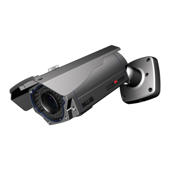
- Page 2 DESCRIPTION ------------------------------------------------------------------------------------------------------------------------------------- The VK2-720VZMX external 18:1 zoom module with integrated IR illumination, is an internet protocol based megapixel network camera with a built-in web based viewer on Internet Explorer®. The camera has a connection feature for third-party applications and compatible with supplied Utility software for easy installation and Client software to search, configure, manage, live view, record and playback.
-
Page 3: Installation
INSTALLATION ------------------------------------------------------------------------------------------------------------------------------------- Carefully remove the contents from the box, and verity that nothing was damaged during shipping. Figure 1 Parts Name... -
Page 4: Before Installation
Before Installation Before installing the camera, thoroughly familiarise yourself with the information in this section of the manual. - To ensure secure access to the IP camera, place the camera behind a firewall when it is connected to a network. Starting Installation Installation1 (Cable through the wall ) Figure 2 Installation 1... - Page 5 Installation 2 (Using the conduit knockout on the camera mounting base) A. Drill the mounting location, using the template sheet supplied. B. Insert the plastic anchors into the drilled holes. Figure 3 Installation 2 C. Connect RJ45 cable and other required connections. D.
- Page 6 Connection Cable [Connection Cable] Main POWER connection - RED; DC12V or AC24V - WHITE; GND or AC24V Heater POWER connection (Optional) - ORANGE; DC12V or AC24V - BLACK; GND or AC24V ALARM connection - PINK; Alarm Input 1 - GREEN; GND - YELLOW;...
- Page 7 Connection to an IP network A standard straight network patch cable can be used to connect the camera to a switch or hub. Generally if connecting directly to a PC a crossover cable would be used. IP Assignment When a camera is first connected to the network it has no IP address. To allocate an IP address to the device use the “Smart Manager”...
- Page 8 Click OK, the devices IP address will be changed, ensure the PC is on the same network, to gain connection. The connection status of each device on the network is indicated by the following icons: : Available for connection to the camera : Loading settings information of video after connecting the camera.
-
Page 9: Operation
The minimum system requirements to use a Web browser with this IP camera are as follows: - CPU: Pentium® 4 microprocessor, 2.0GHz - Operational System: Windows XP® or Windows Vista® or Windows7® - System Memory: RAM 512 Mbyte - Ethernet: 100 Mbit - Video Resolution: 1024(Horizontal) x 768(Vertical) pixels or higher - Internet Explorer®... - Page 10 - Click the Live View icon for default live image view or the Setup icon to change the configuration values. Main Menu [Main menu] The dialog box will be appears. admin - Type User ID and Password in the dialog box. The default User ID and Password is NOTE For security purposes, be sure to change the password after you log on for the first time.
-
Page 11: Live View
LIVE VIEW ------------------------------------------------------------------------------------------------------------------------------------- The Live View page provides you to select the properties of video source. You can view the live image from this page and also access the Setup menu and operate the main functions. [Main Live View Page] Live Video Page Icons Hide Main Icons: Hides main icons in the live view page. - Page 12 Source: Specify the viewable video stream source to display in live view page. View Size: Specify the viewable video size to display in live view page. Stream Type: Specify the internet protocol to display in live view page. ROI View: Specify the specially selected area to transfer using different stream feature in the primary video image.
-
Page 13: Upgrading The Firmware
Troubleshooting ------------------------------------------------------------------------------------------------------------------------- If you suspect a problem is being caused by incorrect configuration or some other minor problem, consult the troubleshooting guide below. Upgrading the Firmware Firmware is software that determines the functionality of the network camera. One of your first actions when troubleshooting a problem should be to check the current firmware. - Page 14 Check the Video & Image setting. 8. Blurred images. Refocus the camera. 9. Poor image quality. Increased lighting can often improve image quality. Check that there is sufficient lighting at the monitored location. Check all image and lighting settings. 10. Rolling dark bands or flickering in image. Try adjusting the Exposure Control setting under AE and AWB part.
Need help?
Do you have a question about the Onvif VIP2 VK2-720VZMX and is the answer not in the manual?
Questions and answers