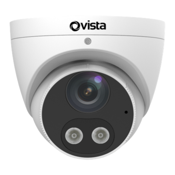
Vista VIP Series Quick Manual
Ip eyeball, fixed dome & fisheye
Hide thumbs
Also See for VIP Series:
- Quick manual (16 pages) ,
- Manual (16 pages) ,
- Quick manual (19 pages)
Summary of Contents for Vista VIP Series
- Page 1 IP Eyeball, Fixed Dome & Fisheye VIP Series Eyeball, Fixed Dome & 360 Range Quick Guide Ver 1.4 2023-01-19...
-
Page 2: Before You Begin
CCTV, IT and electrical wiring and products. Technical Support If you still have questions after referring to the guide, or require more information, please contact Vista Technical Support or use the QR code. Vista Technical Support - +44 (0) 118 912 5125... -
Page 3: Packing List
Packing List Please contact Norbain if any items are missing or damaged and note contents will vary according to each camera model number. ➢ Camera ➢ Waterproofing items* ➢ Fixing Screws* ➢ Template* ➢ This guide Including waterproofing components such as tape and sealing grommets. Fixing screws and\or hex key according to camera model and requirement Drilling template Safety &... - Page 4 Drilling and Mounting - All Cameras Common to all cameras is the template and drilling procedure. 1. Hold supplied template to ceiling or wall and drill 6mm to 6.5mm diameter holes to 30-mm depth. 2. Drill hole for fly lead cable to pass through (1) 3.
- Page 5 1. Loosen lock screw on camera and remove housing by turning to the position (1) shown below. 2. Connect cables and secure camera base to the wall\ceiling 3. Align housing as shown below-right to engage it correctly, then rotate clock/counter clockwise at least 8 degrees to lock it. Connect cable and protect it with waterproof tape (Optional) insert a...
- Page 6 VIP-T5MP28IRM, VIP-T5MP40IRM VIP-T5MP28IRWLM, VIP-T5MP40IRWLM VIP-T8MP28IRWLM, VIP-T8MP28IRM, VIP-T8MP40IRWLM Appearance and cable identification may vary between each model. Type A Type B 1. Camera base 2. Housing 3. Mic* 4. Lens 5. Power interface(12 VDC) 6. Ethernet interface 7. (Optional) Alarm* 8. (Optional) Audio* *Not included for VIP-T5MP28IRM, VIP-T5MP40IRM (Optional) Insert Micro SD Card For cameras supporting Micro SD, insert card after...
- Page 7 Type A Type B 1.Loosen locking screw and 1. Remove housing from base by remove housing by turning to aligning marks (below). position shown below (1). Install mark Install mark 2. Connect cables and screw 2. Connect cables and screw camera base to wall\ceiling.
- Page 8 VIP-D2MP27V135IRVRMAUAL VIP-D5MP27V135IRVRMAUAL VIP-D8MP28V12IRVRMAUAL Appearance and cable identification may vary between each model. Transparent dome cover Safety wire Reset button Micro SD card slot 1. Audio input/output/GND 2. Alarm input (IN,GND) Alarm output(N,P) 3. Power interface 4. Ethernet interface (Optional) Insert Micro SD Card Insert SD card into slot for local storage function.
- Page 9 1. Fix camera to wall\ceiling and connect all cables required (right). 2. Adjust position and elevation of camera for the required coverage - tighten screws (below). Lens base Rotate the lens base horizontally. Fastening screw Loosen the fastening screws and rotate the lens vertically.
- Page 10 VIP-D2MP28IRVRAUAL VIP-D5MP28IRVRAUAL 79.4mm (3.1'') Audio input (Sound pickup) Audio output (Outdoor sound box) Network Alarm Alarm input output Network access (Voice (Alarm device activated indicator) Power connected switch) adapter through copper interface 1.Audio\Mic In 2.Audio Out 3.Alarm In 4.Alarm Out 5.Power (12 VDC) 6.Ethernet interface (Optional) Insert Micro SD...
- Page 11 2. Rotate camera to position required via lens base (1). Referring to image (right), loosen Lens locking screw (2) and base adjust elevation to obtain the coverage Fastening required. Once screw finished, tighten locking screw (2). 3.Attach the shroud and lock it into buckle on base of camera (left).
- Page 12 VIP-F5MP14IRMAUAL Fisheye 108mm 125mm (4.25") (4.7") Display device Alarm output Audio input (Alarm indicator) (Sound pickup) Alarm input (Voice activated switch) Power adapter IP Network Audio output 1.Analogue Display 2.Audio Input 3. Alarm In 4.Power (12 VDC) 5.Audio out 6. Ethernet 7.Alarm out 1.Refer right and remove hosing from camera...
- Page 13 Note: Insert SD card into slot for local storage function. Hot plugging is not recommended. Power off first! 2. Fix camera to wall\ceiling, pass through cables and connect as required. 3. Reattach outer housing ring by using the reverse procedure as you followed when removing it - twist in opposite direction to close.
- Page 14 1. Either open Web browser on laptop and enter the camera's IP address in the address bar, press Enter. 2. Or use the QR code provided to download the Vizion Discovery IP camera discover tool onto the Laptop. 3. Follow on-screen instructions to permit and instal any required plug-in.
- Page 15 Power Requirements per Camera Model CAMERA MODEL PSU Minimum 802.3af VIP-D2MP27V135IRVRMAUAL 7.5W 12VDC @ 1Amp VIP-D2MP28IRVRAUAL 5.0W 12VDC @ 1Amp VIP-D5MP27V135IRVRMAUAL 7.0W 12VDC @ 1Amp VIP-D5MP28IRVRAUAL 4.5W 12VDC @ 1Amp VIP-D8MP28V12IRVRMAUAL 9.0W 12VDC @ 1Amp VIP-F5MP14IRMAUAL 8.5W 12VDC @ 1Amp VIP-T5MP27V135IRM 7.0W 12VDC @ 1Amp...
- Page 16 This is a Class A product. In a domestic environment this product may cause radio interference in which case the user may be required to take adequate measures. No liability will be accepted by Vista for any errors or omissions in this information and reserves the right to make changes to the product and...


Need help?
Do you have a question about the VIP Series and is the answer not in the manual?
Questions and answers