Table of Contents
Advertisement
Quick Links
Advertisement
Table of Contents

Related Manuals for Vista VA Series


Summary of Contents for Vista VA Series
- Page 1 Analogue Camera Range VA Analogue Series Camera Range Quick Guide Ver 1.0 2023-09...
-
Page 2: Before You Begin
CCTV, IT and electrical wiring and products. Technical Support If you still have questions after referring to the guide, or require more information, please contact Vista Technical Support or use the QR code. Vista Technical Support +44 (0) 118 912 5125... -
Page 3: Safety And Maintenance Instructions
Safety and Maintenance Instructions • Use only correctly rated PSU meeting requirements shown in section 5. titled Power Requirements Per Camera Model • Keep lens cover in place until installation completed - prevent damage. • Ensure power cable lengths are within specification for correct operation to avoid power loss and excessive voltage drop. - Page 4 Once powered up, unscrew weatherproof cover and press & hold button for 5-seconds to change video format to the next in the sequence; AHD, CVI, CBVS, TVT. Repeat until required video format is selected and you can view your camera image correctly. Refit the weatherproof cap.
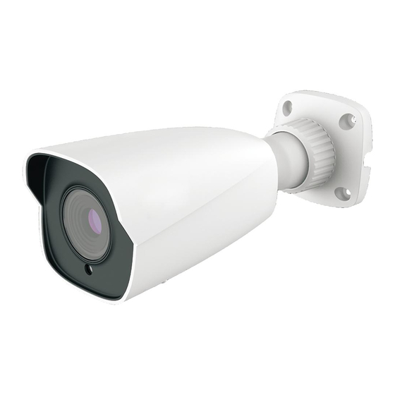
- Page 5 BULLET CAMERAS VA-B5MP28V12IR, VA-B2MP28V12IR Referring to the image of your camera below - drill screw holes according to the camera base or supplied template. Drill hole for cable then route the cable and connect. Secure mounting base of camera to the wall with screws as shown.
-
Page 6: Dome Cameras
DOME CAMERAS VA-D5MP28V12IRVR, VA-D2MP28V12IRVR Drill screw holes according to the holes of the mounting base of the camera, or template if supplied, as well as the cameras cable. Remove the lower dome of the camera by removing the screws (lower left image). If screws are not visible, then your camera has a trim ring that needs to be removed first –... - Page 7 Connect the video and power cables. Preview the image of the camera on a monitor and adjust the camera as required via the three-axis adjustment (below). Re-fit the domes bubble to the camera using the reverse of the procedure you followed in step 2 – remembering to refit the trim ring if one was included.
- Page 8 TURRET CAMERAS VA-T5MP28V12IR, VA-T2MP28V12IR Drill screw holes according to the holes of the mounting base of the camera, or template if supplied, as well as for the cables. Remove the mounting base of the camera – noting there are two possible removal methods: either via lock screw or simple twist and aligning of marks (below).
-
Page 9: Box Camera
Box Camera VA-X2MP Fixing of the box camera is entirely dependent upon your chosen box camera bracket or housing. The below example acts as a basic guide only and you must use instructions supplied with your chosen bracket or housing. Attach your chosen CS lens to the box camera body and connect the P-... - Page 10 Focus and zoom the lens according to the lens manufacturer’s instructions. Continue to the next section, 4. Power-up and Focus/Zoom Camera, for details of gaining access to the cameras OS menu via the Vista VA-DVR to make any other required changes.
- Page 11 Follow the below to connect the camera to your Vista VA-DVR and to use PTZ features to remotely zoom and focus your camera to complete the installation.
- Page 12 Highlight the camera in the Live view and click the PTZ icon on the quick menu bar (right). From the displayed pop-up menu, click the below Coaxial Control menu option. Referring to the Control PTZ tab and panel (right), simply click the zoom, focus and iris controls to adjust the camera for the required...
- Page 13 10. While still in the Control PTZ dialogue box (previous example), simply click the TAB to the right titled OSD Menu Control (below right). Use the resulting on-screen virtual joystick to navigate the camera menus - use the virtual button to enter the currently selected menu or change to the option currently highlighted.
- Page 14 Power Requirements Per Camera Model CAMERA MODEL PSU Minimum VA-B5MP28V12IR 12VDC @ 1Amp VA-B2MP28V12IR 12VDC @ 1Amp VA-D5MP28V12IRVR 12VDC @ 1Amp VA-D2MP28V12IRVR 12VDC @ 1Amp VA-T5MP28V12IR 12VDC @ 1Amp VA-T2MP28V12IR 12VDC @ 1Amp VA-X2MPIR 12VDC @ 1Amp...
- Page 15 This is a Class A product. In a domestic environment this product may cause radio interference in which case the user may be required to take adequate measures. No liability will be accepted by Vista for any errors or omissions in this information and reserves the right to make changes to the product and...
Need help?
Do you have a question about the VA Series and is the answer not in the manual?
Questions and answers