Table of Contents
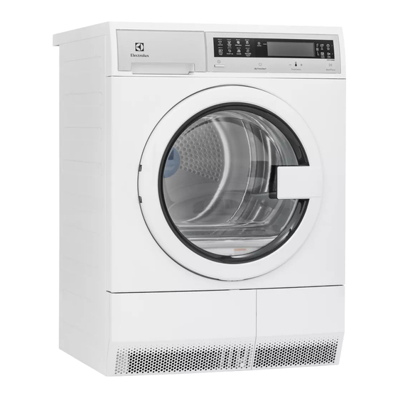
Advertisement
Advertisement
Table of Contents

Related Manuals for Electrolux EID200QSW00


Summary of Contents for Electrolux EID200QSW00
- Page 1 Technical Service Manual Urban Living Dryer-EID200QSW00 Publication # May 2016...
-
Page 3: Table Of Contents
Table of Contents 1. Purpose of this Manual.................4 0X32: Conductimetric Sensor Frequency Too Low....45 2. Safety Information...................5 0X45: Door Closed Sensing Error..........46 3. Warnings.......................8 0X55: FCV Safety Error ..............46 4. Product Features..................9 0X56: FCV Motor Plug Not Connected ........47 5. -
Page 4: Purpose Of This Manual
1. Purpose of this Manual The purpose of this Manual is to provide information regarding repair procedures of Dryer fitted with the Electro- Mechanical Control System. This Manual is intended for the use of Service Engineers of Electrolux. The Manual includes the following topics: •... -
Page 5: Safety Information
2. Safety Information Read the entire Manual before attempting to service this product. Pay attention to all Warnings, Cautions, Notes and Important Information. Failure to do so could result in serious personal injury and / or equipment damage. DEFINITIONS WARNING Indicates a hazardous situation which, if not avoided, could result in serious injury or death. - Page 6 Safety Information 208-240 V Electric Dryer 10-30 R 14-30 R UL-Approved Service Cord must be 3-Wire 4-Wire installed on Electric Dryers (not provided with unit except those manufactured (Fused 30 Amp) (Fused 30 Amp) for sale in Canada). Avoid Fire Hazard or Electrical Shock. Do not use an Adapter Plug or Extension Cord or remove Grounding Prong from the Electrical Power Cord.
- Page 7 Safety Information Protect Children recommended in the Owner’s Guide. Use only authorized factory parts. • Do not allow children to play on or in the Dryer. Close supervision of children is necessary when • Do not tamper with controls. the Dryer is in use. As the children grow, teach •...
-
Page 8: Warnings
3. Warnings • Any work on Electrical Appliances must be carried out by qualified professional only. • Confirm that the Power System is operational before working on the Appliance. • Check that the Appliance is restored to its original safety condition after the operation is complete. Take the plug out of the socket to disconnect the power supply before you access internal components. -
Page 9: Product Features
4. Product Features LED Display Water Container Control Lock Drum Light Door Latch Reversible Door Moisture Sensor Condenser Access Door Striker Door Lint Filter Adjustable Leveling Leg Condenser Access Door Latch Drying Rack* Fig. 2: Product Features * Not all models come with a drying rack and stacking kit from the factory. They may be purchased as accessories. -
Page 10: Model Specifications
5. Model Specifications DESCRIPTION EIED200QSW00 Capacity D.O.E. 4.0 Cu. Ft. Features Pull-to-Open Door IQ-Touch™ Electronic Controls Dry System Condensing LED Lighting Tumble System Reversing Moisture Sensor Dryer Drum Stainless Steel Reversible Door Adjustable Leveling Legs Cycles Normal, Heavy Duty, Delicates, Casual, Mixed 7 Dry Load,Touch Up, Towels Jeans, Fast Dry, Wool, Timed Dry... - Page 11 Model Specifications DESCRIPTION EIED200QSW00 Specifications Color Silver White Power Supply Connection Location Right Top Rear Voltage Rating 208 / 240 V AC Connected Load (KW Rating) @ 208 / 240 Volts 2800 W Amps @ 208 / 240 Volts Heating Element @ 208 / 240 Volts (Watts) 1,200 Shipping Weight (Approx.) 125 Lbs.
-
Page 12: Tools And Equipments
6. Tools and Equipments Fig. 3: Tools and Equipments... -
Page 13: Electrical Characteristics
7. Electrical Characteristics 7.1 Main Control The Main Control is made up of the following components: User Interface (UI) Board 2. Main Control Board 7.1.1 User Interface (UI) Board The User Interface (UI) board contains the selector buttons to adjust temperature (high, normal, low and air dry) and options (chime, wrinkle, release, and so on). -
Page 14: Main Control Board
Electrical Characteristics Fig. 6: User Interface (UI) Board 7.1.2 Main Control Board The Main Control Board supplies the power supply voltage to the User Interface (UI) Board and all other electrical components. The commands received by the User Interface (by turning the selector, selecting an option, and so on) are sent to the Electronic Control Board, which powers all the electrical components (such as Heater Assembly and the User Interface (UI) Board). -
Page 15: Schematic Diagram Of Controls And Wiring Connectors
Electrical Characteristics 7.2 Schematic Diagram of Controls and Wiring Connectors 7.2.1 Schematic Diagram of Main Control Board Main Control Board JE1 Connector J4 Connector Pink Heating General Earth Heating Element Element (Yellow – Green Wire) (1 Pink Wire) Humidity Sensor J13 Connector White Humidity Sensor... -
Page 16: Wiring Diagram
Electrical Characteristics 7.3 Wiring Diagram Fig. 10... -
Page 17: Electrical Components
8. Electrical Components 8.1 Electrical Component’s Resistance and Specification Table S.NO. COMPONENT SPECIFICATION Heating Element 208 V, 1428 W and 26.8 Ω at 20 °C Working Temperature–140 ± 5 ˚C Thermistor Reset Temperature–35 ± 5 ˚C Maximum Ambient Temperature-85 ˚C Door Switch Rating–12 V DC / Min current-10 mA;... -
Page 18: Serviceabie Components Accessibility
9. Serviceable Components Accessibility 9.1 Control Panel 4. Slide out the Top Panel (See Fig. 14). Steps to disassemble the Control Panel: Start by gently sliding out the Water Tank (See Fig. 11). Fig. 15: Top View without Fig. 14 Top Panel Following components can be accessed after removing the Top Panel, (See Fig. - Page 19 Serviceable Component Accessibility 3. Start by aligning Control Panel at its screw 6. Pull out the Control Panel using little force (See position (See Fig. 22). Fig. 18). Fig. 22 Fig. 18 4. Tighten the 3 screws that hold the Control Panel Unplug the 2 connectors (See Fig.
-
Page 20: Anti-Interfer Filter
Serviceable Component Accessibility 9.2 Anti-Interfer Filter Steps to disassemble the Anti-Interfer Filter: For disassembling the Anti-Interfer Filter, remove the Top Panel (Refer first 4 steps of Control Panel Disassemble Procedure). 2. In order to take out the Anti-Interfer Filter, take out the Terminal Block (See Fig. -
Page 21: Main Control Board
Serviceable Component Accessibility 2. Rotate the Drum in either direction until you spot Steps to assemble the Drum Vanes: the location of 3 screws on the Drum, that holds the Rotate the Drum in either direction until you spot Drum Vanes with the Drum (See Fig. 31). the location of 3 screws on the Drum that hold Vane with the Drum and tighten these screws (See Fig. - Page 22 Serviceable Component Accessibility 3. Remove the 2 screws from the left of Top Panel Following components can be accessed after that hold the Bracket (See Fig. 36). removing the Right Side Panel (See Fig. 40): • Main Control Board (1) •...
-
Page 23: Fig
Serviceable Component Accessibility 8. Release the 2 snaps in the marked direction (See Fig. 43 and Fig . 44). Fig. 47 Fig. 48 3. Place the the Main Control Board support gently in its position that hold the Main Control Board Fig. -
Page 24: Temperature Probe (Ntc)
Serviceable Component Accessibility 9.5 Temperature Probe (NTC) General Characteristics Temperature Probe is a type of resistor whose resistance varies significantly with temperature. It measures the temperature of the air in the Dryer so the Dryer knows its temperature limits. When it fails, it can cause the Dryer to not heat at all or heat up to the wrong temperature.It is used to check the temperature of air at inlet. -
Page 25: Motor Assembly
Serviceable Component Accessibility 9.6 Motor Assembly 4. Rotate the Belt in clockwise direction and push slightly in the marked direction simultaneously to take Belt out of the Motor Shaft (See Fig. 58). Permanent Magnet DC Motor In a DC motor, an armature rotates inside a magnetic field. -
Page 26: Motor And Fan Wheels
Serviceable Component Accessibility 3. Take out the Fan Wheel Back Cover (See Fig. 61) Step: 3 and Fan Wheel Front Cover (See Fig. 62) to take out From the Motor Assembly, we can access the the Motor Assembly (See Fig. 63). following components (See Fig. -
Page 27: Heater Assembly
Serviceable Component Accessibility 6. Reassemble the Top Panel (Refer last 4 steps of 4. Gently lift up the Left Side Panel (See Fig. 70) to Control Panel Assemble Procedure). take it out. 9.7 Heater Assembly General Characteristics Heating Element converts Electric Power into heat through the process of resistive heating. - Page 28 Serviceable Component Accessibility Fig. 75 8. Remove the 3 screws from the Grating Heating Element (See Fig. 76 and Fig. 77). Fig. 72: Left Side View without Left Panel 6. Remove the 9 screws that hold the Heater Cover in its place(See Fig. 73). Fig.
-
Page 29: Pump
Serviceable Component Accessibility 10. Take out the Grating Heating Element in the 4. Tighten the 9 screws that will mount the Heating marked direction (See Fig. 79). Element Cover on the Grating Heating Element (See Fig. 73). 5. Tighten the 5 screws of the Bulkhead plastic to insert in the unit (See Fig. - Page 30 Serviceable Component Accessibility 3. Remove the 2 screws and unplug the connectors to take out the Pump from the unit (See Fig. 85). Fig. 85 Fig. 83: Rear View 2. Remove the 2 screws that hold the Pump Cover (See Fig. 84). Fig.
-
Page 31: Fluff Filter
Serviceable Component Accessibility 9.9 Fluff Filter Steps to assemble Fluff Filter: Open the Front Door (See Fig. 87). Steps to disassemble the Fluff Filter: 2. Place the Fluff Filter (See Fig. 90). Open the Front Door (See Fig. 87). Fig. 90 Condensor Assembly 9.10 Steps to disassemble the Condensor Assembly:... - Page 32 Serviceable Component Accessibility 3. Door Plinth will automatically open (See Fig. 93). Steps to assemble the Condensor Assembly: Slide in the Condenser Assembly (See Fig. 97). Fig. 93 4. Rotate the left lock in clockwise direction and the right lock in anticlockwise direction (See Fig. 94). Fig.
-
Page 33: Humidity Sensor
Serviceable Component Accessibility 9.11 Humidity Sensor 2. Remove the 3 screws that hold Humidity Sensor in its place (See Fig. 101). General Characteristics Moisture Sensor or Dryness Control retards the advancing of the timer. The device uses an Electric Control Board in conjunction with sensor strips inside the Drum, which come into contact with the clothing as it tumbles. -
Page 34: Door Latch
Serviceable Component Accessibility 9.12 Door Latch 4. Slide down the Door Latch in the marked direction to take it out from the Front Panel (See Fig. 106). Steps to disassemble the Door Latch: The position of the Door Latch is illustrated in figure below (See Fig. - Page 35 Serviceable Component Accessibility 9.13 Drum Lamp 2. For disassembling the Drum Lamp, remove the Top Panel (Refer first 4 steps of Control Panel Disassemble Procedure). Steps to disassemble the Drum Lamp: 3. For disassembling the Drum Lamp, remove the Open the Door and remove the 2 screws (See Right Side Panel (Refer first 4 steps of Main Control Fig.
- Page 36 Serviceable Component Accessibility Lift the Front Panel in the marked direction to take it out from the unit (See Fig. 115). Fig. 118 Fig. 115 Following components can be accessed after removing the Front Panel (See Fig. 116): • Drum Lamp (1) •...
-
Page 37: Door Lamp
Serviceable Component Accessibility 2. Fix the snap (See Fig. 118). 6. Unplug the connector to take out the Door Switch (See Fig. 123). 3. Plug the connector of Drum Light (See Fig. 117). Steps to assemble the Door Switch: 4. Align the Front Panel in its screw position and tighten the 6 screws that hold the Front Panel in its Place the Door Switch in its position and plug in place (See Fig. -
Page 38: Belt
Serviceable Component Accessibility 9.15. Belt Remove the 12 screws that hold Front Bulkhead with the unit (See Fig. 127). Steps to disassemble the Belt: For disassembling the Belt, remove the Top Panel (Refer first 4 steps of Control Panel Disassemble Procedure). -
Page 39: Leveling Leg
Serviceable Component Accessibility 9.16. Leveling Leg Steps to assemble the Belt: Pull the Front Bulkhead towards yourself while Steps to disassemble the Leveling Leg: simultaneously lifting the Drum to insert Belt from the gap between the Front Bulkhead and the Drum (See Carefully incline the unit using a strong thermacol Fig. -
Page 40: Diagnostic System
10. Diagnostic System This information is intended for Qualified Technicians only. CAUTION Disconnect Electric Current Before Servicing. 10.1 Enter Diagnostic Mode To enter Diagnostic mode, follow the instructions mentioned below: • Press power on. • Press chime and start simultaneously, hold until unit goes into diagnostics. •... -
Page 41: Clearing Error Codes
Diagnostic System Test No Test Name Test Results Purpose of the test Test the Moisture bars 4 Sec Moisture Sensor test 000 will flash if test fails Fault Code Check Faults Review last fault code stored No Test Last stored Fault Code Check Faults Review last fault code stored NOTE... -
Page 42: Enter Demo Mode
Diagnostic System 10.7 Enter Demo Mode To enter Demo mode, follow the instructions mentioned below: • Switch ON the machine via Power button; • Turn the selector in the 6th position from the top clockwise; • Simultaneously hold Temp and Set for 3 seconds; •... - Page 43 Diagnostic System Page Code Full Name Enabled in Setup 0x5B FCV Under Voltage Failure 0x5C FCV Over Voltage Failure 0x5D FCV Unknown Message Error 0x5F FCV Power Module Error 0x62 Heater Short Circuit Error 0x63 Heater Error 0x64 Heater Sensing Error 0x71 Drying NTC Error 0x72...
-
Page 44: Troubleshooting Operations For Error Codes
11. Troubleshooting Based on Error Codes 0x21: Condense Pump Error 0x21 0x21 Wiring defective or Pump defective or Main Board defective. Checks to perform: WARNING Check that all the connectors are correctly inserted. Are the Condense Pump wiring terminals connected Make the connections proper and repeat the properly? diagnostic cycle to check for any further errors. -
Page 45: 0X22: Condense Pump Sensing Error
Troubleshooting Based on Error Codes 0x22: Condense Pump Sensing Error 0x22 0x22 Main Board defective. Checks to perform: WARNING Check that all the connectors are correctly inserted. Replace the Main Board and repeat the diagnostic cycle to check for any further errors. 0x31: Conductimetric Sensor Frequency Too High 0x31 0x31... -
Page 46: 0X45: Door Closed Sensing Error
Troubleshooting Based on Error Codes 0x45: Door Closed Sensing Error 0x45 0x45 Main Board defective. Checks to perform: WARNING Check that all the connectors are correctly inserted. Replace the Main Board and repeat the diagnostic cycle to check for any further errors. 0x55: FCV Safety Error 0x55 0x55... -
Page 47: 0X56: Fcv Motor Plug Not Connected
Troubleshooting Based on Error Codes 0x56: FCV Motor Plug Not Connected 0x56 0x56 Wiring defective or Motor defective or Main Board defective. 0x57: FCV Current Trip Failure 0x57 0x57 Wiring defective or Motor defective or Main Board defective. 0x58: FCV Over Current Failure 0x58 0x58 Wiring defective or Motor defective or Main Board defective. -
Page 48: 0X59: Fcv Motor Not Following
Troubleshooting Based on Error Codes Fig. 139: Resistance Measurement on J2 3-Pin Fig. 140: Resistance Measurement on Motor Connector Terminals 1-2 0x59: FCV Motor Not Following 0x59 0x59 Main Board defective. Checks to perform: WARNING Check that all the connectors are correctly inserted. -
Page 49: 0X5B: Fcv Under Voltage Failure
Troubleshooting Based on Error Codes 0x5B: FCV Under Voltage Failure 0x5B 0x5B Power Supply problem or Main Board defective. 0x5C: FCV Over Voltage Failure 0x5C 0x5C Power Supply problem or Main Board defective. WARNING Checks to perform: Check that all the connectors are correctly inserted. -
Page 50: 0X62: Heater Short Circuit Error
Troubleshooting Based on Error Codes 0x62: Heater Short Circuit Error 0x62 0x62 Heater Relay stuck open or closed or Wiring defective or Heater defective. 0x63: Heater Error 0x63 0x63 Heater Relay stuck open or closed or Wiring defective or Main Board defective. WARNING Checks to perform: Check that all the connectors are correctly... -
Page 51: 0X71: Drying Ntc Error
Troubleshooting Based on Error Codes 0x71: Drying NTC Error 0x71 0x71 NTC1 failure or Wiring defective or Main Board defective. Checks to perform: WARNING Check that all the connectors are correctly inserted. Replace the NTC1 and Is the resistance measured Is the resistance measured directly repeat the diagnostic between J9-4 and J9-5 Connector... -
Page 52: 0X72: Heater Ntc Error
Troubleshooting Based on Error Codes 0x72: Heater NTC Error 0x72 0x72 NTC2 failure or Wiring defective or Main Board defective. WARNING Checks to perform: Check that all the connectors are correctly inserted. Replace the NTC2 and Is the resistance measured Is the resistance measured directly repeat the diagnostic between J8-1 and J8-2 Connector... -
Page 53: 0X73: Steamer Ntc Error
Troubleshooting Based on Error Codes 0x73: Steamer NTC Error 0x73 0x73 NTC2 failure or Wiring defective or Main Board defective. WARNING Checks to perform: Check that all the connectors are correctly inserted. Measure the resistance value Detach the connector and measure Replace the NTC3 and of NTC3 between terminals of directly on the NTC2 terminal. -
Page 54: 0X83: Selector Position Code Error
Troubleshooting Based on Error Codes 0x83: Selector Position Code Error 0x83 0x83 User Interface Board defective. 0x86: Selector Configuration Table Error 0x86 0x86 User Interface Board defective. 0x87: UI Board Microcontroller Self Test Failure 0x87 0x87 User Interface Board defective. WARNING Checks to perform: Check that all the connectors are correctly... -
Page 55: 0X92: User Interface Protocol Incongruence Error
Troubleshooting Based on Error Codes 0x92: User Interface Protocol Incongruence Error 0x92 0x92 Main Board incompatible with User Interface Board. 0x93: Machine Configuration Checksum Error 0x93 0x93 Wrong configuration data loaded or User Interface Board defective or Main Board or Wiring defective. 0x94: Cycle Configuration Checksum Error 0x94 0x94... -
Page 56: 0Xb1: Power Supply Frequency Out Of Range
Troubleshooting Based on Error Codes 0xB1: Power Supply Frequency Out of Range 0xB1 0xB1 Power Supply Frequency out of configured range. 0xB2: Power Supply Amplitude Out of Range 0xB2 0xB2 Line Voltage too high or Main Board fault. 0xB3: Power supply Amplitude Out of Range 0xB3 0xB3 Line Voltage too Low or Main Board fault. -
Page 57: 0Xbd: Line Safe Short Circuit Error
Troubleshooting Based on Error Codes 0xBD: Line Safe Short Circuit Error 0xBD 0xBD Main Board defective. 0xBE: Line Safe Error 0xBE 0xBE Main Board defective. 0xBF: Line Safe Sensing Error 0xBF 0xBF Main Board defective. 0xF6: Safety Reset Error 0xF6 0xF6 Main Board defective.
Need help?
Do you have a question about the EID200QSW00 and is the answer not in the manual?
Questions and answers