
Subscribe to Our Youtube Channel
Related Manuals for Brickcom OB-302Ae V5 Series


Summary of Contents for Brickcom OB-302Ae V5 Series
- Page 1 Hardware User’s Manual Megapixel Day & Night Bullet Network Camera OB-502Ae/302Ae/202Ae V5 Series OB-500Af/300Af/200Af V5 Series OB-302Ne/202Ne V5 Series OB-300Nf/200Nf V5 Series English...
- Page 2 1. First release of hardware user's manual for the following models: OB-502Ae/302Ae/202Ae V5 Series OB-500Af/300Af/200Af V5 Series OB-302Ne/202Ne V5 Series OB-300Nf/200Nf V5 Series Product name: Network Camera (OB-502Ae/OB-302Ne/OB-500Af/OB-300Nf V5) Release Date: 2014/7/3 Manual Revision: V1.0 Web site: www.brickcom.com support@brickcom.com Email: info@brickcom.com © 2014 Brickcom Corporation. All Rights Reserved...
-
Page 3: Table Of Contents
Table of Contents Before You Use This Product ..................1 Regulatory Information ....................1 Plaque signalétique du produit final ..............4 Chapter 1 - Package Contents ..................5 Chapter 2 - Bullet Network Camera Overview ............. 6 Chapter 3 - Device Appearance Description ............... 7 Chapter 4 - Installation .................... -
Page 4: Before You Use This Product
Before You Use This Product In many countries, there are laws prohibiting or restricting the use of surveillance devices. This Network Camera is a high-performance, web-ready camera which can be part of a flexible surveillance system. It is the user’s responsibility to ensure that the operation of this camera is legal before installing this unit for its intended use. - Page 5 must accept any interference received, including interference that may cause undesired operation. IMPORTANT NOTE: FCC Radiation Exposure Statement: This equipment complies with FCC radiation exposure limits set forth for an uncontrolled environment. This equipment should be installed and operated with minimum distance 20cm between the radiator &...
- Page 6 pourraient causer du brouillage et/ou des dommages aux dispositifs LAN-EL. Conformement a la reglementation d'Industrie Canada, le present emetteur radio peut fonctionner avec une antenne d'un type et d'un gain maximal (ou inferieur) approuve pour l'emetteur par Industrie Canada. Dans le but de reduire les risques de brouillage radioelectrique a l'intention des autres utilisateurs, il faut choisir le type d'antenne et son gain de sorte que la puissance isotrope rayonnee equivalente (p.i.r.e.) ne depasse pas l'intensite necessaire a l'etablissement d'une communication satisfaisante.
-
Page 7: Plaque Signalétique Du Produit Final
Dans le cas où ces conditions ne peuvent être satisfaites (par exemple pour certaines configurations d'ordinateur portable ou de certaines co-localisation avec un autre émetteur), l'autorisation du Canada n'est plus considéré comme valide et l'ID IC ne peut pas être utilisé sur le produit final. Dans ces circonstances, l'intégrateur OEM sera chargé de réévaluer le produit final (y compris l'émetteur) et l'obtention d'une autorisation distincte au Canada. -
Page 8: Chapter 1 - Package Contents
Chapter 1 - Package Contents Please check to make sure the product package contains all the accessories listed below. a. Network Camera b. Screw bag c. Warranty Card d. Dry Bag e. Power Adapter(Optional) f. Product CD g. PoE Injector (Optional) -
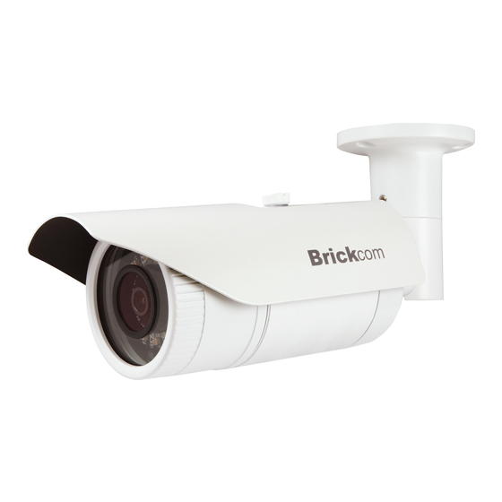
Page 9: Chapter 2 - Bullet Network Camera Overview
Chapter 2 - Bullet Series Network Camera Overview The Brickcom Bullet Series is a Bullet network camera. It adopts a megapixel sensor which allows the camera to deliver extremely clear and detailed images that CCTV cameras cannot offer. To optimize use of the megapixel resolution, the Bullet Series uses efficient H.264/ MJPEG/ MPEG-4 codec compression to deliver dual configurable... -
Page 10: Chapter 3 - Device Appearance Description
Chapter 3 - Device Appearance Description < Front Panel > Lens IR LED Light Sensor < Rear Panel > (*) These are optional features. Please refer to the datasheet for the full list of optional features that are available for this product. - Page 11 Step1. Please remove the sunshade cover and open the front cover. Step2. a. Remove three screws and LED board. b. Remove the three pillars.
- Page 12 Step3.Take the module out. Micro SD card slot and HW Reset Button Reset Button Micro SD Card Slot...
- Page 13 < DI/DO Diagram > < Hardware Reset > Reset Button Micro SD Card Slot...
- Page 14 The Reset Button can be used to reboot the camera or restore it to factory default settings. If the camera experiences a problem, rebooting the camera may correct the problem. If the problem remains, please restore the camera to factory default settings and reinstall the software.
-
Page 15: Chapter 4 - Installation
Chapter 4 - Installation 4.1 Hardware Installation WARNING - Do not mount the camera on a soft material. The camera may fall and be damaged. 1. Micro-SD/SDHC Card a. Remove the sunshade cover and open the front cover.. b. (a)Remove three screws and then take LED board out. (b)Remove the three pillars. - Page 16 c. (1)Insert the Micro SD/SDHC card into their respective slots. (2) Reattach the module and three pillars. Secure the LED board with three screws. Tighten the front cover. Reset Button Micro SD Card Slot...
-
Page 17: Camera Connection
2. Wall Installation Drill three holes on the wall and hammer the supplied plastic anchors into the three holes. Then, use a screwdriver and the supplied screws to screw the camera onto the wall. 3. Camera Connection The camera is DC12V and PoE compliant, so there are two options for powering on the camera. - Page 18 b. Powering on Camera with PoE Injector: i. Use an Ethernet cable to connect the camera to a PoE injector. ii. Use an Ethernet cable to connect the PoE injector to the non-PoE switch. iii. Connect the PoE Injector to a power outlet. c.
-
Page 19: System Requirements
4.2 System Requirements Operating System: Microsoft Windows XP Home Edition SP2 Microsoft Windows XP Professional SP2 Computer: IBM PC/AT Compatible CPU: Pentium 3GHz or faster Memory: 1024 MB or more Monitor: 1024 x 768 pixels or more, 24-bit True color or better Network Interface: 10/100Mbps Network interface card must be installed Web Browser:... -
Page 20: Software Installation
A. Insert the Installation CD into the CD-ROM driver. Run Auto-Run Tool directly from the CD-ROM to start the installation. When installing the Brickcom software kit for the first time, select a desired language for the interface. The available languages are listed in the scroll box. Click <Install>... - Page 21 B. In the Install Shield Wizard dialog box, click <Next> to continue. C. Read the End-User License Agreement and check the option “I accept the terms of the license agreement”. Click <Next> to continue.
- Page 22 D. Select either “Complete” setup or “Custom” setup to install the system. a. If COMPLETE SETUP is selected: i. All program features will be installed into the default directory. Check the option “Complete” and then click <Next>. ii. Click <Change> to change the appointed folder where installation and program files will be stored.
- Page 23 iii. Select to create shortcuts. Click <Next> to continue. iv. The installation information will be displayed. Click <Next> to continue.
- Page 24 v. To launch EasyConfig or PC-NVR Standard, select the application and click <Finish>. When launching the PC-NVR program, please refer to the PC-NVR user manual. b. If CUSTOM SETUP is selected: i. This option is recommended for advanced users. It can be used to install the system to a preferred directory or to select specific program feature(s).
- Page 25 iii. Select the features to install. Click <Next> to continue. iv. Click <Change> to change the appointed folder where installation and program files will be stored. Click <Next> to continue.
- Page 26 v. Select programs to create shortcuts. Click <Next> to continue. vi. The installation information will be displayed. Click <Next> to continue.
- Page 27 E. To launch EasyConfig or PC-NVR Standard, select the application and click <Finish>. When launching the PC-NVR program, please refer to the PC-NVR user manual.
-
Page 28: Easyconfig
If Custom Setup type was used in the software installation and an EasyConfig icon was not installed on the desktop, the program will be installed under C:\Program Files\Brickcom\EasyConfig unless the program was saved to a preferred directory. A. Click <Start> to continue. The program will automatically search for the camera in the intranet. - Page 30 B. Select either “Simple Mode” or “Professional Mode” to obtain the camera’s IP settings. If “Simple Mode” is selected, EasyConfig will set up the connection automatically. If “Professional Mode” is selected, the user will need to configure the IP settings manually.
- Page 31 C. There may be many cameras in the local network. Differentiate the cameras using their UPnP name. Double click on the camera from the survey list to connect. D. For configuring the IP address settings, select either <Settings remain the same>, <Automatically obtain an IP Address (DHCP)>...
- Page 32 If <Set IP Address configuration manually> is selected, the following pages will be displayed.
- Page 33 Otherwise, this page will not be shown. *If desired, click <Skip> to skip this setting. EasyLinkTM is a unique Brickcom function which allows users to assign a unique EasyLink name to their network camera’s IP address. There is no...
- Page 34 F. When the IP address settings have been configured, the screen will either display a successful or failed connection message. If the connection failed, either try again or quit the installation. a. If “DHCP IP address settings” was selected, the failure page will be displayed as below: b.
- Page 35 c. If the connection was successful, the user will see the message: “Congratulations. The installation of the camera is complete.” When this window is displayed, click <PC-NVR> to start the PC-NVR program, <Live View> to view the live video from the connected IP camera, or <X>...
- Page 36 Install the plug-in. Please click to install the ActiveX plug-in on the Internet Explorer. Live View...
Need help?
Do you have a question about the OB-302Ae V5 Series and is the answer not in the manual?
Questions and answers