Advertisement
Quick Links
Download this manual
See also:
User Manual
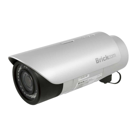
Megapixel Day & Night
Outdoor Bullet Network Camera
OB-100A V2 Series
OB-100A/WOB-100A/GOB-100A
Quick Installation Guide
Quality Service Group
Advertisement

Subscribe to Our Youtube Channel
Related Manuals for Brickcom OB-100A


Summary of Contents for Brickcom OB-100A
-
Page 1: Quick Installation Guide
Megapixel Day & Night Outdoor Bullet Network Camera OB-100A V2 Series OB-100A/WOB-100A/GOB-100A Quick Installation Guide Quality Service Group... - Page 2 Read Before You Use Power camera device immediately if it starts smoking or smells unusual. Power camera device immediately camera exposed to rain or liquid. Do not set the camera device near any heat sources. (Ex: television and oven) Keep the camera device away from direct sunlight.
- Page 3 Do not set the camera device in any wet and humid environments. Do not set the camera device on unsteady surfaces. Do not attempt to dismantle the camera device. Do not drop or hit the camera device. 10. Do not use the camera device when there is lightning.
- Page 4 1. Check Package Contents A. Camera Package contents a. OB-100A b. Shielding Cover c. Screws Bag d. Product CD e. Warranty Card / Easy Installation f. 2 Water Proof Connectors Guide g. Dry Bag h. High Power PoE (Optional) Bracket (Optional) j.
- Page 5 B. Wi-Fi Antenna Package contents (optional) Refer to the installation guide included in the package when installing the Wi-Fi antenna. a. Wi-Fi Dual Band Antenna b. Extension Cable c. Surge Arrestor Kit d. Mount Kit C. 3G Antenna Package contents (optional) Refer to the installation guide included in the package when installing the 3G antenna.
- Page 6 2. Device Description <Front Panel> IR LED Lens Light Sensor <Rear Panel> Shielding Cover Ventilation Hole < Top> Screw Holes...
- Page 7 < Bottom> Screw Holes Secure Hole RJ45 Connector 1 Secure Hole RJ45 Connector 2 Antenna Connector < Side > Micro SD/SDHC Card Slot 3G SIM Card Slot...
- Page 8 3. Installation WARNING: Do not mount the camera on a soft material. The camera may fall and be damaged. Hardware Installation 1 Micro SD/SDHC Card and 3G SIM Card Installation 1.1 Remove the Lens cover from the Bullet Camera. 1.2 Inset the Micro SD/SDHC card and 3G SIM card(*) into their respective slots.
- Page 9 1.4 Reattach the Lens cover and secure the cover to the top of the camera device using two screws.
- Page 10 2 Wall Installation Using the Optional Bracket 2.1 Using the Bracket plate as a guide, drill three holes into the wall and hammer the supplied plastic anchors into the three holes. Use a screwdriver and the supplied screws to secure the plate to the wall. 2.2 Attach the Bracket Assembly Plate to the bottom of the camera using two screws.
- Page 11 2.4 Connect (1) the POE cable; (2) DIDO, Audio In/Out, RS485 cable; and (3) Antenna cable with the camera. Refer to step 4 for more details installation information. 2.5 Secure the two screws on the wall mount bracket. 2.6 Place the wall mount bracket on the plate and attach it using the supplied screws.
- Page 12 3 DIDO, Audio In/Out, RS485, and Antenna Connection 3.1 PoE Connection For the Power over Ethernet connection, construct the PoE cable using the pin definitions of the RJ45 connector below and refer to step 5 for instructions on how to install the Water Proof Connector. Once the PoE cable has been constructed using the waterproof connector, pass the RJ-45 cable from the camera through the bracket and connect it to the PoE cable.
- Page 13 3.2 DIDO, Audio In/Out, RS485 Cable Connection For the DIDO, Audio In/Out and RS485 cable connection, construct an Ethernet cable using the pin definitions of the RJ-45 connector below and refer to step 5 for instructions on how to install the Water Proof Connector.
- Page 14 4 Water Proof Connector Refer to the installation guide included in the package when installing the Water Proof connector 4.1 Insert the stripped cable through the sealing nut and the housing. Clamp the cable with an RJ45 plug. 4.2 Push the RJ45 plug into the housing and secure the sealing nut tightly.
- Page 15 5 Camera Connection The OB-100A is PoE compliant, so there are two options for connecting the camera to a power and Ethernet source. The camera can either be connected to a PoE-enabled switch or a non-PoE switch. A. If using a PoE-enabled switch: Use a single Ethernet cable to connect the camera to the PoE-enabled switch.
- Page 16 C. If using a PoE injector as power input (For GOB-100A, WOB-100A): Use a standard RJ-45 cable to connect the camera to a PoE Injector. Use a standard power cable to connect the PoE Injector to a power outlet.
- Page 17 1. Insert the Installation CD into the CD-ROM driver. Run Auto-Run Tool directly from the CD-ROM to start the installation. When installing the Brickcom software kit for the first time, select a desired language for the interface. The available languages are listed in the scroll box. Click <Install>...
- Page 18 2. To launch EasyConfig or PC-NVR Standard, select the application and click <Finish>. When launching the PC-NVR program, please refer to the PC-NVR user manual.
- Page 19 If Custom Setup type was used in the software installation and an EasyConfig icon was not installed on the desktop, the program will be installed under C:\Program Files\Brickcom\EasyConfig unless the program was saved to a preferred directory. 1. Click <Start> to continue. The program will automatically search for the camera in the intranet.
- Page 21 2. Select either “Simple Mode” or “Professional Mode” to obtain the camera’s IP settings. If “Simple Mode” is selected, EasyConfig will set up the connection automatically. If “Professional Mode” is selected, the user will need to configure the IP settings manually. 3.
- Page 22 4. Enter the username and password of the camera. For first time use, the default username and password are “admin/admin.” 5. For configuring the IP address settings, select either <Settings remain the same>, <Automatically obtain an IP Address (DHCP)> or <Set IP Address configuration manually>. The DHCP setting is recommended.
- Page 23 a. If <Set IP Address configuration manually> is selected, the following pages will be displayed.
- Page 24 *If desired, click <Skip> to skip this setting. EasyLink is a unique Brickcom function which allows users to assign a unique EasyLink name to their network camera’s IP address. There is no need to configure the router to open up ports or remember hard-to-memorize IP addresses.
- Page 25 7. When the IP address settings have been configured, the screen will either display a successful or failed connection message. If the connection failed, either try again or quit the installation. a. If “DHCP IP address settings” was selected, the failure page will be displayed as below: b.
- Page 26 c. If the connection was successful, the user will see the message: “Congratulations. The installation of the camera is complete.” When this window is displayed, click <PC-NVR> to start the PC-NVR program, <Live View> to view the live video from the connected IP camera, or <X>...
Need help?
Do you have a question about the OB-100A and is the answer not in the manual?
Questions and answers