Table of Contents
Advertisement
Quick Links
Advertisement
Table of Contents

Related Manuals for Brickcom OB-E400Af


Summary of Contents for Brickcom OB-E400Af
- Page 1 Hardware User’s Manual Megapixel Day & Night Bullet Network Camera OB-E400Af...
-
Page 2: Table Of Contents
Table of Contents Before You Use This Product ..................1 Regulatory Information ....................2 Chapter 1 - Package Contents ..................3 Chapter 2 - Megapixel Day & Night Bullet Network Camera Overview ..... 4 Chapter 3 - Device Appearance Description ............... 5 Chapter 4 - LED Behavior ............ -
Page 3: Before You Use This Product
Before You Use This Product In many countries, there are laws prohibiting or restricting the use of surveillance devices. This Network Camera is a high-performance, web-ready camera which can be part of a flexible surveillance system. It is the user’s responsibility to ensure that the operation of this camera is legal before installing this unit for its intended use. -
Page 4: Regulatory Information
Regulatory Information Federal Communication Commission Interference Statement This equipment has been tested and found to comply with the limits for a Class B digital device, pursuant to Part 15 of the FCC Rules. These limits are designed to provide reasonable protection against harmful interference in a residential installation. This equipment generates uses and can radiate radio frequency energy and, if not installed and used in accordance with the instructions, may cause harmful interference to radio communications. -
Page 5: Chapter 1 - Package Contents
Chapter 1 - Package Contents Network Camera Screw bag Location sticker Product CD Easy Installation Guide Warranty Card High Power PoE (Optional) Waterproof connector (Please refer to bottom message) The product is intended to be supplied by a Listed Power Unit marked “L.P.S”(or “Limited Power Source”) and rated output 24V AC, 50/60 Hz, 0.7A minimum or 12V DC, 1A minimum or 48V DC, 0.25A minimum”... -
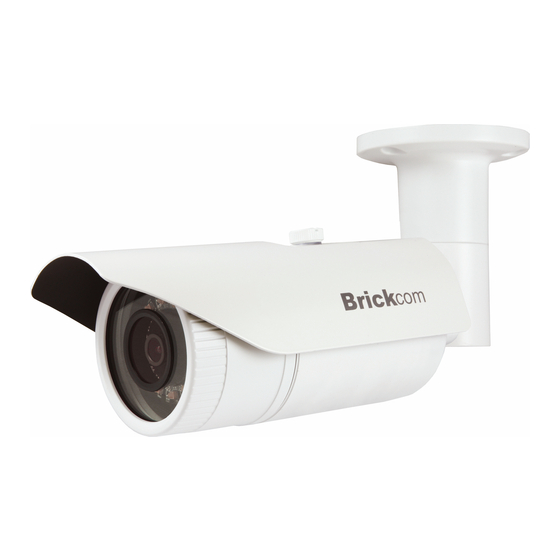
Page 6: Chapter 2 - Megapixel Day & Night Bullet Network Camera Overview
These features make OB-E400Af the perfect outdoor camera for neighborhood, school campus, and parking lot surveillance. The OB-E400Af supports Power over Ethernet and enables the camera to use the same cable for power and data transmission, eliminating the need to install an external power supply. -
Page 7: Chapter 3 - Device Appearance Description
Chapter 3 - Device Appearance Description Lens IR Leds Light Sensor <Hardware Reset> The Reset Button can be used to restore the camera to factory default settings. If the camera experiences a problem, rebooting the camera may correct the problem. If the problem remains, please restore the camera to factory default settings and reinstall the software. -
Page 8: Chapter 5 - Installation
Chapter 4 - Installation 4.1 Hardware Installation Do not mount the camera on any soft material. The camera may fall and be damaged. A compliant waterproof connector shall be attached tightly to the conduit hole of the Vandal Dome Network Camera, and all the cables shall run through the connector for the camera to be IP66-compliant. -
Page 9: Camera Connection
5.2 Camera Connection The Bullet Series is DC12V and PoE compliant, so there are two options for connecting the camera to a power and Ethernet source. The camera can either be connected to a PoE-enabled switch or a non-PoE switch. a. -
Page 10: System Requirements
5.3 System Requirements Operating System: Microsoft Windows 8.1/8/7/Vista/XP/2000 Computer: IBM PC/AT Compatible CPU: Pentium 3GHz or faster Memory: 1024 MB or more Monitor: 1024 x 768 pixels or more, 24-bit True color or better Network Interface: 10/100Mbps Network interface card must be installed Web Browser: Microsoft Internet Explorer 6.0 SP2 or higher Adobe Reader:... -
Page 11: Software Installation
A. Insert the Installation CD into the CD-ROM driver. Run Auto-Run Tool directly from the CD-ROM to start the installation. When installing the Brickcom software kit for the first time, select a desired language for the interface. The available languages are listed in the scroll box. - Page 12 B. In the Install Shield Wizard dialog box, click <Next> to continue. C. Read the End-User License Agreement and check the option “I accept the terms of the license agreement”. Click <Next> to continue.
- Page 13 D. Click <Change> to change the appointed folder where installation and program files will be stored. Click <Next> to continue. E. Select to create shortcuts. Click <Next> to continue.
-
Page 14: Easyconfig
EasyConfig icon was installed on the desktop. Double click to launch EasyConfig. If Custom Setup type was used in the software installation but an EasyConfig icon was not installed on the desktop, by default the program is installed under “C:\Program Files\Brickcom\EasyConfig”. - Page 15 NOTE - Check <Skip the hardware installation guide> to skip checking the hardware connection. To check the hardware installation settings, do not check the option box. 1. Click <Start> to continue. The program will automatically search for the camera in the intranet.
- Page 17 2. Select either <Simple Mode> or <Professional Mode> to obtain the camera’s IP settings. If <Simple Mode> is selected, EasyConfig will set up the connection automatically. If <Professional Mode> is selected, the user will need to configure the IP settings manually. (*Please refer to point 6 for IP setting configuration.) 3.
- Page 18 4. Click <Live view> to view the live video from the connected IP camera, or <X> in the top right corner of the screen to close the installation window. 5. The internet explore will pop out a window to request username and password. For the first-time use, the default username and password are “admin/admin.”...
- Page 19 7. If <Set IP Address configuration manually> is selected, the following pages will be displayed. 8. When the IP address settings have been configured, the screen will either display a successful or failed connection message. If the connection failed, please try again or quit the installation.
Need help?
Do you have a question about the OB-E400Af and is the answer not in the manual?
Questions and answers