Table of Contents
Advertisement
Quick Links
Advertisement
Table of Contents

Related Manuals for EAE EE-6435E


Summary of Contents for EAE EE-6435E
- Page 1 Model No. EE-6435E Installation, Operation Four Post Lift and Parts Manual Electrical Release Lifting Capacity 4000KG / 5000KG Distributed by Please read this entire manual carefully and completely before installation or operation of the lift.
- Page 2 Liability The liability of EAE is limit to the amount that the customer has actually paid for this product. This exclusion of liability does not apply to damages caused through willful misconduct or gross negligence on the part of EAE.
-
Page 3: Table Of Contents
Installation, Operation and Parts Manual EE-6435E IMPORTANT SAFETY INSTRUCTIONS ........................4 1.1 Important notices ................................. 4 1.2 Qualified personnel ..............................4 1.3 Cautions ..................................4 SAFETY WARNINGS ............................... 5 GENERAL DESCRIPTIONS ............................6 3.1 General descriptions ..............................6 3.2 Safety construction ..............................6 3.3 General construction of the lift ............................ -
Page 4: Important Safety Instructions
Installation, Operation and Parts Manual EE-6435E IMPORTANT SAFETY INSTRUCTIONS 1.1 Important notices We will offer one-year's quality warranty for the whole machine,during which any quality problem will be properly solved. However, we will not take any responsibility for whatever bad consequence resulted from improper installation and operation, overload running or unqualified ground condition. -
Page 5: Safety Warnings
Installation, Operation and Parts Manual EE-6435E SAFETY WARNINGS... -
Page 6: General Descriptions
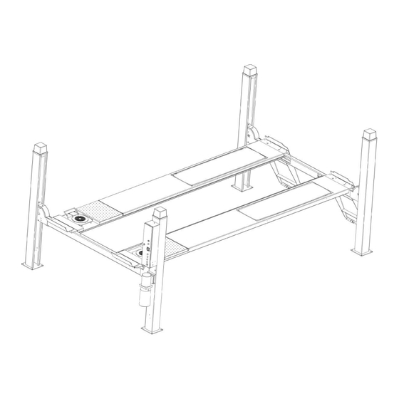
Installation, Operation and Parts Manual EE-6435E GENERAL DESCRIPTIONS 3.1 General descriptions This four post lift is generally composed by four posts, two beams, two platforms, a hydraulic oil cylinder and a set of power unit. It is driven by an electro-hydraulic system. Up and down of platforms is controlled by the to and fro movement of the oil cylinder. To ensure safety of operators, it is equipped with mechanical safety locks in the four posts, which will be automatically engaged in the process of lifting so as to prevent the platforms from sudden dropping down in case the hydraulic system fails to work. -
Page 7: General Construction Of The Lift
Installation, Operation and Parts Manual EE-6435E 3.3 General construction of the lift 1. Platform A 2. Platform B 3. Power side post 1 4. Post2 5. Post3 6. Post4 7. Power side beam 8. Off-side beam 9. Ramps 10. Control box 11. -
Page 8: Installation Instructions
Installation, Operation and Parts Manual EE-6435E INSTALLATION INSTRUCTIONS 4.1 Preparations before installation 4.1.1 Tools and equipments needed Appropriate lifting equipment Anti-abrasion hydraulic oil. Rotary Hammer Drill with 3/4’’ drill bit. Chalk and tape measure, magnetic plump, 8 metersФ15 level pipe. - Page 9 Installation, Operation and Parts Manual EE-6435E Step 2: Fix the installation layout. Once the installation site is determined, mark first the four standing points of the four posts by a tape measure and chalk. Ensure two diagonal lines are of the same length.
- Page 10 Installation, Operation and Parts Manual EE-6435E Step 4: Use the forklift to have the general parts positioned in accordance with following layout. For convenient installation, it would be better to pad something supporting under the platform. Oil cylinder, steel cable and oil hose have already been fixed in the main platform (platform with oil cylinder beneath) before packing.
- Page 11 Installation, Operation and Parts Manual EE-6435E Step5: Connect the platforms and beams Firstly, connect the main beam (the beam which connects to the power side post)with two platforms. Align accurately the screw sockets on the platform and the beam and fasten them by M8*25 inside hex sunken head screw (. Installers can adjust the distance between two platforms on basis of practical needs.
- Page 12 Installation, Operation and Parts Manual EE-6435E 2. Insert the safety rack along the inside surface of end seal plate of the cross beam as showed in the following drawing. 3. Fasten the bottom of the safety rack on to the base plate with M8*20 inside hex cap screw.
- Page 13 Installation, Operation and Parts Manual EE-6435E 5. Fix the safety rack clip on to the swivel section of the safety rack with M5*30 inside hex cylinder head screw and M5 nut. 6. Pull out the steel cables from both ends of the cross beam and fasten them on the top plate of post (please see the Annex for the steel...
- Page 14 Installation, Operation and Parts Manual EE-6435E Step8: Fix the ramps. Align the end of the platform and the hole on the ramp and connect them with shaft and cotter pins. Step9: Fit on four post cap on top of the four post and four beam protection covers at both ends of the two beams.
- Page 15 Installation, Operation and Parts Manual EE-6435E 2. Make electrical and hydraulic connections as per the following diagram.
- Page 16 Installation, Operation and Parts Manual EE-6435E 3. Make hydraulic connections as per the following diagram. Step11: Fill with hydraulic oil (only fresh and clean oil is allowed) Attention: If average temperature of the installation site is higher than 18℃, it is suggested to fill with oil tank with 46# hydraulic oil while the temperature is lower than 18℃, it is suggested to use 32# hydraulic oil.
-
Page 17: Items To Be Checked After Installation
Installation, Operation and Parts Manual EE-6435E 4.4. Items to be checked after installation. Check items Are the posts vertical to the floor? Are the oil hoses well connected? Are the steel cables well connected? Are two platforms well connected? Are electrical connections right? -
Page 18: Descriptions Of Control Panel
Installation, Operation and Parts Manual EE-6435E 5.2 Descriptions of control panel POS. Description Function Alarm buzzer Low height alarm Power switch Control power connection Power indicator Show if power is connected UP button Control the UP movement Safety lock Safety lock engaged... -
Page 19: Operation Instructions
Installation, Operation and Parts Manual EE-6435E 5.4 Operation instructions 5.4.1 Operation instructions for the lift Raise the lift 1. Turn on the power switch. 2. Park the vehicle on the platforms to ensure its gravity is positioned midway of the platforms. -
Page 20: Emergency Lowering In Case Of No Power
Installation, Operation and Parts Manual EE-6435E 5.5 Emergency lowering in case of no power In the case the safety lock is not fully engaged: 1. Push the front rod of the four electric magnets under the cross beam to have the four safety blocks released from the safety rods. -
Page 21: Trouble Shooting
Installation, Operation and Parts Manual EE-6435E TROUBLE SHOOTING ATTENTION: If the trouble could not be fixed by yourself, please do not hesitate to contact us for help .We will offer our service at the earliest time we can. By the way, your troubles will be judged and solved much faster if you could provide us more details or pictures of the trouble. -
Page 22: Maintenance
Installation, Operation and Parts Manual EE-6435E MAINTENANCE Easy and low cost routine maintenance can ensure the lift work normally and safely. Following are requirements for routine maintenance. You may decide the frequency of routine maintenance by consulting your lift’s working conditions and time. -
Page 23: Annex1, Packing List
Installation, Operation and Parts Manual EE-6435E Annex1, Packing list Name Drawing#/size Note Main platform 6435B-A4 Assistant platform 6435B-A5 Beam A 6435M-A2 Beam B 6435M-A7 Guiding plate A 6435B-A8 Guiding plate B 6435B-A10 Post A (power side) 6435B-A1 Post A 6435B-A1... -
Page 24: Annex2, Overall Dimension (Type B)
Installation, Operation and Parts Manual EE-6435E Annex2, Overall dimension (type B) On dimension, type A and S are the same as type B MODEL Dimensions EE-6435B.46L EE-6435B.48L EE-6435B.52L EE-6435B.57L 4560 4800 5200 5700 5708 5948 6348 6848 4648 4888 5288... -
Page 25: Annex3, Steel Cable Connection
Installation, Operation and Parts Manual EE-6435E Annex3, Steel cable connection... -
Page 26: Annex4, Electrical Schemes And Parts List
Installation, Operation and Parts Manual EE-6435E Annex 4, Electrical schemes and parts list Single phase... - Page 27 Installation, Operation and Parts Manual EE-6435E Three phase...
- Page 28 Installation, Operation and Parts Manual EE-6435E...
- Page 29 Installation, Operation and Parts Manual EE-6435E...
- Page 30 Installation, Operation and Parts Manual EE-6435E...
- Page 31 Installation, Operation and Parts Manual EE-6435E...
- Page 32 Installation, Operation and Parts Manual EE-6435E...
- Page 33 Installation, Operation and Parts Manual EE-6435E Spare parts for the electrical system Pos. CODE Name Specification 320101074 Transformer-380V-3P JBK3-400VA 380V-24V 320101071 Transformer-220V-1P( Optional ) JBK3-400VA 220V-24V 320204016 Aluminum motor-3P-3.0KW 380V-3.0KW-3PH-50HZ...
- Page 34 Installation, Operation and Parts Manual EE-6435E Pos. CODE Name Specification 320203001 Aluminum motor-3P-3.5KW( Optional ) 380V-3.5KW-3PH-50HZ 320201004 Aluminum motor-3P-2.2KW( Optional ) 380V-2.2KW -3PH-50HZ-2P 320201001 Aluminum motor -1P-2.2KW( Optional ) 220V-2.2KW-1PH-50HZ-2P SQ1;SQ2 320301009 Limit switch TZ-8104 SQ3-SQ6 320301011 Limit switch TZ8108...
-
Page 35: Annex5, Hydraulic Schemes And Parts List
Installation, Operation and Parts Manual EE-6435E Annex5, Hydraulic schemes and parts list 1.oil tank 2.oil sucking filter 3.gear pump 4.coupling 5.motor 6.hydraulic block 7.cushion valve 8.overflow valve 9.single way valve 10.solenoid unloading valve 11.flow control valve 12.oil tank cover 13.cylinder... - Page 36 Installation, Operation and Parts Manual EE-6435E Pos. CODE Name Specification 623004*** Power unit EE-6435**E 624001008 Rubber oil hose L=4500mm,a bending connector and a straight connector 624001* PU hose 310102013 90 connector with swivel 08N-M14S 615018001 Throttle valve MR30-A24-B16 615027005 5T oil cylinder...
-
Page 37: Annex6, Mechanical Exploded Drawings And Parts List
Installation, Operation and Parts Manual EE-6435E Pos. CODE Name Specification 330302001 Single way valve DYF-C 330304001 Over flow valve EYF-C 310101028 Shift connector G1/4M14x1.5 330301001 Cushion valve HZYF-C1 207103019 Composite washer 210101003 Hex socket flat head fitting M14X1.5 201103001 Hex flange screw... - Page 38 Installation, Operation and Parts Manual EE-6435E Type A Type B...
- Page 39 Installation, Operation and Parts Manual EE-6435E...
- Page 40 Installation, Operation and Parts Manual EE-6435E Pos. CODE Name Specification Comments 202103020 Cross socket flat head screw M8×12 410270101 Shaft block 6435B-A3-B13 420270050 Spacer A 6435B-A3-B1 410270021 Wheel shaft A 6435B-A3-B4 205101070 Bearing 4050 410274120 Wheel A 6435B-A3-B3 420270060 Spacer B...
- Page 41 Installation, Operation and Parts Manual EE-6435E Pos. CODE Name Specification Comments 612027001B Safety rack assembly 6435B-A1-B2 615027006B Steel cable L=12650 (for 46L) 6435B-A3-B29 Φ12 (for 48L) 615027008B 6435B-A3-B29 Φ12 Steel cable L=12890 (for 52L) 615027007B Steel cable L=13290 6435B-A3-B29 Φ12 (for 57L)...
- Page 42 Installation, Operation and Parts Manual EE-6435E Pos. CODE Name Specification Comments Control box Post cap (black) 6435B-A11 420270090 410270033 Ramp B 6435B-A10 203101007 Hex nut optional for type A 615027013 Turntable 6435B-A28,380*380 and B Box (46L) 614027031 6435B-A18 4.6L 5T- Box (4.8L/5.2L/57L)...
- Page 43 Installation, Operation and Parts Manual EE-6435E Pos. CODE Name Specification Comments 614027047 6435A-48L-5T Platform B 5T-6435B-A5 6435A.48L.5t 614027048 6435B-48L-5T Platform B 5T-6435B-A5 6435B.48L.5t 614027044 6435S-52L-5T Platform B 5T-6435B-A5 6435S.52L.5t 614027045 6435A-52L-5T Platform B 5T-6435B-A5 6435A.52L.5t 614027046 6435B-52L-5T Platform B 5T-6435B-A5 6435B.52L.5t...
Need help?
Do you have a question about the EE-6435E and is the answer not in the manual?
Questions and answers