Advertisement
Quick Links
Advertisement

Subscribe to Our Youtube Channel
Related Manuals for Lanner NCA-5530


Summary of Contents for Lanner NCA-5530
- Page 1 Network Appliance Platforms NCA-5530 User Manual Version: 1.1 Date of Release:2021-11-17...
- Page 2 - assumed to be qualified in the servicing of computer equipment, such as professional system integrators, or service personnel and technicians. The latest version of this document can be found on Lanner’s official website, available either through the product page or through the Lanner Download Center page with a login account and password.
- Page 3 Phone support is offered to our customers in the United States and Canada. Toll-free customer service number: +1 855-852-6637 This document is copyrighted © 2021 by Lanner Electronics Inc. All rights are reserved. The original manufacturer reserves the right to make improvements to the products described in this manual at any time without notice.
- Page 4 NCA-5530 User Manual Taiwan Corporate Headquarters China Lanner Electronics Inc. Beijing L&S Lancom Platform Tech. Co., Ltd. 7F, No.173, Sec.2, Datong Rd. Guodong LOFT 9 Layer No. 9 Huinan Road, Xizhi District, New Taipei City 22184, Huilongguan Town, Changping District, Beijing...
- Page 5 NCA-5530 User Manual Intel® and Intel® Celeron® are trademarks of Intel Corporation or its subsidiaries in the U.S. and/or other countries. Microsoft Windows and MS-DOS are registered trademarks of Microsoft Corp. All other product names or trademarks are properties of their respective owners.
- Page 6 NCA-5530 User Manual Follow these guidelines to ensure general safety: Keep the chassis area clear and dust-free during and after installation. Do not wear loose clothing or jewelry that could get caught in the chassis. Fasten your tie or scarf and roll up your sleeves.
- Page 7 The installation of this product must be performed by trained specialists; otherwise, a non-specialist might create the risk of the system’s falling to the ground or other damages. Lanner Electronics Inc. shall not be held liable for any losses resulting from insufficient strength for supporting the system or use of inappropriate installation components.
- Page 8 NCA-5530 User Manual Before turning on the device, ground the grounding cable of the equipment. Proper grounding (grounding) is very important to protect the equipment against the harmful effects of external noise and to reduce the risk of electrocution in the event of a lightning strike. To uninstall the equipment, disconnect the ground wire after turning off the power.
- Page 9 NCA-5530 User Manual Package Content ........................... 11 Optional Accessories ........................11 Ordering Information ........................11 System Specifications ........................12 Front Panel ........................... 14 Rear Panel ............................. 15 Motherboard Information ......................16 Opening the Chassis ........................27 Installing the CPU ......................... 28 Installing the System Memory......................
- Page 10 NCA-5530 User Manual Platform Configuration ......................... 75 Socket Configuration ........................81 Server Mgmt ..........................95 Security ............................100 Boot Menu ..........................103 Save and Exit Menu ........................104 Why Dual BIOS? .......................... 112 Addressing BIOS Start-up Failure with Dual BIOS ..............113 Warranty Policy ..........................
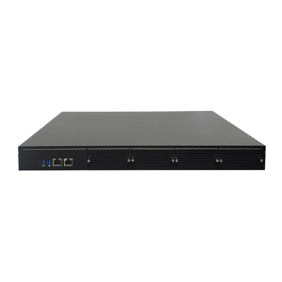
- Page 11 NCA-5530 User Manual NCA-5530 is a high performance 1U rackmount network security system utilizing the cutting-edge capabilities of the Intel Whitley platform and with its I/O versatility and scalability, it is the perfect hardware platform for enhancing network traffic management and virtualized network security. The appliance aims to maximize packet processing efficiency for virtual network functions, cryptography acceleration for deep packet inspection and next-generation firewall and UTM/IPS/IDS applications.
- Page 12 NCA-5530 User Manual Form Factor 1U 19” Rackmount Processor Options Intel® Xeon® Processor Scalable Family (Ice Lake SP) CPU Socket 1x LGA4189 Platform Chipset Intel® C627A / C621A Security Acceleration QuickAssist Technology (NCA-5530A only) BIOS AMI SPI Flash BIOS Technology...
- Page 13 NCA-5530 User Manual Size (WxDxH) 739 x 215 x 582 mm Package Dimensions Weight 18.5kg Type/Watts 550W AC 1+1 Redundant PSU Power Input AC 100V~240V @47~63Hz Approvals and Compliance RoHS Directive (EU) 2015/863, CE/FCC Class A, UL, VCCI, UKCA...
- Page 14 NCA-5530 User Manual F4 F5 F4 F5 Description Reset button 1x Reset Button System Power LED Indicators System Status HDD Activity USB Ports 2x USB 3.0 RJ45 Port 1x RJ45 port Console Port 1x Console port 4x or 2x NCS2 Slim Type Module (By SKU); or...
- Page 15 NCA-5530 User Manual Description Power Supply 2x 550W AC 1+1 Redundant CRPS Power Supply Fans 5x or 4x Hot-swappable Cooling Fans (By SKU) Power Switch 1x Power Switch I/O Button Alarm Reset 1x Alarm Reset Button ESD Jack 1x ESD screw hole...
- Page 16 NCA-5530 User Manual The block diagram indicates how data flows among components on the motherboard.
- Page 17 NCA-5530 User Manual The motherboard layout shows the connectors and jumpers on the board. Refer to the following picture as a reference of the pin assignments and the internal connectors. JFAN4 JFAN3 JFAN2 JFAN1 JFAN5 ATX4 JRISER1A JRISER1B JSATAPW1 JPLD1...
- Page 18 NCA-5530 User Manual The pin headers on the motherboard are often associated with important functions. With the shunt (Jumper) pushed down on the designated pins (the pin numbers are printed on the circuit board, surrounding the pin header), certain feature can be enabled or disabled. While changing the jumpers, make sure your system is turned off.
- Page 19 NCA-5530 User Manual JLPC_80P Pin No. Description Pin No. Description LPC_80PORT_CLK LPC_80PORT_LAD1 LPC_80PORT_RST LPC_80PORT_LAD0 LPC_80PORT_LFRAME +P3V3 LPC_80PORT_LAD3 LPC_80PORT_LAD2 JSPI_TPM1: Pin No. Description Pin No. Description SPI_HD1# SPI_CS1# SPI_CS0# +P3V3_SPI_PCH_AUX SPI_MISO_TPM HEADER_SPI_PCH_IO3 SPI_CLK_TPM SPI_MOSI_TPM IRQ_TPM_SPI#_R SPI_TPM_CS0# RST_PLTRST_PLD_B_N JSATAPW1 & 2: Pin No.
- Page 20 NCA-5530 User Manual JPWR1: Pin No. Description PWRON# JOPEN1: Pin No. Description FM_INTRUDER# JFAN1~5: FAN Connector Pin No. Description Ground +P12V FAN_TECH_IN Sense 2 FAN_TECH_IN Sense 1 FAN_PWM_OUT SW1: Front Panel RST Button SW2: Power ON Button JSATA1~4: SATA Pin No.
- Page 21 NCA-5530 User Manual ATX4: 24 Pin Power Connector Pin No. Description Pin No. Description 12VSB JNGFF3...
- Page 22 NCA-5530 User Manual JIOB1: I/O Board To short the designated pins, push the jumper down on them so that they become SHORT. To make the pins setting OPEN, simply remove the jumper cap. 2-pin Header 3-pin Header 4-pin Header Open...
- Page 23 NCA-5530 User Manual JCLRPAS1 (1-2) 1-2 Normal (Default) 2-3 Password Clear Pin No. Description FM_PW_CLEAR# JMERCVR1 (1-2) 1-2 Normal 2-3 ME Force Update Pin No. Description FM_ME_RCVR_N JCMOS1 (1-2) 1-2 Normal 2-3 Clear CMOS Pin No. Description +VRTC PCH_RTCRST# PD_PCH_RTCRST# JPMB1: PMBUS Pin No.
- Page 24 NCA-5530 User Manual J13 (1-2)1 1-2 Force Boot Up from BIOS (Default) 2-3 Force Boot Up from BIOS2 Pin No. Description +P3V3_AUX BIOS_BOOT_SEL J12 (1-2)1 1-2 Enable dual BIOS (Default) 2-3 Disable dual BIOS Pin No. Description +P3V3_AUX DUAL_BIOS_DIS JCOM2 The power board layout shows the connectors and jumpers on the board.
- Page 25 NCA-5530 User Manual JATX23: 8-pin Power Connector Pin No. Description Pin No. Description P12V P12V P12V P12V J2: MCU Connector Pin No. Description Pin No. Description P1V8LC TDO_4032 TDI_4032 TMS_4032 TCK_4032 CONN1: 2-pin Power Alert Pin No. Description Pin No.
- Page 26 NCA-5530 User Manual ATX4: 24-pin Power Connector Pin No. Description Pin No. Description 12Vsb PWRJ1 & 2: PMBUS Power Connector...
- Page 27 NCA-5530 User Manual To reduce the risk of personal injury, electric shock, or damage to the system, please remove all power connections to shut down the device completely and wear ESD protection gloves when handling the installation steps. 1. Loosen the two (2) thumb screws on the rear panel.
- Page 28 NCA-5530 User Manual Please note that the system delivered to you includes the heatsink and processor. This processor comes with a rather sophisticated design, therefore, the assembly of which must be handled with exclusive tools and extreme care by professionals. Please read through the instructions in this section and refer to the...
- Page 29 NCA-5530 User Manual This is packed along with the processor. Before performing any assembly involving this part, Processor please locate PIN1 on one of the corners, an Carrier important indicator used to align this carrier with the processor and the bolster plate correctly.
- Page 30 NCA-5530 User Manual 2. And line up the two keying features on the processor carrier. 3. Gently press on the each of the press tabs at the top and bottom of the carrier to engage the locking tabs Note: During assembly, it is essential to have (1)PIN1 on the processor carrier aligned with the processor, and (2) the alignment features on the top and the bottom of the processor aligned with the corresponding carrier latches.
- Page 31 NCA-5530 User Manual 5. Align PIN1 of the heatsink to the PIN1 indicator of the processor carrier (if there are two corner cutouts on one heat sink, either will do). 6. Lower the PIN1 end of the heatsink over the processor carrier to engage the two locking tabs near the corners.
- Page 32 NCA-5530 User Manual Installing the PHM onto the Motherboard 1. Remove the socket cover from the socket contacts of the motherboard by grasping the tabs on either side. Squeeze inward Note: Inspect the surface of the socket under sufficient lighting to ensure there is no contamination or damage prior to the PHM installation.
- Page 33 NCA-5530 User Manual 5. Move each anti-tilt wire to outward or locked position. 6. Check the anti-tilt wires are in locked position and have engaged the anti-tilt flanges on the bolster plate. 7. Use a torque driver with a T-30 Torx bit to tighten the four (4) nuts to 8 in/lb in the bolster plate.
- Page 34 NCA-5530 User Manual The motherboard supports DDR4 registered DIMM memory for heavy-duty operations. Please follow the steps below to install the DIMM memory modules. The CPU have 8 DIMM channel sockets (4 on each side) Supported Capacities: 8/16/32/64 GB ⚫...
- Page 35 NCA-5530 User Manual DIMM Population Notes: 1 DIMM: validated on any slot ⚫ 2 DIMM: validated AE, CG, AC, EG, & AD4 ⚫ >2 DIMMs: Channel population can be different than shown as long as symmetric left/Right across the ⚫...
- Page 36 3. Align the notch of the DIMM module with the socket key in the slot. Notch 4. Insert the module into the slot until it is firmly seated. The motherboard of NCA-5530 is designed with eight (8) DDR DIMM sockets. (photo image for reference only)
- Page 37 NCA-5530 User Manual The motherboard provides one TPM slot. Follow the procedures below for installing a TPM module. 1. Power off the system and open the chassis cover. 2. Locate the TPM slot on the motherboard. 3. Insert the TPM module into the pins...
- Page 38 NCA-5530 User Manual NCA-5530 comes with an additional M.2 SSD memory card slot. Please follow the steps for installation. 1. Power off the system and open the chassis cover 2. Locate slot motherboard. 3. Align the notch of the M.2 memory card with the socket key in the pin slot.
- Page 39 NCA-5530 User Manual NCA-5530 is built with two 2.5” HDD/SSD slot drive bay. The following will discuss disk drive installation procedures based on their HDD/SSD designs. 1. Power off the system and open the chassis cover. 2. Locate the 2.5” disk bay.
- Page 40 NCA-5530 User Manual 4. Mount the disk drive onto the empty tray. Make sure the disk drive’s SATA contacts are facing towards the inside the system. SATA Contacts SATA contacts Screws face this side 5. Screw in the hard disk on both sides (two (2) screws on each side).
- Page 41 NCA-5530 User Manual NCA-5530 comes with module slots for LCM module expansion. Please follow the steps below for installation. 1. The LCM module package consists of: 1x LCM Panel 1x LCM connector cable 2x screws LCM Module Screws Connector Cable 2.
- Page 42 NCA-5530 User Manual 6. Install the LCM module into the module slot. 7. Insert the connector cable into the connector pin. 8. Secure the LCM module using the two (2) screws. Close the top cover of the system. The LCM module has been...
- Page 43 NCA-5530 User Manual NCA-5530 comes with NIC Ethernet module slots for network bandwidth expansion. Please follow the steps for installation. 1. Power off the system and open the chassis cover. 2. On the front panel, select a NIC Ethernet module slot.
- Page 44 NCA-5530 User Manual 5. Insert the NIC module. (Module shown in the image is for reference only). 6. Once the module is firmly seated, rotate counter-clockwise and tighten the two (2) lock-screws.
- Page 45 NCA-5530 User Manual The motherboard provides one IPMI slot. Follow the procedures below for installing an IPMI card. Power off the system and open the chassis cover. Locate the IPMI socket on the motherboard. Align the notch of the IPMI card Socket Key with the socket key in the slot.
- Page 46 NCA-5530 User Manual Cooling fans may wear down eventually. Please refer to the steps below for replacing cooling fans. When using a new cooling fan, just reverse the steps to install the fan back onto the enclosure and the system.
- Page 47 NCA-5530 User Manual Power supply units wear down eventually. Please be noted that the NCA-5530 supports only 550W PSU. Please prepare the power supply units matching this capacity. 1. On the rear panel, locate the power supply units and disconnect the power cords.
- Page 48 NCA-5530 User Manual The system can be installed in a rack, with the slidable rails allowing access to the system while solidly securing the system. Please follow the steps below for installation. Attaching the Short Ear Brackets The Ear Brackets come with six screws, as shown below.
- Page 49 NCA-5530 User Manual Attaching Rail Brackets 1. Unpack a slide rail and slide the inner channel to its end. 2. Slide the rail bracket out to its end. 3. To detach the rail bracket from the channel, locate and push the Release Tab on the rail bracket while sliding it out.
- Page 50 NCA-5530 User Manual Installing the Slide Rail Assemblies 1. This slide-rail kit does NOT require screw-fixing. Aim at three (3) available screw holes on the rack front and lock it by clipping the rail’s front end to the post, as shown in the image below. You should hear a “click”...
- Page 51 NCA-5530 User Manual 2. Hold the chassis with its front facing you, lift and gently insert it by aligning with the slide-rail assemblies as shown in the image, and then push the unit into the cabinet. 3. Keep sliding the rails in until they stop about halfway. Press down the metal clips on bother inner channels and push them further into the cabinet.
- Page 52 NCA-5530 User Manual BIOS (Basic Input / Output System) is the program that controls the computer boot process. The system has AMI BIOS built-in, with a SETUP utility that allows users to configure required settings or to activate certain system features. Pressing the <Tab> or <Del> key immediately allows you to enter the Setup utility.
- Page 53 NCA-5530 User Manual Setup main page contains BIOS information and project version information. Feature Description BIOS Vendor: American Megatrends BIOS Core Version: AMI Kernel version, CRB code base, X64 Information Compliancy : UEFI version, PI version BIOS Version : BIOS release version...
- Page 54 NCA-5530 User Manual Select the Advanced menu item from the BIOS setup screen to enter the “Advanced” setup screen. Users can select any of the items in the left frame of the screen.
- Page 55 NCA-5530 User Manual Feature Options Description Enables or disables BIOS support for security device. By disabling this Security Device Enabled function, OS will not show Security Device. TCG EFI protocol and INT1A Disabled Support interface will not be available.
- Page 56 NCA-5530 User Manual Feature Options Description Enables or disables BIOS support for security device. By disabling this Security Device Enabled function, OS will not show Security Device. TCG EFI protocol and INT1A Disabled Support interface will not be available. Enables or disables Security Device.
- Page 57 NCA-5530 User Manual...
- Page 58 NCA-5530 User Manual Feature Options Description Enables or disables BIOS support for security device. By disabling this Security Device Enabled function, OS will not show Security Device. TCG EFI protocol and INT1A Disabled Support interface will not be available. Enabled SHA-1 PCR Bank Enables or disables SHA-1 PCR Bank.
- Page 59 NCA-5530 User Manual...
- Page 60 NCA-5530 User Manual Feature Options Description Enabled Serial Port Enables or disables Serial Port 1. Disabled Device Settings IO=3F8h; IRQ = 4...
- Page 61 NCA-5530 User Manual Feature Options Description Enabled Serial Port Enables or disables Serial Port 2 Disabled Device Settings IO=2F8h; IRQ = 3...
- Page 62 NCA-5530 User Manual...
- Page 63 NCA-5530 User Manual Feature Options Description Smart Fan Mode Smart Fan Parameters None Configuration...
- Page 64 NCA-5530 User Manual Feature Options Description Manual Mode Smart Fan Mode Smart Fan Mode select Smart Fan Mode Target Temperature T1 Input Target Temperature (Range:0 - 127) Target Temperature T2 Input Target Temperature (Range:0 - 127) Target Temperature T3 Input Target Temperature (Range:0 - 127)
- Page 65 NCA-5530 User Manual Feature Options Description COM0 Enabled Enables or disables Console Redirection Console Redirection Disabled...
- Page 66 NCA-5530 User Manual Feature Options Description VT100: ASCII char set VT100+:Extends VT100 to support color, function VT100 keys, etc. VT100+ Terminal Type VT-UTF8:Uses UTF8 encoding to map Unicode VT-UTF8 chars onto 1 or more bytes ANSI ANSI: Extended ASCII char set 9600 Selects serial port transmission speed.
- Page 67 NCA-5530 User Manual Enables VT-UTF8 Combination Key Support for Disabled VT-UTF8 Combo Key Support Enabled ANSI/VT100 terminals With this mode enabled, only text will be sent. Disabled Recorder Mode Enabled This is to capture Terminal data. Disabled Resolution 100x31 Enables or disables extended terminal resolution...
- Page 68 NCA-5530 User Manual Feature Options Description Legacy Serial Select a COM port to display redirection of Legacy COM0 OS and Legacy OPROM Messages Redirection Port 80x24 On Legacy OS, the Number of Rows and Columns Legacy OS Redirection 80x25 supported redirection.
- Page 69 NCA-5530 User Manual Feature Options Description Enables or disables 64bit capable Devices to be Disabled Above 4G Decoding Decoded in Above 4G Address Space (Only if Enabled System Supports 64 bit PCI Decoding) If the system has SR-IOV capable PCIe Devices, this...
- Page 70 NCA-5530 User Manual Feature Options Description Enables Legacy USB support. Enabled Legacy USB Auto option disables legacy support if no USB devices are connected; Disabled Support Auto Disabledoption will keep USB devices available only for EFI applications. Enabled This is a workaround for OSes without XHCI hand-off support. The XHCI...
- Page 71 NCA-5530 User Manual Feature Options Description Disabled Network Stack Enables or disables UEFI Network Stack Enabled Ipv4 PXE Enables Ipv4 PXE Boot Support. If IPV4 is disabled, PXE boot Disabled Enabled option will not be created. Support Ipv4 HTTP Enables Ipv4 HTTP Boot Support. If IPV4 is disabled, HTTP boot...
- Page 72 NCA-5530 User Manual Feature Options Description Disabled CSM Support Enables or disables CSM Support Enabled Do Not Launch Network Controls the execution of UEFI and Legacy PXE OpROM UEFI Legacy Do Not Launch Storage Controls the execution of UEFI and Legacy Storage OpROM...
- Page 73 NCA-5530 User Manual...
- Page 74 NCA-5530 User Manual Feature Options Description Control Legacy PXE Disabled Select On Board LAN# Boot Boot from...
- Page 75 NCA-5530 User Manual Select the Platform menu item from the BIOS setup screen to enter the “Platform Setup” screen. Users can select any of the items in the left frame of the screen. Feature Options Description Displays and provides option to change the PCH Settings...
- Page 76 NCA-5530 User Manual Feature Options Description PCI Express PCI Express Configuration settings None Configuration PCH sSATA None sSATA devices and settings Configuration Power ON Restore AC Power Power Off Select S0/S5 for ACPI state after a G3 Loss Last State...
- Page 77 NCA-5530 User Manual Feature Options Description Enable PCIe root port function swapping feature to PCIe Root Port Disabled dynamically assign function 0 to enabled root port. Function Swapping Enabled MRRS 128B PCIE Max Read Request Size Selection. MRRS 256B Max Read Request...
- Page 78 NCA-5530 User Manual...
- Page 79 NCA-5530 User Manual Feature Options Description Disabled SATA Controller Enables or disables SATA Controller Enabled AHCI Configure SATA as This will configure SATA as RAID or AHCI. RAID Support Aggressive Disabled Link Power Enables or disables SALP Enabled Management Disabled...
- Page 80 NCA-5530 User Manual...
- Page 81 NCA-5530 User Manual Select the “Socket Configuration” menu items from the BIOS setup screen to enter the Socket setup screen. Users can select any of the items in the left frame of the screen. Feature Options Description Processor Displays and provides option to change the Processor...
- Page 82 NCA-5530 User Manual...
- Page 83 NCA-5530 User Manual Feature Options Description Disabled Hyper-Threading Enables Hyper Threading (Software Method to Enabled Enable/Disable Logical Processor threads. [ALL] Disabled Enable or Disable the Machine Check Machine Check Enabled Disabled Hardware Prefetcher = MLC Streamer Prefetcher (MSR 1A4h Bit[0])
- Page 84 NCA-5530 User Manual Feature Options Description CPU Socket0 None None Configuration...
- Page 85 NCA-5530 User Manual Feature Options Description 0: Enable all cores. FFFFFFFFFFF: Disable all cores least Core Disable one core per CPU must be enabled. Disabling all cores is Bitmap(Hex) an invalid configuration.
- Page 86 NCA-5530 User Manual Feature Options Description Auto 1200 1333 1400 1600 1800 1866 2000 2133 2200 Maximum Memory Frequency Selections in Mhz. Do not Memory Frequency 2400 select Reserved 2600 2666 2800 2933 3000 3200 3400-OvrClk 3466-OvrClk 3600-OvrClk 3733-OvrClk...
- Page 87 NCA-5530 User Manual 3800-OvrClk 4000-OvrClk 4200-OvrClk 4266-OvrClk 4400-OvrClk 4800-OvrClk Displays memory topology with Dimm population Memory Topology None information...
- Page 88 NCA-5530 User Manual Feature Options Description Socket0 None Socket0 Configuration Configuration None IOAT Configuration IOAT Configuration Intel® VT for None Intel® VT for Directed I/O (VT-d) Directed I/O (VT-d) PCI-E ASPM Support Per-Port PCI-E ASPM Support (Global) (Global) L1 Only...
- Page 89 NCA-5530 User Manual Feature Options Description Socket 0 Settings related to PCI Express Port 1A None Port 1A Socket 0 Settings related to PCI Express Port 2A None Port 2A Socket 0 Settings related to PCI Express Port 2C None...
- Page 90 NCA-5530 User Manual Feature Options Description None Sck0 IOAT Config None Disable TPH TLP Processing Hint disable Prioritize TPH Disabled Prioritize TPH Enabled Relaxed Ordering Relaxed Ordering Enable/Disable...
- Page 91 NCA-5530 User Manual Feature Options Description Intel® VT for Press <Enter> to bring up the Intel? VT for Directed I/O (VT-d) Configuration menu. Directed I/O (VT-d)
- Page 92 NCA-5530 User Manual Feature Options Description P State Control Configuration Sub Menu, include Turbo, CPU P State Control None XE and etc. CPU C State Control CPU C State setting None...
- Page 93 NCA-5530 User Manual Feature Options Description Disabled SpeedStep(Pstates) Enables or disables EIST (P-States) Enabled Max Performance Select the performance state that the BIOS will set Max Efficient Boot performance mode before OS hand off. Set by Intel Node Manager Disabled...
- Page 94 NCA-5530 User Manual Feature Options Description Disabled CPU C1 auto demotion Autonomous Core C-State Control Enabled Disabled CPU C6 report Enables or disables CPU C6(ACPI C3) report to OS Enabled Enhanced Halt State Core C1E auto promotion Control. Takes effect after Disabled reboot.
- Page 95 NCA-5530 User Manual Feature Options Description Enabled BMC Support Enable or disables interfaces to communicate with BMC. Disabled Wait For BMC response for specified time out. In PILOTII, BMC starts at the same time when BIOS starts during AC Enabled Wait For BMC power ON.
- Page 96 NCA-5530 User Manual If enabled, it starts a BIOS timer which can only be shut Enabled off by Management Software after the OS loads. It also OS Watchdog Timer Disabled helps verify that the OS is successfully loaded or follows the OS Boot Watchdog Timer policy.
- Page 97 NCA-5530 User Manual Feature Options Description Disabled Enables or disables all features of System Event SEL Components Enabled Logging during boot. Erase SEL Choose options for erasing SEL. Yes, On next reset Yes, On every reset Do Nothing When SEL is Full Choose options for reactions to a full SEL.
- Page 98 NCA-5530 User Manual Feature Options Description Select to configure LAN channel parameters Unspecified Configuration Address statically or dynamically (by BIOS or BMC). The Static unspecified option will not modify any BMC source DynamicBmcDhcp network parameters during BIOS phase.
- Page 99 NCA-5530 User Manual...
- Page 100 NCA-5530 User Manual Select the “Security” menu item from the BIOS setup screen to enter the Security setup screen. Users can select any of the tiems in the left frame of the screen. Feature Description If ONLY the Administrator's password is set, it only limits Administrator Password access to Setup and is only asked for when entering Setup.
- Page 101 NCA-5530 User Manual Feature Options Description Secure Boot is activated when Platform Key(PK) is Disabled Secure Boot enrolled, System mode is User/Deployed, and CSM Enabled function is disabled. Secure Boot mode selector: Standard Secure Boot Mode In Custom mode, Secure Boot Variables can be...
- Page 102 NCA-5530 User Manual Feature Options Description Provision factory default keys on next re-boot only when Disabled Factory Key Provision Enabled System in Setup Mode. Force System to User Mode. Configure NVRAM to Restore Factory keys None contain OEM-defined factory default Secure Boot keys.
- Page 103 NCA-5530 User Manual Select the “Boot” menu item to enter the Boot setup screen. Users can select any of the items on the left frame of the screen. Feature Options Description The Number of seconds to wait for setup activation key.
- Page 104 NCA-5530 User Manual Select the “Save & Exit” menu to enter the Save and Exit setup screen. Users can select any of the items on the left frame of the screen. ■Discard Changes and Exit Select this option to quit Setup without saving any modifications to the system configuration. The following window will appear after the “Discard Changes and Exit”...
- Page 105 NCA-5530 User Manual ■Save Changes and Reset When Users have completed the system configuration changes, select this option to save the changes and reset from BIOS Setup in order for the new system configuration parameters to take effect. The following window will appear after selecting the “Save Changes and Reset”...
- Page 106 NCA-5530 User Manual System Power / Status / HDD Activity COLOR COLOR LED ACTION DESCRIPTION ON LCM ON BOARD POWER Green Green Steady When system power on No power on STATUS Green Green Steady control by GPIO Amber Steady control by GPIO...
- Page 107 NCA-5530 User Manual 1Gb RJ-45 Define: Speed Amber (Active) Green/Amber (Link) Blinking / Data access 100M Blinking / Data access ON (Green) Blinking / Data access ON (Amber) 1. When cable is plug-in and network is linked. Both LED will be bright. The behavior is as defined.
- Page 108 NCA-5530 User Manual Fiber LAN LED – SFP, SFP+, SFP28, QSFP+, QSFP28 Fiber LED: RX or TX cable status (By Project) On board LED: Status SFP 1G (Amber) SFP+ 10G (Green) Link ON (Amber) ON (Green) Active Blinking / Data access...
- Page 109 NCA-5530 User Manual (1Gb) SFP Light pipe LED (top location) Speed Amber (Active) Amber Green (Link) Blinking / Data access ON (Amber) Non-Link 1. When cable is plug-in and network is linked. Both LED will be bright. The behavior is as defined.
- Page 110 NCA-5530 User Manual (25Gb) SFP28 Light pipe LED (top location) Speed Green (Active) Amber Green (Link) Blinking / Data access ON (Green) 1. When cable is plug-in and network is linked. Both LED will be bright. The behavior is as defined.
- Page 111 NCA-5530 User Manual LAN Bypass LED Define and Default Configuration Define Bypass LED 1 LED per pair, reserve on board 1x2 pin header per port. (Standard device does NOT include the LED as default) (If Standard device require LED, when Bypass is Enable, the...
- Page 112 Eventually, users are left with no choice but to ship the board back to the manufacturer. Lanner understands this pain and has empowered our products with the Dual BIOS feature. Normally, the Primary BIOS is used to boot the OS during powering up, however, when the Primary BIOS is down, the Secondary BIOS automatically jumps in to boot up the OS for the user to take further steps such as performing data backup and BIOS upgrade.
- Page 113 2 minutes, depend upon appliance), the system will invoke a bootup from the Secondary BIOS, automatically restarting the system and launch the operating system. To provide increased flexibility and usage protection, Lanner has released the 2 Gen Dual BIOS function on Lanner appliances.
- Page 114 ME code variations on both of the BIOS, which can lead to unexpected risks and errors. Disclaimer Under no circumstances will Lanner accept responsibility or liability for damages of any kind whatsoever resulting or arising directly or indirectly from a BIOS update.
- Page 115 NCA-5530 User Manual APPENDIX C: REDUNDANT POWER MODULE BEHAVIOR Define Alarm and Mute behavior Power Module Power Module Power Cord Fail Remove Remove Buzzer Alarm Alarm Alarm Change back the Good PSU Module Put back the PSU Module Plug-in the Power cord...
-
Page 116: Appendix D: Fan Sequence
NCA-5530 User Manual APPENDIX D: FAN SEQUENCE Define the Sequence of the Fan Fan Sequence – The detection is from the left to the right side, from the bottom to the top side. Example:... - Page 117 NCA-5530 User Manual APPENDIX E: SMART POWER AND RESET BUTTON Smart Power and Reset Button – Control by CPLD...
- Page 118 NCA-5530 User Manual APPENDIX F: ESD/SURGE ENHANCEMENT Electrostatic Discharge (ESD): Contact Discharge Air Discharge IEC-61000-4-2 Level 1 ±2 kV ±2 kV Level 2 ±4 kV ±4 kV 4K Contact Level 3 ±6 kV ±8 kV 8K Air Level 4 (TBD) ±8 kV...
-
Page 119: Appendix G: Terms And Conditions
NCA-5530 User Manual APPENDIX G: TERMS AND CONDITIONS 1. All products are under warranty against defects in materials and workmanship for a period of one year from the date of purchase. 2. The buyer will bear the return freight charges for goods returned for repair within the warranty period;... - Page 120 NCA-5530 User Manual When requesting RMA service, please fill out the following form. Without this form enclosed, your RMA cannot be processed.
Need help?
Do you have a question about the NCA-5530 and is the answer not in the manual?
Questions and answers