
Related Manuals for Lanner NCA-2513


Summary of Contents for Lanner NCA-2513
- Page 1 Network Computing Innovative Platforms for Next Generation Network Infrastructure NCA-2513 User Manual Version: 1.0 Date of Release: 2020-08-04...
- Page 2 Warning: This exclamation point indicates that there is a caution or warning and it is something that could damage your property or product. Online Resources The listed websites are links to the online product information and technical support. Resources http://www.lannerinc.com Lanner http://www.lannerinc.com/download- Product Resource center http://eRMA.lannerinc.com Copyright and Trademarks This document is copyrighted ©...
- Page 3 Compliances and Certification This product has passed the CE test for environmental specifications. Test conditions for passing included the equipment being operated within an industrial enclosure. In order to protect the product from being damaged by ESD (Electrostatic Discharge) and EMI leakage, we strongly recommend the use of CE-compliant industrial enclosure products.
- Page 4 Lithium Battery Caution: Risk of Explosion if Battery is replaced by an incorrect type. Dispose of used batteries according to the instructions. Installation only by a trained electrician or only by an electrically trained person who knows all English Installation and Device Specifications which are to be applied. Do not carry the handle of power supplies when moving to another place.
- Page 5 Lanner Electronics Inc. shall not be held liable for any losses resulting from insufficient strength for supporting the unit or use of inappropriate installation components. Installation & Operation: The installation of this product must be performed by trained specialists; otherwise, a non-specialist might create the risk of the system’s falling to the ground or other damages.
- Page 6 Vérifiez que le couvercle du châssis est bien fixé. La conception du châssis permet à l’air de refroidissement de bien circuler. Un châssis ouvert laisse l’air s’échapper, ce qui peut interrompre et rediriger le flux d’air frais destiné aux composants internes. Les décharges électrostatiques (ESD) peuvent endommager l’équipement et gêner les circuits électriques.
- Page 7 Battery Precautions Lithium Battery Caution: There is danger of explosion if the battery is incorrectly replaced. Replace only with the same or equivalent type. Dispose of batteries according to the manufacturer's instructions. Disposal of a BATTERY into fire or a hot oven, or mechanically crushing or cutting of a BATTERY can result in an EXPLOSION.
-
Page 8: Table Of Contents
Table of Contents Chapter 1: Product Overview ............9 Chapter 2: Motherboard Information ..........14 Chapter 3: Hardware Setup ............. 26 Chapter 4: BIOS Setup ..............39 Appendix A: Setting up Console Redirections ....... 80 Appendix B: Installing Intel® LAN Controller Driver for Linux ..81 Appendix C: Terms and Conditions .......... -
Page 9: Chapter 1: Product Overview
Intel® Atom™ C3000 Series CPU (codenamed Denverton) with up to 8 cores of processing prowess. Featuring 6~8 LAN ports, 1x NIC module slot, optional LTE module and 150W PSUs, NCA-2513 is the ideal hardware platform for uCPE, SD-WAN and edge computing with mobile connectivity... - Page 10 Intel C3338R 2 Core with QAT + 6x GbE + 1x NIC (1x PCIex4) Optional Accessories Model Description Riser KIT FOR NCA-2513 Riser Card KIT for the rear slot PGN LTE KIT FOR NCA-2513 LTE KIT WIFI KIT FOR NCA-2513 WIFI KIT Slide rail Slide rail KIT...
- Page 11 1 x Pigeon LTE module support (Optional) mini-PCIe / M.2 1 x mini-PCIe Watchdog Miscellaneous Internal RTC with Li-Battery Yes (Onboard) Processor Passive CPU heatsink Cooling System 1x smart fans 0 to 40ºC Operating Temperature -20 to 70ºC Non-Operating Environmental Parameters 5 to 90% Operating Humidity (RH) 5 to 95% Non-Operating...
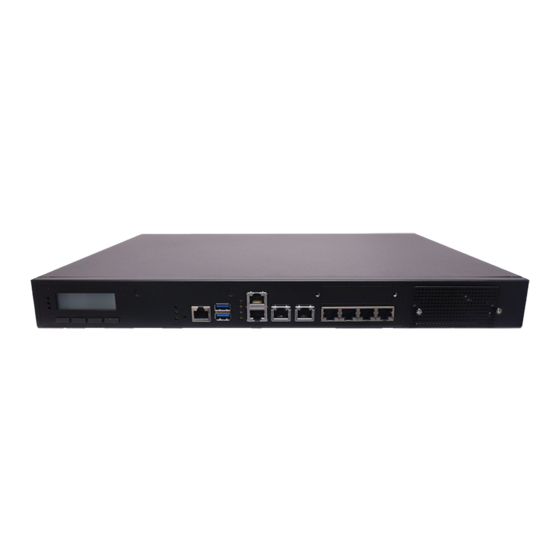
- Page 12 Front Panel NCA-2513 F4 F5 Description With a Keypad System Power LED Indicators System Status HDD Activity Software reset Reset Button Console Port 1x Console port USB Port 2x USB 3.0 port (By SKU) Speed LAN LED Link/Active Indicators Speed...
- Page 13 Rear Panel Description Rear PCIe Expansion 1x PCIex8 Expansion slot (Riser card required) (FH/HL) (By SKU) Cooling Fans 1x smart fan Power Button 1x ATX Power button Power Supply 1x 150W PSU...
-
Page 14: Chapter 2: Motherboard Information
CHAPTER 2: MOTHERBOARD INFORMATION Block Diagram The block diagram indicates how data flows among components on the motherboard. Please refer to the following figure for your motherboard’s layout design. MiniPCIE M.2 2280 SATA SSD Support upto 64GB ECC/non-ECC DDR4 Long-DIMM (2DPC) Support PGN Module(USB 3.0 Signal) 1xPCIE/USB2.0 SATA3.0... - Page 15 Motherboard Layout The motherboard layout shows the connectors and jumpers on the board. Refer to the following picture as a reference of the pin assignments and the internal connectors. MPCIE1 COMB2...
- Page 16 Internal Jumper & Connectors JRTC1:SRTC reset Description 1-2 (Default) Normal Clear CMOS JRTC2:RTEST reset Description 1-2 (Default) Normal Clear CMOS JRESET1:RESET option Description Hardware Reset 2-3(Default) Software Reset JATX1:AT/ATX Mode selection Action Description w/o Jumper ATX mode w/ Jumper(default) AT mode J8:GEN3 LAY Bypass programming Description 1-2 (Default)
- Page 17 Pin Assignment of Power ATX1: Power Supply Connector PIN NO. DESCRIPTION PIN NO. DESCRIPTION +3.3V +3.3V +3.3V -12V PSON ATXPWGD 5VSB +12V +12V +3.3V SATAPWR1: SATA Power Connector 1x4 Pins 2.54mm Pin number Pin signal Ground Ground 4 3 2 1...
- Page 18 Pin Assignment of External Port RJ3~RJ4: Single RJ45 w/ transformer Pin number Pin signal In/Out MD0+ MD0- MD1+ MD2+ MD2- MD1- MD3+ MD3- RJ1_2: Stack 1x2 RJ45 w/ transformer Pin number Pin signal In/Out MD0+ MD0- MD1+ MD2+ MD2- MD1- MD3+ MD3- LAN5_8: 1x4 RJ45 w/o transformer...
- Page 19 SFP1_2: Stack Fiber CONN DESCRIPTION DESCRIPTION TX Fault TX Disable MOD_DEF2/SDA (DATA) MOD_DEF1/SCL (CLK) VCC_R (PWR2) ABS_N VCC_T (PWR1) RX_LOS COM1 : RJ45 Console Pin number Pin signal In/Out Request To Send (RTS) Data Terminal Ready (DTR) Transmitted Data (TxD) Signal Ground Signal Ground Received Data (RxD)
- Page 20 Pin Assignment of Internal Header/Socket JSATA1~2:180º SATA CONNECTOR PIN NO. DESCRIPTION MPCIE1: MiniPCIE Socket Description Description VCC3 VCC1P5 SMB_CLK VCC1P5 SMB_DATA CLKREQ USB_D- REFCLK- USB_D+ REFCLK+ VCC3 VCC3 PH, VCC3 RSEST VCC1P5 VCC3 VCC3...
- Page 21 JPCIE1: PCIe x8 G/F Side B Side A +12V +12V +12V +12V +12V SMB_CLK SMB_DAT P3V3 SOC_GPIO6 P3V3 P3VSB P3V3 WAKE# PLTRST_PCIE_N CLK100_PCIE_SLOT1_1P PCIE_CTX_C_SLOT1RX_N7 CLK100_PCIE_SLOT1_1N PCIE_CTX_C_SLOT1RX_P7 PCIE_SLOT1TX_C_CRX_N7 PCIE_SLOT1TX_C_CRX_P7 PCIE_CTX_C_SLOT1RX_N6 PCIE_CTX_C_SLOT1RX_P6 PCIE_SLOT1TX_C_CRX_P6 PCIE_SLOT1TX_C_CRX_N6 PCIE_CTX_C_SLOT1RX_N5 PCIE_CTX_C_SLOT1RX_P5 PCIE_SLOT1TX_C_CRX_N5 PCIE_SLOT1TX_C_CRX_P5 PCIE_CTX_C_SLOT1RX_N4 PCIE_CTX_C_SLOT1RX_P4 PCIE_SLOT1TX_C_CRX_N4 CLK100_PCIE_SLOT1_2P PCIE_SLOT1TX_C_CRX_P4 CLK100_PCIE_SLOT1_2N PCIE_CTX_C_SLOT1RX_N3...
- Page 22 M2_STORAGE: M.2 B - key Description Description +P3V3 +P3V3 mSATA_RX_DP2 mSATA_RX_DN2 mSATA_TX_DN2 mSATA_TX_DP2 RESET# +P3V3 +P3V3 +P3V3...
- Page 23 JPMBUS1 : PMBUS 1x8 2.0mm w/ wafer Pin number Pin signal In/Out TTL1 TTL2 PMBUS_CLK PMBUS_DATA SMB_LEG_ALRT_N JLCM1: LCM module 2x12 2.0mm Description Description SLIN INIT LCD_N KPA1 KPA2 KPA3 KPA4 CRT_GRN CTR_YLW HD_LED PGN1: 2x10 box header 2.0mm Description Description V5USB USB3_RX1_N...
- Page 24 FAN1~2: 5Pin FAN connector Pin No. Description FANIN1 FANIN2 FANOUT COMB2:COM Port 2.0 mm Pin Header SMD 2x5, KEY10 PIN NO. DESCRIPTION Data Carrier Detect ( DCDA # ) Data Set Ready ( DSRA # ) Receive Data ( RXDA ) Request To Send ( RTSA # ) Transmit Data ( TXDA ) Clear To Send ( CTSA # )
- Page 25 Pin Assignment of Debug/Sample development JSPIROM1: 2.0mm SMD Pin header SMD 2X5 Description Description SPI_HD1# SOC_SPI_CS0#_ROM V_3P3_SPI SOC_SPI_MISO_ROM SOC_SPI_IO3_ROM SOC_SPI_CLK_ROM SOC_SPI_MOSI_ROM J80PORT1: 2.0mm Pin header 2x5 DESCRIPTION DESCRIPTION LAD1 RST- LAD0 LRAME- P3V3 LAD3 LAD2 CON2: GEN3 Bypass programming pin header Description P3VSB...
-
Page 26: Chapter 3: Hardware Setup
Opening the Chassis 1. Power off NCA-2513 completely. 2. Remove the two screws at the rear, as circled in the figures below. 3. Slide and pull the top compartment as the arrow of direction below. - Page 27 Installing the System Memory The motherboard supports 2 memory slots for DDR4 UDIMM with speeds up to 2666MHz. The CPU requires at least 2 memory modules to boot and run from. Supported System Memory Summary Total Slots Number of Channels 2 (2 DIMMs per channel) Supported DIMM Capacity 4GB, 8GB, 16GB, 32GB...
- Page 28 NCA-2513 User Manual Installing the M.2 Storage Card This system supports the M.2 storage module (2242 B Key) through the M2_1 slot. 1. Locate the M2_1 slot. 2. Insert the M.2 module into the slot at 15° angle, align the notch on the module with the corresponding socket key in the slot, and then secure it with a screw.
- Page 29 Installing the NIC Modules This system can accommodate one NIC slim type modules at the front and another one at rear FH/HL PCIe expansion slot. Based on your application requirements, employ a combination of Riser Cards to fulfill your needs: 1.
- Page 30 NCA-2513 User Manual Installing Mini PCI-E Module 1. Locate the Mini PCI-E module slot on the motherboard. Mini- PCI-E 2. Align the notch of the module with the socket key in the slot. Tilt the end of the golden fingers down while carefully inserting the card into the slot. Press vertically on the other end of the card until it clicks into place.
- Page 31 Installing the Hard Disks The system can accommodate two 2.5” SSD/HDD at its front disk bay. With the optional SSD swappable cage, you can add another two SSD disks for system storage. After you install the hard drives, make sure the SATA data cables and SATA power cables are connected to the designated connectors on the motherboard, as indicated in the picture below.
- Page 32 NCA-2513 User Manual 2. Place the disk drive in the tray, as shown in the image below. Apply two disk screws with two rubber washers for each side of the disk drive. If you are going to install two disks, always start by installing the disk in the lower slot.
- Page 33 Mounting the System There are two methods for installing this system into a rack: With Mounting Ear Brackets only This method is quick and easy by fixing this system to the front posts of the rack, but it also makes servicing the system more difficult. Please note that the use of these brackets must go with a rack shelf or slide rails to prevent the chassis from falling over, for the bracket assembly alone cannot provide sufficient support to the chassis.
- Page 34 NCA-2513 User Manual Installing the System Using Mounting Ear Brackets Only 1. Check the accessory pack for the following items: 1x Screw Pack 2x Ear Brackets 2. Align the bracket to the side of the chassis and make sure the screw-holes are matched, and then secure the bracket onto the chassis with three provided screws.
- Page 35 Installing the System Using the Slide Rail Kit (with Mounting Ear Brackets) 1. Check the package contents of the Slide Rail Kit. The kit shall include the following items: 1x pack of M4X4L screws (for securing the Rail Brackets on the system) 1x pack of 7.1 Round Hole screws (for securing the system on...
- Page 36 NCA-2513 User Manual 5. Align the bracket to the side of the chassis and make sure the screw- holes are matched, and then secure the bracket onto the chassis with three provided M4X4L screws. Align the screws with the holes indicated on the brackets and the screw holes on the side of the chassis.
- Page 37 9. For the rear rack installation, slide the rail to aim and engage the bolts on the rail’s rear end with the two available holes on the post, and the rail assembly will click into place. Click 10. Stretch both of the Inner Rails out to their fullest extent.
- Page 38 NCA-2513 User Manual 12. While pushing in the system, also push and hold the Rail Lock tab on both brackets. Rail Lock Push the system all the way in until it stops. To remove the system from the rack, gently pull it outwards, towards you, while pushing the Release Tab on both sides of the brackets.
-
Page 39: Chapter 4: Bios Setup
CHAPTER 4: BIOS SETUP Enter BIOS Setup To enter the BIOS setup utility, simply follow the steps below: 1. Boot up the system. 2. Press <Delete> during the boot-up if you connect a keyboard to this unit. But if you connect a PC to this unit through console USB/Serial connection, then press <Tab>. - Page 40 NCA-2513 User Manual Main Page Setup main page contains BIOS information and project version information. Feature Description BIOS Vendor: American Megatrends Core Version: AMI Kernel version, CRB code base, X64 BIOS Compliancy: UEFI version, PI version Information Project Version: BIOS release version...
- Page 41 Advanced Page Select the Advanced menu item from the BIOS setup screen to enter the “Advanced” setup screen. Users can select any of the items in the left frame of the screen.
- Page 42 NCA-2513 User Manual Trusted Computing...
- Page 43 Feature Options Description Enables or disables BIOS support for security device. Security Device Enabled By disabling this function, OS will not show Security Support Disabled Device. TCG EFI protocol and INT1A interface will not be available. Enabled SHA-1 PCR Bank Enables or disables SHA-1 PCR Bank.
- Page 44 NCA-2513 User Manual Super IO Configuration...
- Page 45 Serial port 1 Configuration Feature Options Description Enabled Serial Port Enables or disables Serial Port 1. Disabled Device Settings IO=3F8h; IRQ = 4...
- Page 46 NCA-2513 User Manual Serial port 2 Configuration Feature Options Description Serial Port Enabled Enable or Disable Serial Port 2. Disabled Device Settings IO=2F8h; IRQ = 3...
- Page 47 Parallel Port Configuration Feature Options Description Parallel Port Enabled Enable or Disable Parallel Port. Disabled Device Settings IO=378h; IRQ = 5...
- Page 48 NCA-2513 User Manual H/W Monitor...
- Page 49 Watch Dog Timer Configuration Feature Options Description Watch Dog Enabled Enables or disables Watch Dog Timer function Timer Disabled...
- Page 50 Status LED Configuration Feature Options Description Status LED GREEN Configures Status LED color...
- Page 51 Serial Port Console Redirection Feature Options Description COM0 Enabled Console Enables or disables Console Redirection Disabled Redirection...
- Page 52 Console Redirection Settings Feature Options Description VT100: ASCII char set VT100 VT100+:Extends VT100 to support color, VT100+ function keys, etc. Terminal Type VT-UTF8 VT-UTF8:Uses UTF8 encoding to map Unicode ANSI chars onto 1 or more bytes ANSI: Extended ASCII char set 9600 19200 Selects serial port transmission speed.
- Page 53 Stop Bits Indicates the end of a serial data packet. None Flow Control can prevent data loss from Flow Control Hardware buffer overflow. RTS/CTS VT-UTF8 Combo Key Disabled Enables VT-UTF8 Combination Key Support for Support Enabled ANSI/VT100 terminals Disabled With this mode enabled, only text will be sent. Recorder Mode Enabled This is to capture Terminal data.
- Page 54 Console Redirection Settings Feature Options Description Redirection COM COM0 Select a COM port to display redirection of Legacy Port OS and Legacy OPROM Messages. 80x24 On Legacy OS, the Number of Rows and Resolution 80x25 Columns supported redirection. When Bootloader is selected, Legacy Console Redirection is disabled before booting to Always Redirection After...
- Page 55 PCI Subsystem Settings Feature Options Description Enable or Disables 64bit capable Devices to be Above 4G Disabled Decoded in Above 4G Address Space (Only if System Decoding Enabled Supports 64 bit PCI Decoding). Feature Options Description If the system has SR-IOV capable PCIe Devices, this Disabled SR-IOV Support option...
- Page 56 2.3.1 Network Stack Configuration Feature Options Description Disabled Network Stack Enables or disables UEFI Network Stack Enabled Disabled Enables Ipv4 PXE Boot Support. If IPV4 is disabled, Ipv4 PXE Support Enabled PXE boot option will not be created. Disabled Enables Ipv4 HTTP Boot Support. If IPV4 is Ipv4 HTTP Support Enabled disabled, HTTP boot option will not be created.
- Page 57 CSM Configuration Feature Options Description Disabled CSM Support Enables or disables CSM Support Enabled Do Not Launch Controls the execution of UEFI and Legacy Network UEFI PXE OpROM Legacy Do Not Launch Controls the execution of UEFI and Legacy Storage UEFI Storage OpROM Legacy...
- Page 58 USB Configuration Feature Options Description Enables Legacy USB support. Enabled Auto option disables legacy support if no USB Legacy USB Disabled devices are connected; Support Auto Disabled option will keep USB devices available only for EFI applications. This is a workaround for OSes without XHCI hand- Enabled XHCI Hand-off off support.
- Page 59 Maximum time the device will take before it properly Device power- Auto reports itself to the Host Controller. Auto uses up delay Manual default value: for a Root port, it is 100 ms, for a Hub port the delay is taken from Hub descriptor.
- Page 60 Control Legacy PXE Boot (For : SKU-A) Feature Options Description Control Legacy PXE Boot from which Control Legacy PXE Disabled Lan. Boot From Lan2 Lan3...
- Page 61 Control Legacy PXE Boot (For : SKU-C) Feature Options Description Control Legacy PXE Boot from which Control Legacy PXE Disabled Lan. Boot From Lan0 Lan1...
- Page 62 IntelRCSetup Select the IntelRCSetup menu item from the BIOS setup screen to enter the Platform Setup screen. Users can select any of the items in the left frame of the screen. Feature Options Description Relax Security Disable Relaxes the security configuration to be Configuration Enabled able to use BIOS update tool.
- Page 63 Processor Configuration Feature Options Description Disable Enables/Disable EIST. GV3 must be EIST (GV3) Enable enable for Turbo. Enable or Disable CPU Turbo capability. Enable Turbo This option only applies to ES2 and Disable above. Disable Enable the Enhanced Cx state of the CPU, CPU C State Enable takes effect after reboot.
- Page 64 L1 Prefetcher Enable Enable/Disable L1 Prefetch. Disable L2 Prefetcher Enable Enable/Disable L2 Prefetch Disable Fast String Disable When enables, enable fast strings for REP Enable MOVS/STOS. Machine Check Disable Enable or Disable the Machine Check. Enable Execute Disable Bit Disable When disabled, forces the XD feature flag Enable to always return 0.
- Page 65 North Bridge Chipset Configuration Feature Options Description Enables/Disables fast boot which skips memory Disabled Fast Boot training and attempts to boot using fast known good Enabled configuration. Memory DDR-1600 DDR memory frequency: Frequency DDR-1867 DDR4 up to DDR-2666 DDR-2133 DDR3 up to DDR-1867. DDR-2400 VT-d Disable...
- Page 66 South Bridge Chipset Configuration...
- Page 67 SATA Configuration Feature Options Description Enable controller Enabled Enables/Disables SATA Controller if supported by current CPU sku Enabled Enables/Disables Link Power Management Disabled ALPM Enabled Enable/Disables Agresive Link Power Management Disabled Speed Limit Gen 1 Indicates the highest allowable speed of the interface Gen 2 Gen 3...
- Page 68 SATA1 on Controller port Feature Options Description Enable/disable port Enabled Enables/Disables SATA Controller port if Disabled supported by current cpu SKU. Hot plug Enabled Hot plug Disabled Spin up Enabled Spin up Disabled...
- Page 69 SATA2 on Controller port Feature Options Description Enable/disable port Enabled Enables/Disables SATA Controller port if Disabled supported by current cpu SKU. Hot plug Enabled Hot plug Disabled Spin up Enabled Spin up Disabled...
- Page 70 M2SATA on Controller port Feature Options Description Enable/disable port Enabled Enables/Disables SATA Controller port if Disabled supported by current cpu SKU. Hot plug Enabled Hot plug Disabled Spin up Enabled Spin up Disabled...
- Page 71 PCIE IP Configuration Feature Options Description Bifurcation PCIE0 Auto Select and force Root Complex Bifurcation Configuration regardless board or trident x4x4 detection. x4x2x2 X2x2x4 X2x2x2x2 Bifurcation PCIE1 Auto Select and force Root Complex Bifurcation Configuration regardless board or trident X4x4 detection.
- Page 72 IQAT Configuration Feature Options Description IQAT Enabled Hides IQAT device from and OS.. Disabled...
- Page 73 System Event Log Feature Options Description System Errors Disable System Error enabling and logging setup Enable option. Auto WHEA Support Disable Enable/Disable WHEA ACPI support. Enable WHEA Error Injection Disable When EINJ ACPI 5.0 support for set error 5.0 Extension Enable type with address and vendor extensions.
- Page 74 Security Select the Security menu item from the BIOS setup screen to enter the Security Setup screen. Users can select any of the items in the left frame of the screen. Feature Description If ONLY the Administrator's password is set, it only limits access to Setup and is only asked for when entering Administrator Password Setup.
- Page 75 Secure Boot Feature Options Description Secure Boot is activated when Platform Key(PK) is Secure Boot Disabled enrolled, System mode is User/Deployed, and CSM Enable Enabled function is disabled. Customizable Secure Boot mode: In Custom mode, Secure Boot Standard Secure Boot Policy variables can be configured by Mode Custom physically...
- Page 76 Key Management Feature Options Description Factory Key Disabled Provision factory default keys on next re-boot only Provision Enabled when System in Setup Mode. Force System to User Mode. Configure NVRAM to Restore Factory None contain OEM-defined factory default Secure Boot keys keys.
- Page 77 Boot Menu Select the Boot menu item from the BIOS setup screen to enter the Boot Setup screen. Users can select any of the items in the left frame of the screen. Feature Options Description The number of seconds to wait for setup Setup Prompt Timeout activation key.
- Page 78 Save and Exit Menu Select the Save and Exit menu item from the BIOS setup screen to enter the Save and Exit Setup screen. Users can select any of the items in the left frame of the screen. ■ Save Changes and Reset When Users have completed the system configuration changes, select this option to save the changes and exit from BIOS Setup in order for the new system configuration parameters to take effect.
- Page 79 Chapter 4: BIOS Setup ■ Restore Defaults Restore default values for all setup options. Select “Yes” to load Optimized defaults. PS: The items under Boot Override were not same with image. It should depend on devices connect on system.
-
Page 80: Appendix A: Setting Up Console Redirections
NCA-2513 User Manual APPENDIX A: SETTING UP CONSOLE REDIRECTIONS Console redirection lets you monitor and configure a system from a remote terminal computer by re- directing keyboard input and text output through the serial port. The following steps illustrate how to use this feature. -
Page 81: Appendix B: Installing Intel® Lan Controller Driver For Linux
Appendix B: Installing Intel® LAN Controller Driver for Linux APPENDIX B: INSTALLING INTEL® LAN CONTROLLER DRIVER FOR LINUX For the latest driver update, please visit Intel® download center at https://downloadcenter.intel.com/, use the keyword search or the filter to access the driver’s product page, and then download the latest controller driver as well as the ReadMe document. -
Page 82: Appendix C: Terms And Conditions
NCA-2513 User Manual APPENDIX C: TERMS AND CONDITIONS Warranty Policy 1. All products are under warranty against defects in materials and workmanship for a period of one year from the date of purchase. 2. The buyer will bear the return freight charges for goods returned for repair within the warranty period;... - Page 83 Appendix C: Terms and Conditions RMA Service Request Form When requesting RMA service, please fill out the following form. Without this form enclosed, your RMA cannot be processed.
- Page 84 NCA-2513 User Manual...
Need help?
Do you have a question about the NCA-2513 and is the answer not in the manual?
Questions and answers