Advertisement
Quick Links
Advertisement

Subscribe to Our Youtube Channel
Related Manuals for Lanner NCA-2510


Summary of Contents for Lanner NCA-2510
- Page 1 Network Computing NCA-2510 User Manual Version: 1.1 Date of Release: 2018-06-26...
- Page 2 NCA-2510 User Manual The icons are used in the manual to serve as an indication of interest topics or important messages. Below is a description of these icons: Note: This mark indicates that there is a note of interest and is something that you should pay special attention to while using the product.
- Page 3 This product has passed the CE test for environmental specifications. Test conditions for passing included the equipment being operated within an industrial enclosure. In order to protect the product from being damaged by ESD (Electrostatic Discharge) and EMI leakage, we strongly recommend the use of CE-compliant industrial enclosure products.
- Page 4 NCA-2510 User Manual Risk of Explosion if Battery is replaced by an incorrect type. Dispose of used batteries according to the instructions. Installation only by a trained electrician or only by an electrically trained person who knows all English Installation and Device Specifications which are to be applied.
- Page 5 The installation of this product must be performed by trained specialists; otherwise, a non-specialist might create the risk of the system’s falling to the ground or other damages. Lanner Electronics Inc. shall not be held liable for any losses resulting from insufficient strength for supporting the system or use of inappropriate installation components.
- Page 6 NCA-2510 User Manual refroidissement de bien circuler. Un châssis ouvert laisse l’air s’échapper, ce qui peut interrompre et rediriger le flux d’air frais destiné aux composants internes. Les décharges électrostatiques (ESD) peuvent endommager l’équipement et gêner les circuits électriques. Des dégâts d’ESD surviennent lorsque des composants électroniques sont mal manipulés et peuvent causer des pannes totales ou intermittentes.
- Page 7 Version Date Descriptions 2017/11/16 Official Release Modified Specifications Modified Appendix C: Setting up Console Redirections 2018/06/26 Add Battery Precautions Modified Approvals and Compliance...
- Page 8 NCA-2510 User Manual Package Content ......................... 10 Ordering Information ......................... 11 Optional Accessories ........................11 System Specifications ......................... 12 Front Panel ..........................13 Rear Panel ........................... 14 Block Diagram ..........................15 Motherboard Layout ........................18 Internal Jumper & Connectors ....................19 Opening the Chassis ........................
- Page 9 Advanced Setup .......................... 46 IntelRCSetup ..........................64 Security ............................69 Boot Menu ..........................72 Save and Exit Menu ........................73 Warranty Policy .......................... 80 RMA Service ..........................80 RMA Service Request Form ......................81...
-
Page 10: Accessory Pack
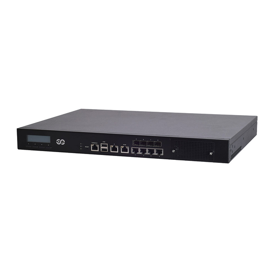
NCA-2510 User Manual The NCA-2510 is a 1U 19” rackmount network appliance with virtualization optimized design and Intel® Atom™ C3958, C3758 or C3558 CPU (codenamed Denverton). It offers up to 16 cores of processing prowess, 10G interface for SFP+, SR-IOV support, Intel® AES-NI and Intel® QuickAssist Technology, running at 20G, making it the ideal solution for vCPE, uCPE, SD-WAN and SD-Security on Intel®... -
Page 11: Chapter 1: Product Overview
Chapter 1: Product Overview SKU No. NCA-2510 A Intel C3958 16 Core with QAT + 5x GbE + 4x SFP+, 1x NIC (1x PCIex8/4x PCIex2) NCA-2510 B Intel C3758 8 Core with QAT + 5x GbE + 4x SFP+, 1x NIC (1x PCIex8/2x PCIex4) - Page 12 NCA-2510 User Manual Form Factor 1U 19" Rackmount Intel® Atom™ C3000 4/8/16 Cores Processor Options (Denverton) Platform CPU Socket Onboard Chipset Security Acceleration Intel® QuickAssist Technology BIOS AMI SPI Flash BIOS Technology DDR4 2400MHz, REG/ECC/UDIMM System Memory Max. Capacity 2/4/8/16/32GB...
- Page 13 Chapter 1: Product Overview NCA-2510A/B NCA-2510 C NCA-2510D Description With a Keypad System Power LED Indicators System Status HDD Activity Software reset Reset Button Console Port 1x Console port USB Port 2x USB 2.0 port MGMT Port 1x Management port...
- Page 14 NCA-2510 User Manual NCA-2510A/B/C/D Description Rear PCIe Expansion 1x PCIex8 Expansion slot (Riser card required) Console/VGA Port 2x reserved holes for Console/VGA cable Cooling Fans 2x swappable independent fan Power Button 1x ATX Power button Power Supply 1x 150W PSU...
-
Page 15: Chapter 2: Motherboard Information
Chapter 2: Motherboard Information The block diagram indicates how data flows among components on the motherboard. Please refer to the following figure for your motherboard’s layout design. - Page 16 NCA-2510 User Manual...
- Page 17 Chapter 2: Motherboard Information...
- Page 18 NCA-2510 User Manual The motherboard layout shows the connectors and jumpers on the board. Refer to the following picture as a reference of the pin assignments and the internal connectors.
- Page 19 Chapter 2: Motherboard Information ATX1: 24-Pin ATX Power Connector Description Description Description Description +3.3V -12V +3.3V +3.3V PSON- Ground Ground Ground Ground Ground Power Good Ground Ground +12V Stand-By 5V 3.3V Ground +12V ATX2: 4-pin Power Connector Description Description +12V +12V JSATA2 &...
- Page 20 NCA-2510 User Manual SW3: Reset Switch (reserved for debugging) Description Description FP_RST_SEL FP_RST_SEL SW1: PSON power switch (reserved for debugging) Description Description FP_SWIN_R FP_SWIN_R J21: Reset Description Description FP_SWIN_R CONN2: PSON power Description Description FP_SWIN_R JRESET1: Controls the software reset method of the Reset button on front panel.
- Page 21 Chapter 2: Motherboard Information JTPM1: TPM Description Description LPC_SERIRQ SOC_LPC_FRAME_N CLK_LPC_OUT SOC_LPC_LAD0 SOC_LPC_LAD1 P3V3_STBY SOC_LPC_LAD2 SOC_LPC_LAD3 P3V3_A CPLD_TPM_RESET_N Ground JLCM1: LCM Description Description Description Description LSTIN IOGND LPD1 LPD0 LAFD LINIT LPD5 LPD4 LPD3 LPD2 LPD7 LPD6 GPIO VCC3 VCC3 COMB2: COM PORT Description Description...
- Page 22 NCA-2510 User Manual JOPMA1: OPMA CON7 RSVD RSVD OPMA RSVD RSVD DVI_TX0_H LDRQ_L DVI_TX0_L LFRAME_L LAD0 DVI_TX1_H LCLKRUN_L DVI_TX1_L LAD1 LAD2 DVI_TX2_H LAD3 DVI_TX2_L SERIRQ LRST_L DVI_TXCLK_H LCLK DVI_TXCLK_L DVI-I RSVD DVI_DDC_DATA RSVD DVI_DDC_CLK RSVD I2C_PRIV0_SCL ANALOG_DDC_DATA I2C_PRIV0_SDA ANALOG_DDC_CLK I2C_IPMB_SCL...
- Page 23 Chapter 2: Motherboard Information JCMOS1: Clear CMOS Description Description Normal (Default) Clear CMOS Warning: After clearing CMOS or when PXE boot is enabled, the system boot-up time is doubled. JRTC1: RTC Description Description Normal (Default) Clear RTC JOPEN1: Case open Description Description CSOPEN_N...
- Page 24 NCA-2510 User Manual J9: Gen3 Bypass Firmware Update Description Description Normal (Default) Firmware Update J80PORT1: 80Port Debug Description Description LAD1 RST- LAD0 LRAME- POWER LAD3 LAD2 JPLD1: Altera CPLD Description Description JTAG_PLD_TCK JTAG_PLD_TDO P3V3_STBY JTAG_PLD_TMS JTAG_PLD_TDI...
- Page 25 Also, please wear ESD protection gloves when conducting the steps narrated in this chapter. 1. Loosen the two thumb screws from the rear panel of NCA-2510. 2. Gently pull the cover backward a bit.
- Page 26 NCA-2510 User Manual NCA-2510 is built with two 2.5” HDD/SSD slot drive bays. The following will discuss disk drive installation procedures based on their HDD/SSD designs. 1. Locate the 2.5” disk bay area in the chassis. 2. Loosen the only screw that secures the HDD tray.
- Page 27 Chapter 3: Hardware Setup 4. Take out the HDD tray. 5. Slide the disks into the tray. Make sure the disk connector faces the direction as the picture shows. SATA Contacts 6. To mount the disks onto the empty tray, secure them on the tray with two disk screws locked on each side of the disk.
- Page 28 NCA-2510 User Manual 8. Insert the other end of the SATA cable into the disk and connect the end of SATA power cable with the disk. The SATA connection between a disk and the system is now built up. Repeat Step 7~8 to establish the SATA connection of the other disk.
- Page 29 Chapter 3: Hardware Setup The NCA-2510 provides one OPMA slot for installing the IPMI card. Follow these procedures below for installing an IPMI card. 1. Locate the OPMA socket. 2. Align the notch of the card with the socket key in the slot.
- Page 30 NCA-2510 User Manual 5. Secure the card with a screw that comes with it. To remove the card, loosen the screw that secures it to the motherboard, push aside the two metal leaves that hold the card to release it from the socket before you can pull it out.
- Page 31 Chapter 3: Hardware Setup NCA-2510 comes with 1 NIC Ethernet module slot for network bandwidth expansion. Please follow the steps for installation. 1. Rotate the two lock-screws counterclockwise and loosen them. 2. Remove the door and locate the PCIe slot for module insertion.
- Page 32 NCA-2510 User Manual 4. Once the module is firmly seated, rotate clockwise and tighten the two lock-screws.
- Page 33 Chapter 3: Hardware Setup The motherboard provides one mSATA slot. Follow the procedures below for installing an mSATA card. 1. Locate the mSATA slot. 2. Align the notch of the module with the socket key in the slot. Socket Notch 3.
- Page 34 NCA-2510 User Manual The motherboard supports DDR4 registered DIMM memory for heavy-duty operations. Please follow the steps below to install the DIMM memory modules. 1. Locate the the DIMM slot. 2. Pull open the DIMM slot latches. 3. Align the notch of the DIMM module with the socket key in the slot.
- Page 35 To install a PCIe expansion card onto the motherboard with a Riser Card, please purchase the Riser Card kit from Lanner and have the PCIe expansion card you want to install ready. 1. Power off this system and remove the system cover.
- Page 36 NCA-2510 User Manual 4. Remove the original Riser Card. 5. Unbox your Riser Card Kit which contains a Riser Card, two Brackets and screws. Bracket B (for FH/FL size PCIe Expansion Riser Card Bracket A Card) 6. Assemble the Riser Card and Bracket A with four screws.
- Page 37 Chapter 3: Hardware Setup 8. From the inner side, insert the side of the PCIe Expansion card with the meshed metal slot cover into the chassis, with the holder stuck out from inside. Make sure the Grip is stuck out 9.
- Page 38 NCA-2510 User Manual There are two methods for installing this system into a rack: With Mounting Ear Brackets only This method is quick and easy by fixing this system to the front posts of the rack, but it also makes servicing the system more difficult.
- Page 39 Chapter 3: Hardware Setup 1. Check the accessory pack for the following items: 1x Screw Pack 2x Ear Brackets 2. Align the bracket to the side of the chassis and make sure the screw-holes are matched, and then secure the bracket onto the chassis with three provided screws.
- Page 40 NCA-2510 User Manual 1. Check the package contents of the Slide Rail Kit. The kit shall include the following items: 1x pack of M4X4L screws (for securing the Rail Brackets on the system) 1x pack of 7.1 Round Hole screws (for securing the system on...
- Page 41 Chapter 3: Hardware Setup 5. Align the bracket to the side of the chassis make sure screw-holes are matched, and then secure the bracket onto the chassis with three provided M4X4L screws. Align the screws with the holes indicated on the brackets and the screw holes on the side of the chassis.
- Page 42 NCA-2510 User Manual 9. For the rear rack installation, slide the rail to aim and engage the bolts on the rail’s rear end with the two available holes on the post, and the rail assembly will click into place. Click 10.
- Page 43 Chapter 3: Hardware Setup 12. While pushing in the system, also push and hold the Rail Lock tab on both brackets. Rail Lock Push the system all the way in until it stops. To remove the system from the rack, gently pull it outwards towards you while pushing the Release Tab on both sides of the brackets.
- Page 44 NCA-2510 User Manual To enter the BIOS setup utility, simply follow the steps below: 1. Boot up the system. 2. Press <Delete> during the boot-up if you connect a keyboard to this unit. But if you connect a PC to this unit through console USB/Serial connection, then press <Tab>.
- Page 45 Chapter 4: BIOS Setup Setup main page displays a description of BIOS information and project version information. You can also setup the System Time and System Date here. (The screenshots presented in section are for reference only)
- Page 46 NCA-2510 User Manual Use [←] [→] to select [Advanced] setup screen. Under this screen, you may use [↑] [↓] to select an item you want to configure.
- Page 47 Chapter 4: BIOS Setup This option allows you to configure parameters about BIOS support for the security device. Press <Enter> to access the submenu. The default is “Enabled”.
- Page 48 NCA-2510 User Manual This option allows you to configure parameters about Super IO Chip. Press <Enter> to access the submenu. Select Serial Port 1 Configuration or Serial Port 2 Configuration to enter sub setting screen. The default is “Enabled”.
- Page 49 Chapter 4: BIOS Setup This option allows you to configure Smart Fan properties and monitor the fan status.
- Page 50 NCA-2510 User Manual Enter “Smart Fan Control” to change fan mode. The default is “Smart Fan Mode”.
- Page 51 Chapter 4: BIOS Setup If with the case’s support, enabling this option will have the unit sound when someone opens the case of this unit, which is considered against your organization’s policy. The default is “Disabled”.
- Page 52 NCA-2510 User Manual This option allows you to configure Digital I/O pin properties. Select the desired pin and press <Enter> to modify. The default is “Output Low”.
- Page 53 Chapter 4: BIOS Setup This option allows you to enable or disable Watchdog Timer function. The default is “Disabled”.
- Page 54 NCA-2510 User Manual This option allows you to configure parameters about serial port console redirection. Press <Enter> to access the submenu. The default is “Enabled”.
- Page 55 Chapter 4: BIOS Setup Console Redirection Settings Select this item to enter the setting sub-menu. These settings specify how the host computer and the remote computer will exchange data. Both computers should have the same or compatible settings. Item Value Description VT100: ASCII char set.
- Page 56 NCA-2510 User Manual VT-UTF8 Combo Key Disabled Enable VT-UTF8 Combination Key Support for Support Enabled ANSI/VT100 terminals Disabled With this mode enabled only text will be sent. Recorder Mode Enabled This is to capture Terminal data. VT100 LINUX XTERM86 Putty KeyPad Select FunctionKey and KeyPad on Putty.
- Page 57 Chapter 4: BIOS Setup This option allows you to configure parameters to be programmed into PCI Latency Timer Register.
- Page 58 NCA-2510 User Manual PCI Express Settings This option allows you to enable or disable PCI Express Device Relaxed Ordering.
- Page 59 Chapter 4: BIOS Setup PCI Express GEN 2 Settings This option allows you to enable or disable PCI ExpressGEN2 related setting.
- Page 60 NCA-2510 User Manual This option allows you to enable or disable UEFI Network Stack. The default is “Disabled “.
- Page 61 Chapter 4: BIOS Setup This option allows you to enable or disable ROM execution settings. Item Value Description Disabled CSM Support Enables or disables CSM Support Enabled Do Not Launch Controls the execution of UEFI and Network UEFI Legacy PXE OpROM Legacy Do Not Launch Controls the execution of UEFI and...
- Page 62 NCA-2510 User Manual This option allows you to change USB configuration parameters. Legacy USB Support Item Value Description Enables Legacy USB support. “Auto“ disables legacy support if no USB Enabled devices are connected. “Disabled“ will Legacy USB Support Disabled keep USB devices available only for EFI Auto applications.
- Page 63 Chapter 4: BIOS Setup 1 sec Set USB time-out value (1, 5, 10 or 20 5 sec USB transfer time-out seconds) for Control, Bulk and Interrupt 10 sec transfers. The default is “20 sec “. 20 sec 10 sec Set USB mass storage device Start Unit 20 sec Device reset time-out: command time-out (10, 20, 30 or 40...
- Page 64 NCA-2510 User Manual Use [←] / [→] to select the Chipset menu item from the BIOS setup screen to enter the IntelRCSetup Setup screen. Users can select any of the items in the left frame of the screen.
- Page 65 Chapter 4: BIOS Setup Item Value Description Enables or disables EIST. GV3 and TM1 must be enabled for TM2 to be available. Disable EIST(GV3) GV3 must be enabled for Turbo. Auto - Enabled Enable for B0 CPU stepping, all others disabled, change setting to override.
- Page 66 NCA-2510 User Manual...
- Page 67 Chapter 4: BIOS Setup This option enables or disables fast boot which skips memory training and attempts to boot using last known good configuration. The default is “Enabled”.
- Page 68 NCA-2510 User Manual This option allows you to configure SATA Controller properties. SATA Configuration Enables/Disables SATA Controller if supported by current CPU SKU. The default is “Enabled”. Enabling the SATA controller, you can respectively modify the JSATA1, JSATA1 and mSATA...
- Page 69 Chapter 4: BIOS Setup Use [←] [→] to select Security setup screen. Under this screen, you may use [↑] [↓] to select an item you would like to configure. Administrator Password & User Password Item Description Administrator If ONLY the Administrator's password is set, then this only limits access to Password Setup and is only asked for when entering Setup.
- Page 70 NCA-2510 User Manual Secure Boot Enter Secure Boot page for more related settings. Item Value Description Secure Boot is activated when Platform Key(PK) is enrolled, System mode is Disabled Attempt Secure Boot User/Deployed, and CSM function is Enabled disabled Secure Boot mode selector:...
-
Page 71: Key Management
Chapter 4: BIOS Setup Key Management Item Value Description Allows you to provision factory default Provision Factory Disabled Secure Boot keys when System is in Defaults Enabled Setup Mode. Install Factory Default Forces System to enter User Mode - None keys install all Factory Default keys Allows the image to run in Secure Boot... - Page 72 NCA-2510 User Manual Select the Boot menu item from the BIOS setup screen to enter the Boot Setup screen. Description Item Value Disabled Quiet Boot Enables or disables Quiet Boot option. Enabled LEGACY Boot mode select UEFI Select boot mode.
- Page 73 Select the Save and Exit menu item from the BIOS setup screen to enter the Save and Exit Setup screen. Users can select any of the items in the left frame of the screen. Save Changes and Exit When you have completed the system configuration, select this option to save the changes and Exit from BIOS Setup, so the new system configuration parameters can take effect.
- Page 74 NCA-2510 User Manual The status explanations of LED indicators on Front Panel are as follows: System Power System Status HDD Activity System Power Solid Green The system is powered on The system is powered off System Status This LED indicator is programmable. You could program it to display the operating status with the...
- Page 75 Appendix A: LED Indicator Explanations Link Activity Speed Link Activity Solid Green Link has been established and there is no activity on this port Blinking Green Link has been established and there is activity on this port No link has been established Speed Solid Green Operating as a 10-Gigabit connection...
-
Page 76: Watchdog Timer
-swt xxx (Set Watchdog Timer 1-255 seconds and start to count-down) wd_tst -stop (Stop Watchdog Timer) For a reference utility that contains sample code for watchdog function programming, please visit http://www.lannerinc.com/support/download-center/drivers, enter the product category and download the utility package of NCA-2510. -
Page 77: Appendix C: Setting Up Console Redirections
Appendix C: Setting up Console Redirections Console redirection lets you monitor and configure a system from a remote terminal computer by re-directing keyboard input and text output through the serial port. The following steps illustrate how to use this feature. The BIOS of the system allows the redirection of the console I/O to a serial port. With this configured, you can remotely access the entire boot sequence through a console port. - Page 78 Bypass Gen 3 employs a programming method to control the bypass function by software. There are typically two types of communication status for the bypass function, one is “Normal“ and another is “Bypass“ status. Furthermore, the Lanner Bypass software is capable of controlling the bypass status in the following 3 instances.
- Page 79 To install the Intel® LAN controller base driver for the Red Hat® and Linux operating system, please visit http://www.lannerinc.com/support/download-center/drivers, enter the product category and download the utility package of NCA-2510. For the latest driver update, please visit Intel® download center at https://downloadcenter.intel.com/, use the keyword search or the filter to access the driver’s product page, and then download the latest controller...
- Page 80 NCA-2510 User Manual 1. All products are under warranty against defects in materials and workmanship for a period of one year from the date of purchase. 2. The buyer will bear the return freight charges for goods returned for repair within the warranty period;...
-
Page 81: Appendix F: Terms And Conditions
Appendix F: Terms and Conditions When requesting RMA service, please fill out the following form. Without this form enclosed, your RMA cannot be processed.
Need help?
Do you have a question about the NCA-2510 and is the answer not in the manual?
Questions and answers