Table of Contents
Advertisement
Advertisement
Table of Contents

Related Manuals for Lanner NCA-4010 Series


Summary of Contents for Lanner NCA-4010 Series
-
Page 1: User Manual
Network Computing Platforms NCA-4010 User Manual Rev 1.5 Sep 11 , 2018... -
Page 2: Revision History
Modified Jumper Setting and Connector Pin-out 2018/09/11 Added VCCI Class A Statement This document contains proprietary information of Lanner Electronics Inc. –and is not to be disclosed or used except in accordance with applicable agreements. Copyright © 2018. All Rights Reserved. - Page 3 Network Computing Platforms Online Resources The listed websites are links to the on-line product information and technical support. Resource Website Lanner www.lannerinc.com Product www.lannerinc.com/support/download-center Resources http://eRMA.lannerinc.com Acknowledgement Intel, Pentium and Celeron are registered trademarks of Intel Corp. Microsoft Windows and MS-DOS are registered trademarks of Microsoft Corp.
- Page 4 Network Computing Platforms not installed and used in accordance with the instruction manual, may cause harmful interference to radio communications. Operation of this equipment in a residential area is likely to cause harmful interference in which case users will be required to correct the interference at their own expense.
- Page 5 Network Computing Platforms complete or intermittent failures. Be sure to follow ESD-prevention procedures when removing and replacing components to avoid these problems. Wear an ESD-preventive wrist strap, ensuring that it makes good skin contact. If no wrist strap is available, ground yourself by touching the metal part of the chassis. ...
- Page 6 Network Computing Platforms Ne considerez jamais que l’alimentation est coupee d’un circuit, verifiez toujours le circuit. Cet appareil genere, utilise et emet une energie radiofrequence et, s’il n’est pas installe et utilise conformement aux instructions des fournisseurs de composants sans fil, il risque de provoquer des interferences dans les communications radio.
- Page 7 Network Computing Platforms Un cable de mise a la terre est requis et la zone reliant les sections du conducteur doit faire plus de 4 mm2 ou 10 AWG. Procédure de mise à la terre pour source d’alimentation CC Procédure de mise à la terre pour source d’alimentation CC •...
-
Page 8: Table Of Contents
Network Computing Platforms Table of Contents Chapter 1: Introduction ....................10 System Specification .................... 10 Ordering Information ................... 12 Package Contents ....................12 Optional Accessories .................... 12 Chapter 2: System Overview ..................13 Mechanical Drawing .................... 13 Block Diagram ..................... 14 Front I/Os ...................... - Page 9 Network Computing Platforms PCH State after G3: ..................90 Security ........................ 91 Boot ........................92 Save & Exit ......................95 Appendix A: Programming Watchdog Timer ............101 Appendix B: Setting up Console Redirection ............102 Appendix C: Programming Generation 3 LAN Bypass ..........103 Appendix D: Programming the LCM ................
-
Page 10: Chapter 1: Introduction
8/16 x port RJ45 GBE, 2 port x 10G SFP+ (model A only), 1 x Lanner standard NIC modules, 1 x 3.5” / 2 x 2.5” SATA disk drive kit, 1 x OPMA socket for IPMI and 1 x mSATA socket. For network reliability, NCA-4010 supports 3 or 7 pairs of LAN bypass depending on the SKU selection. - Page 11 AC 90 to 264V@47 to 63Hz Power Power supply 220W single PSU Certifications CE/FCC Class A, RoHS *The remake about the IPMI support requires changes in BOM and it is based on custom projects. For requirements about IPMI support, please consult with Lanner representatives.
-
Page 12: Ordering Information
Network Computing Platforms Ordering Information NCA-4010A 1U x86 Rackmount Network Appliance based on Intel Xeon D-1548 Processor (codename Broadwell-DE) SoC, 16 GbE RJ45 with 2 SFP+ 10GbE ports, 1 NIC Module Slot and 7 pairs of LAN bypass NCA-4010B 1U x86 Rackmount Network Appliance based on Intel Xeon D-1518 Processor (codename Broadwell-DE) SoC, 8 GbE RJ45 ports, 1 NIC Module Slot and 3 pairs of LAN bypass NCA-4010C... -
Page 13: Chapter 2: System Overview
Network Computing Platforms Chapter 2: System Overview Mechanical Drawing Unit: mm... -
Page 14: Block Diagram
Network Computing Platforms Block Diagram Note: TPM is optional The diagram is based on 8 x RJ-45 GbE design. The number of LAN ports is 16 for model-A. The 2 x 10G SFP+ ports are only available in model A. -
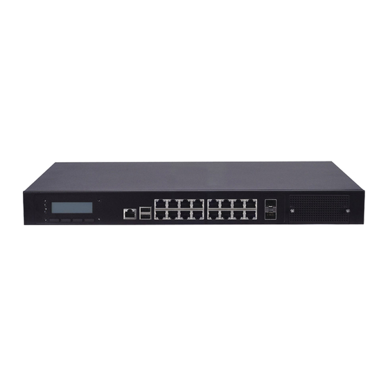
Page 15: Front I/Os
Network Computing Platforms Front I/Os LED Indicators POWER/STATUS/HDD Power: status about power supply Status: programmable status LED signals for system activities HDD: status about storage devices, such as HDD or SSD LCM with 4 x keypads Console 1 x RJ-45 console port 2 x USB 2.0 Type-A ports in double stacked form 8 or 16 x RJ-45 GbE ports depending on the model types... -
Page 16: Rear I/Os
Network Computing Platforms Rear I/Os PCIe 1 x PCIe expansion slot (optional) Expansion Fans 2 x cooling fans Power switch 1 x power on/off switch power jack 1 x power jack for connection with power adapter... -
Page 17: Chapter 3: Board Layout
Network Computing Platforms Chapter 3: Board Layout Jumpers and Connectors on the Motherboard JLCM1 SATAPWR1/2 ATX1 COMB1 USB1 JDDR1/2 ATX2 JSATA1/2 FAN1/2 JVGA1 COMA1 J1/2 JMSATA1 JPCIESLOT1 J9/10/11 JOPMA1 JBIOS1... - Page 18 Network Computing Platforms Jumpers and Connectors on the Motherboard (cont’d) JSPIROM1 JTPM1 JCMOS1...
-
Page 19: Jumper Setting And Connector Pin-Out
Network Computing Platforms Jumper Setting and Connector Pin-out ATX1: 24-pin ATX power connector DESCRIPTION DESCRIPTION 3.3V 3.3V 3.3V -12V PSON# ATXPWGD 5VSB 3.3V... - Page 20 Network Computing Platforms ATX2: 4-pin ATX power connector DESCRIPTION COMA1: internal serial COM pin header DESCRIPTION DESCRIPTION NDCD2- NDSR2- NRXD2 NRTS2- NTXD2 NCTS2- NDTR2- NRI2-...
- Page 21 Network Computing Platforms CONN2: 2-pin power connector for the power button on the panel DESCRIPTION POWER ON# FAN1/2: 2 x 5-pin cooling fan connectors DESCRIPTION CPUFANOUTPWM CPUFANIN...
- Page 22 Network Computing Platforms J1/2 : 2 x 50-pin I/O board connectors. NCA-4010 can be accompanied by I/O board NM-4010IG401. DESCRIPTION DESCRIPTION P3V3 P12V P3V3 P12V P3V3 PCH_SLOT3_A8 PCIESLOT3_I350A_RST# P3V3 PHY_WAKE# SLT3A_SCLK2 CLK100_PCIE_SOLT3_1P SLT3A_SDAT2 CLK100_PCIE_SOLT3_1N IO_LAN12GND IO_LAN34GND IO_P0_S0_1 IO_P1_S0_1...
- Page 23 Network Computing Platforms IO_P0_S0_2 IO_P1_S0_2 PCIE_CTX_C_SLOT3RX_P0 PCIE_SLOT3TX_C_CRX_P0 PCIE_CTX_C_SLOT3RX_N0 PCIE_SLOT3TX_C_CRX_N0 PCIE_CTX_C_SLOT3RX_P1 PCIE_SLOT3TX_C_CRX_P1 PCIE_CTX_C_SLOT3RX_N1 PCIE_SLOT3TX_C_CRX_N1 PCIE_CTX_C_SLOT3RX_P2 PCIE_SLOT3TX_C_CRX_P2 PCIE_CTX_C_SLOT3RX_N2 PCIE_SLOT3TX_C_CRX_N2 PCIE_CTX_C_SLOT3RX_P3 PCIE_SLOT3TX_C_CRX_P3 PCIE_CTX_C_SLOT3RX_N3 PCIE_SLOT3TX_C_CRX_N3 J2 : DESCRIPTION DESCRIPTION P3V3 P12V P3V3 P12V P3V3 PCH_SLOT3_A8 PCIESLOT3_I350B_RST# P3V3 PHY_WAKE# SLT3B_SCLK3 CLK100_PCIE_SOLT3_2P SLT3B_SDAT3 CLK100_PCIE_SOLT3_2N IO_LAN56GND IO_LAN78GND...
- Page 24 Network Computing Platforms IO_P2_S0_1 IO_P3_S0_1 IO_P2_S0_2 IO_P3_S0_2 PCIE_CTX_C_SLOT3RX_P4 PCIE_SLOT3TX_C_CRX_P4 PCIE_CTX_C_SLOT3RX_N4 PCIE_SLOT3TX_C_CRX_N4 PCIE_CTX_C_SLOT3RX_P5 PCIE_SLOT3TX_C_CRX_P5 PCIE_CTX_C_SLOT3RX_N5 PCIE_SLOT3TX_C_CRX_N5 PCIE_CTX_C_SLOT3RX_P6 PCIE_SLOT3TX_C_CRX_P6 PCIE_CTX_C_SLOT3RX_N6 PCIE_SLOT3TX_C_CRX_N6 PCIE_CTX_C_SLOT3RX_P7 PCIE_SLOT3TX_C_CRX_P7 PCIE_CTX_C_SLOT3RX_N7 PCIE_SLOT3TX_C_CRX_N7 J3 : I/O board (NM-4010IG401) ARM Programming Selection 0(2-3) : Enable 1(1-2) : Disable (default) DESCRIPTION P3V3 IO_PIO0_1...
- Page 25 Network Computing Platforms J4: Fresh I/O board (NM-4010IG401) BYPASS DESCRIPTION DESCRIPTION IO_NXP_RXD IO_NXP_RTS_N IO_NXP_TXD IO_NXP_CTS_N J7 : Fresh main board BYPASS DESCRIPTION DESCRIPTION NXP_RXD NXP_RTS_N NXP_TXD NXP_CTS_N...
- Page 26 Network Computing Platforms J8 : Main board ARM Programming Selection 0(2-3) : Enable 1(1-2) : Disable (default) DESCRIPTION P3V3 CPLD_LED3 J9/J10: PHY I2C Source Selection (2-3) : From Tool (1-2) : From CPU (default)
- Page 27 Network Computing Platforms DESCRIPTION PHY_I2C_SDA PHY_I2C_SDA_JUMP PHY_I2C_SDA_TOOL DESCRIPTION PHY_I2C_SCL PHY_I2C_SCL_JUMP PHY_I2C_SCL_TOOL J11: PHY I2C debug pin header DESCRIPTION PHY_I2C_SDA_TOOL PHY_I2C_SCL_TOOL...
- Page 28 Network Computing Platforms J80PORT1 : Debug Port DESCRIPTION DESCRIPTION CLK_33M_PORT80 LPC_LAD1_R 80PORT_RST# LPC_LAD0_R LPC_FRAME#_P80 P3V3 LPC_LAD3_P80 LPC_LAD2_P80 JBIOS1: PHY fresh BIOS DESCRIPTION SFPP0_EEPROM_I2C_SDA SFFP0_EEPROM_I2C_SCL JCMOS1 : 1-2 : NORMAL 2-3 : CLEAR CMOS...
- Page 29 Network Computing Platforms DESCRIPTION VCC_RTC PCH_RTCRST# JCPLD1: Fresh CPLD (Complex Programmable Logic Device) DESCRIPTION P3V3_SB DUAL_SPI_TDO JLCM1: LCM module connector J_CPLD_TDI CPLD_TMS CPLD_TCK...
- Page 30 Network Computing Platforms DESCRIPTION DESCRIPTION P_SLIN_N P_AFD_N P_INIT_N LPD1 LPD0 LPD3 LPD2 LPD5 LPD4 LPD7 LPD6 LCD- KPA1 KPA2 KPA3 KPA4 LCM_RST CTR_GRN CTR_YEW HDD_LED#...
- Page 31 Network Computing Platforms JMSATA1: mSATA module DESCRIPTION DESCRIPTION P3V3...
- Page 32 Network Computing Platforms SATA_DTX_CRX_P1 P3V3 SATA_DTX_CRX_N1 SATA_CTX_C_DRX_N1 SATA_CTX_C_DRX_P1 P3V3 P3V3 P3V3...
- Page 33 Network Computing Platforms JRESET1 : Select front-panel reset option Hardware Reset Software Reset (Default) DESCRIPTION BTN_SYS_RESET# FP_RESET# SW_RST_GP5# JSATA1/JSATA2 : SATA connectors for storage devices...
- Page 34 Network Computing Platforms JSATA1 DESCRIPTION SATA_CTX_C_DRX_P2 SATA_CTX_C_DRX_N2 SATA_DTX_CRX_N2 SATA_DTX_CRX_P2 JSATA2 DESCRIPTION SATA_CTX_C_DRX_P3 SATA_CTX_C_DRX_N3 SATA_DTX_CRX_N3 SATA_DTX_CRX_P3 JSPIROM1: Fresh BIOS...
- Page 35 Network Computing Platforms DESCRIPTION DESCRIPTION SPI_HD1# J_SPI2_CS0#_DUAL J_SPI1_CS0#_DUAL P3V3_SB SPI_MISO_DUAL SPI_HOLD0_L SPI_CLK_DUAL SPI_MOSI_DUAL JTPM1: TPM module pin header (optional) DESCRIPTION DESCRIPTION LPC_SERIRQ LPC_FRAME# LPC_LAD0 CLK_33M_PORT80 LPC_LAD1 P3V3_SB LPC_LAD2 LPC_LAD3 P3V3 PLT_RST#...
- Page 36 Network Computing Platforms JVGA1: VGA internal connector DESCRIPTION DESCRIPTION DAC_RO DAC_GO DAC_BO HSYNC_O VSYNC_O DDC_DATA DDC_CLK SATAPWR1/SATAPWR2: SATA 4-pin POWER connectors DESCRIPTION P12V...
-
Page 37: Chapter 4: Hardware Setup
Network Computing Platforms Chapter 4: Hardware Setup Preparing the Hardware Installation To access some components and perform certain service procedures, you must perform the following procedures first. WARNING: To reduce the risk of personal injury, electric shock, or damage to the equipment, please remove all power sources. -
Page 38: About The Cpu, Heatsink And Heat-Radiation Bracket
Network Computing Platforms 4. Lift the top compartment. About the CPU, Heatsink and Heat-radiation Bracket Since the CPU is soldered onboard, the heatsink and the heat radiation brackets are pre-installed before shipment. In normal circumstances, no installation nor replacement is required. -
Page 39: Installing The System Memory
Network Computing Platforms Installing the System Memory The motherboard supports DDR4 RDIMM/ECC/UDIMM up to 2,400MHz memory at max. 16GB per socket. Please follow the steps below to install the DIMM memory modules. 1. Power off the system and locate the DDR DIMM slot. 2. -
Page 40: Installing Disk Drives
Network Computing Platforms Installing Disk Drives The system supports 1 x 3.5” or 2 x 2.5” SATA HDDs or SSDs as data storage. Please follow the steps below for installation. (Note: the following steps are based on 2 x 2.5” SATA disk drives installation). - Page 41 Network Computing Platforms 3. Take the tray out and prepare to install a SATA 2.5” disk drive. 4. Place the disk drive as shown in the image below. Apply 2 screws for each side of the disk drive. SATA connector this way 5.
- Page 42 Network Computing Platforms 6. Establish SATA cable connection between the disk drive and the motherboard. Please apply 15+7 SATA cable to the drive while using SATA 7-pin connector and SATA 4-pin connector for the motherboard.
-
Page 43: Installing A Msata Module
Network Computing Platforms Installing a mSATA Module The motherboard provides one mSATA slot. Follow the procedures below for installing a mSATA card. 1. Locate the mSATA socket. 2. Insert a mSATA module as shown in the image below card. 3. Press the module down and apply two screws to secure it. -
Page 44: Installing An Ipmi Card (Project-Based)
Network Computing Platforms Installing an IPMI Card (Project-based) The motherboard provides one OPMA socket which is used to install an IPMI card. Please follow the steps below for instructions. 1. Locate the OPMA socket. 2. Insert an IPMI card into the socket and then press it down. - Page 45 Network Computing Platforms 3. Apply a screw to secure the IPMI card. Notes: The remake about the IPMI support requires changes in BOM and it is based on custom projects. For requirements about IPMI support, please consult with Lanner representatives.
-
Page 46: Replacing Cooling Fans
Network Computing Platforms Replacing Cooling Fans NCA-4010 supports 2 cooling fans. To replace a worn-down fan, please follow the steps below. 1. Remove the screws circled below. 2. Apply some force and pull the fan out of its original place, as shown in the image below. 3. -
Page 47: Installing Ethernet Nic Modules
Notes: For information about compatible modules, please refer to the “Ordering Information” and “Optional Accessories” sections, or contact Lanner for more details. 1. Remove the two captive screws on the bezel of the module slot and open the bezel. - Page 48 Network Computing Platforms 3. Slide your Ethernet NIC module into the space, until it is firmly attached. 4. Secure the module with two captive screws on the bezel.
-
Page 49: Rackmount Installation
Network Computing Platforms Rackmount Installation Attach the Inner Rails 1. Check the package contents. 2 x 438mm Slide-Rails 1 x pack of screws . Turn a slide rail upside down and release the inner bracket. Slide the inner bracket all the way up to end of the slide-rail assembly. You may hear a “click”... - Page 50 Network Computing Platforms Release the inner bracket as shown below. 7. Align the inner bracket to the side of the chassis and make sure the screw-holes are matched. Then secure the bracket onto the chassis with provided screws. 8. Repeat Steps 2 to 7 for another slide-rail and attach its inner bracket onto another side of the chassis.
- Page 51 Network Computing Platforms Click 2. For the rear rack installation, also aim at 3 available holes and click the slide-rail assembly onto the rear rack. Click 3. Repeat Step 1 and 2 for another slide-rail assembly in order to install in onto the rack.
- Page 52 Network Computing Platforms...
- Page 53 Network Computing Platforms Installing NCA-4010 onto the Rack Reminder: it is strongly recommended to carry out this procedure with two or three persons. 1. Hold the applicable model with its front facing you, lift the chassis and gently insert the model by aligning with the slide-rail assemblies, as shown in the image below.
- Page 54 Network Computing Platforms 2. Simultaneously push the release tabs on both sides in the arrow of direction below, while pushing the appliance into the end of the rack. Caution: the appliance will be locked during the half way of sliding-in if the release tabs are not pushed.
- Page 55 Network Computing Platforms 3. Slide the appliance all the way into the assembly until it reaches its end. 4. To slide the appliance out, gently pull it outwards. Then, press the slide-rail locks on both side and slide the appliance out.
-
Page 56: Chapter 5: Bios Setup
Network Computing Platforms Chapter 5: BIOS Setup To enter the BIOS setup utility, simply follow the steps below: 1. Boot up the system. 2. Press <Delete> during the boot-up. Your system should be running POST (Power-On-Self-Test) upon booting up. 3. Then you will be directed to the BIOS main screen. 4. -
Page 57: Main
Network Computing Platforms Main The [Main] is the first setup screen when you enter BIOS. The [Main] displays general system and BIOS information and you may configure the “System Language”, “System Date”, and “System Time”. BIOS Information BIOS Vendor: displays BIOS vendor information Core Version: displays the BIOS core version Compliancy: displays the BIOS compliancy Project Version: displays BIOS project version... -
Page 58: Advanced
Network Computing Platforms Advanced Use [<--] / [-->] to select [Advanced] setup screen. Under this screen, you may use [↑] [↓] to select an item you wish to configure. PXE Function This option allows users to set PXE (Preboot Execution Environment) functions. Users may enable LAN2 to LANX depending on their applications. -
Page 59: Trusted Computing
Network Computing Platforms Trusted Computing This option enables users to configure “Trusted Computing” settings. Please be noted that TPM module shall have been installed first in order to make any configuration. Security Device Support: this enables or disables BIOS support for security device. Please be noted that the operating system will not show Security Device. -
Page 60: Nct6776 Super Io Configuration
Network Computing Platforms NCT6776 Super IO Configuration Press “Enter” to access configuration sub-menu for super IO chip (NCT6776) parameters. You may access settings for Serial Port 1 or 2 or the Parallel port. NCT6776 Super IO Configuration - Serial Port 1 Configuration The super IO chip for this model is NCT6776. - Page 61 Network Computing Platforms Press “Enter” to enable or disable the Serial Port 1 (COMA). Device setting is fixed as default. NCT6776 Super IO Configuration - Serial Port 2 Configuration Once Serial Port 2 is accessed, you may press “Enter” to enable or disable the Serial Port 2 (COM).
- Page 62 Network Computing Platforms Parallel Port Configuration This option allows you to set parameters for parallel port (LPT/LPTE).
-
Page 63: Nct76776 Hw Monitor
Network Computing Platforms Once Parallel Port is accessed, you may press “Enter” to enable or disable the Parallel Port. Device setting is fixed as default. NCT76776 HW Monitor This option allows you to view hardware health status. -
Page 64: Serial Port Console Redirection
Network Computing Platforms Serial Port Console Redirection This option allows you to configure parameters about serial port console redirection. Press “Enter” to access the submenu. - Page 65 Network Computing Platforms select “Enabled” or “Disable” for COM port console redirection. Console Redirection: The default is “Enabled”.
-
Page 66: Com Console Redirection Settings
Network Computing Platforms select this item to enter the setting sub-menu. Console Redirection Settings: COM Console Redirection Settings the emulation configuration. Select “VT100”, “VT100+”, “VT-UTF8” or Terminal Type: “ANSI”. VT100: ASCII character set VT100+: extends VT100 to support color function keys VT-UTF8: uses UTF8 encoding to map Unicode characters onto 1 or more ANSI: Extended ASCII character set... - Page 67 Network Computing Platforms select “9600”, “19200”, “38400”, “57600”, or “115200” for bits per Bits per second: second. The Bps will determine serial port transmission speed. The speed must be matched on the other side. Long or noisy lines may require lower speeds select the value for data bits.
- Page 68 Network Computing Platforms a parity bit can be sent with the data bits to detect some transmission errors. Parity Bits: Select “None”, “Even”, “Odd”, “Mark” or “Space”. : stop bits indicate the end of a serial data packet. The standard is 1 stop bit. Stop Bits Communication with slow devices may require more than 1.
- Page 69 Network Computing Platforms flow control can prevent data loss from buffer overflow. When sending data, if Flow Control: the receiving buffers are full, a “stop” signal can be sent to stop the data flow. You may select “None” or “Hardware RTS/CTS”, depending on the circumstances. this option enables/disables VT-UTF8 combination key VT-UTF8 Combo Key Support: support for ANSI/VT100 terminals.
- Page 70 Network Computing Platforms : on this mode, when “Enabled”, only text will be sent. This is to capture Recorder Mode terminal data. select “Enable” or “Disable” for extended terminal resolution. Resolution 100 x 31:...
- Page 71 Network Computing Platforms select “80x24” or “80x25”. The default for this case Legacy OS Redirection Resolution: is “80x24”. select Function Key and Key Pad on Putty. You may select “VT100”, Putty KeyPad: “LINUX”, “XTERMR6”, “SCO”, “ESCN”, or “VT400”.
-
Page 72: Usb Configuration
Network Computing Platforms The settings specify if BootLoader is selected than Legacy Redirection After BIOS POST: console redirection is disabled before booting to Legacy OS. Default value is “Always Enable” which means Legacy OS console redirection is always enabled after BIOS. USB Configuration This option allows you to configure USB device Settings. - Page 73 Network Computing Platforms displays USB module version USB Module Version: displays USB devices USB Devices: displays USB controller information USB Controllers: this function enables or disables legacy USB support. Auto option Legacy USB Support: disables legacy support if no USB devices are connected. Disable option will keep USB devices available only for EFI applications.
- Page 74 Network Computing Platforms this option allows you to enable or disable USB mass storage USB Mass Storage Driv: driver. The default is “Enabled”. this option enables I/O port 60h/64h emulation support. This should Port 60/64 Emulation: be enabled for the complete USB keyboard legacy support for non-USB aware operating systems.
- Page 75 Network Computing Platforms set USB time-out value (1, 5, 10 or 20 seconds) for Control, Bulk USB transfer time-out: and Interrupt transfers. set USB mass storage device Start Unit command time-out (10, 20, Device reset time-out: 30 or 40 seconds).
- Page 76 Network Computing Platforms set the maximum time the device will take before it properly Device power-up delay: reports itself to the Host Controller. “Auto” uses default value. For example, it is 100ms as a root port.
-
Page 77: Intelrcsetup
Network Computing Platforms IntelRCSetup Use [<--] / [-->] to select [IntelRCSetup] setup screen. Under this screen, you may use [↑] [↓] to select Processor Configuration , Memory Configuration , PCH Configuration or PCH State after G3 to change the settings of CPU, memory and PCH functions. displays and provides options to change processor settings. -
Page 78: Memory Configuration
Network Computing Platforms enables or disables AES-NI (Advanced Encryption Standard - New Instruction) AES-NI: support. Memory Configuration Memory Configuration displays and provides options to change the memory settings. You may press Enter to access the sub-menu. - Page 79 Network Computing Platforms this option displays memory topology with DIMM population information. Memory Topology: Each socket has 2 nodes/iMC’s (numbered from 0 to 7). Each node supports up to 2 channels (0 and 1).
-
Page 80: Pch Configuration
Network Computing Platforms PCH Configuration This function allows users to view and configure PCH settings. Press Enter to access the sub-menu. PCH SATA Configuration Press Enter to access items for SATA devices and settings. - Page 81 Network Computing Platforms enables or disables SATA controller SATA Controller: this item identifies whether the SATA port is connected to a SSD and Configure SATA as: HDD. Select IDE, AHCI or RAID. The default is “AHCI”.
- Page 82 Network Computing Platforms displays status of mSATA storage device mSATA: displays information of Software Preserve Software Preserve: enable or disable mSATA socket mSATA: designates this port as hot pluggable Hot Plug:...
- Page 83 Network Computing Platforms configures the port as External SATA (eSATA) Configure as eSATA: if enabled for any of ports, Staggered Spin Up will be performed and only Spin Up Device: the drives which have this option enabled will spin up at boot. Otherwise all drives spin up at boot.
- Page 84 Network Computing Platforms identifies the SATA port is connected to SSD (Solid State Drive) or SATA Device Type: HDD (Hard Disk Drive). enable or disable the SATA port SATA1:...
- Page 85 Network Computing Platforms enable or disable the SATA port Device Sleep. Board rework for LP is SATA1 DevSlp: needed before enabling this power-saving function. designates this port as hot pluggable Hot Plug:...
- Page 86 Network Computing Platforms configures the port as External SATA (eSATA) Configure as eSATA: if enabled for any of ports, Staggered Spin Up will be performed and only Spin Up Device: the drives which have this option enabled will spin up at boot. Otherwise all drives spin up at boot.
- Page 87 Network Computing Platforms identifies the SATA port is connected to SSD (Solid State Drive) or SATA Device Type: HDD (Hard Disk Drive). enable or disable the SATA port SATA2:...
- Page 88 Network Computing Platforms designates this port as hot pluggable Hot Plug: configures the port as External SATA (eSATA) Configure as eSATA:...
- Page 89 Network Computing Platforms if enabled for any of ports, Staggered Spin Up will be performed and only Spin Up Device: the drives which have this option enabled will spin up at boot. Otherwise all drives spin up at boot. identifies the SATA port is connected to SSD (Solid State Drive) or SATA Device Type: HDD (Hard Disk Drive).
-
Page 90: Pch State After G3
Network Computing Platforms PCH State after G3: Select S0/S5 for ACPI state after a G3. The choices are “S0”, “S5” or “Last State”. -
Page 91: Security
Network Computing Platforms Security Use [<--] / [-->] to select [Security] setup screen. Under this screen, you may use [↑] [↓] to select an item you want to configure. set administrator password. Once set, then this only limits Administrator Password: access to Setup and is only asked for when entering Setup. -
Page 92: Boot
Network Computing Platforms Boot Use [<--] / [-->] to select [Boot] setup screen. Under this screen, you may use [↑] [↓] to select an item you want to configure. Boot Configuration number of seconds to wait for setup activation key. “65535 Setup Prompt Timeout: (0xFFFF)”... - Page 93 Network Computing Platforms this option allows you to enable or disable “Quiet Boot”. The default is Quiet Boot: “Disabled” based on Intel’s server environment setting. Boot Option Priorities set devices as boot option #1/2 for the system boot order Boot Option #1/2:...
- Page 94 Network Computing Platforms set the order of the legacy devices in this group USB Device BBS Priorities:...
-
Page 95: Save & Exit
Network Computing Platforms Save & Exit Use [<--] / [-->] to select [Save & Exit] setup screen. Under this screen, you may use [↑] [↓] to select an item you want to configure. exit system setup after saving the configuration changes Save Changes and Exit: exit system setup without saving the configuration changes Discard Changes and Exit:... - Page 96 Network Computing Platforms exit system setup after saving the configuration changes Save Changes and Exit: exit system setup without saving the configuration changes Discard Changes and Exit:...
- Page 97 Network Computing Platforms reset the system after saving the configuration changes Save Changes and Reset: reset the system without saving the configuration changes Discard Changes and Reset:...
- Page 98 Network Computing Platforms save the configuration changes done so far Save Changes: discard all the configuration changes Discard Changes:...
- Page 99 Network Computing Platforms restore/load factory default setting for all setup parameters. Restore Defaults: save changes done so far as user default Save as User Defaults:...
- Page 100 Network Computing Platforms restore the user default Restore User Defaults:...
-
Page 101: Appendix A: Programming Watchdog Timer
Network Computing Platforms Appendix A: Programming Watchdog Timer A watchdog timer is a piece of hardware that can be used to automatically detect system anomalies and reset the processor in case there are any problems. Generally speaking, a watchdog timer is based on a counter that counts down from an initial value to zero. The software selects the counter’s initial value and periodically restarts it. -
Page 102: Appendix B: Setting Up Console Redirection
Network Computing Platforms Appendix B: Setting up Console Redirection Console redirection lets you monitor and configure a system from a remote terminal computer by re-directing keyboard input and text output through the serial port. These following steps illustrate how to use this feature. The BIOS of the system allows the redirection of console I/O to a serial port. -
Page 103: Appendix C: Programming Generation 3 Lan Bypass
2. Independent bypass status control for each pair up to a total of 4 pairs 3. Lanner Bypass Modules can bypass systems Ethernet ports on a host system during three instances: Just-on (Just-on is the brief moment when the internal power supply turns on and booting process starts), System off, or upon software request (during run-time). - Page 104 Network Computing Platforms http://www.lannerinc.com/download-center/ and browse the download center and look for Lanner LAN Bypass Watchdog User Manual under the Accessories folder. Fro a description of the physical LAN ports equipped with this function, refer to Front Panel Features in Chapter1 Introduction.
-
Page 105: Appendix D: Programming The Lcm
• Parallel Text-based LCM: The LCM connects to the motherboard’s parallel port. The LCD screen can display 2 lines, 16 (or 20) characters per line. • USB and Serial Text or Graphic-based LCM: Our next generation LCM. Lanner engineers design a common source code to be deployed on these two differently interfaced LCM modules. - Page 106 Display Off turning off the LCM display Cursor Off/On NOT showing/showing the cursor on the LCM display Blinking off/On turning off/on the cursor blinking Writing “Lanner@Taiwan” displaying the specific sentences Reading “Lanner@Taiwan” reading the specific sentence CGram Test displaying the user-stored characters...
- Page 107 Network Computing Platforms -LCM1 — Writing “Lanner@Taiwan” in line1. — To execute, please type: #./plcm_test -LCM1 -LCM2 — Writing “2013-11-05” in line 2. — To execute, please type: #./plcm_test -LCM2 Keypad — Get the keypad input: the 1st button is read in as Left, the 2nd button is read in as Up, the 3rd button is read in as Right, and the 4th button is read in as Down.
- Page 108 Network Computing Platforms Virtualization Implemented by Parallel Port Pass Through By the utilization of the parallel port pass through, the Parallel Text-based LCM implements the following three kinds of virtualization in the Guest OS. - QEMU/KVM - Xen - VMWare Player Here, we take the Fedora 20 x86_64 operation system for instance to explain 3 virtualization respectively for parallel port pass through.
- Page 109 Network Computing Platforms Setting --> VMWare Player’s setting page to select /dev/parport0 as parallel port device. (3) Open a terminal in the Guest OS and then issue the following commands to install Linux Kernel drivers. # modprobe parport # modprobe parport_pc # modprobe ppdev 4) Check that whether the /dev/parport0 exists or not.
-
Page 110: Appendix E: Terms And Conditions
Network Computing Platforms Appendix E: Terms and Conditions Warranty Policy 1. All products are under warranty against defects in materials and workmanship for a period of one year from the date of purchase. 2. The buyer will bear the return freight charges for goods returned for repair within the warranty period;... - Page 111 Network Computing Platforms...
Need help?
Do you have a question about the NCA-4010 Series and is the answer not in the manual?
Questions and answers