Table of Contents
Advertisement
Quick Links
DT-308 Series
Desktop Terminal
User's Manual
Rev. Original
FCC Notes:
This equipment generates, uses, and can radiate radio frequency
energy and, if not installed and used in accordance with the
instructions manual, may cause interference to radio communications. It has been tested
and found to comply with limits for a Class A digital device pursuant to subpart J of
Part 15 of FCC Rules, which are designed to provide reasonable protection against
interference when operated in a commercial environment. Operation of this equipment
in a residential area is likely to cause interference in which case the user at his own
expense will be required to take whatever measures to correct the interference.
Warranty Limits:
Warranty terminates automatically when any person other than the authorized
technicians opens the machine. The user should consult his/her dealer for the problem
happened. Warranty voids if the user does not follow the instructions in application of
this merchandise. The manufacturer is by no means responsible for any damage or
hazard caused by improper application.
About This Manual:
Posiflex Technology, Inc. has made every effort for the accuracy of the content in this
manual. However, Posiflex Technology, Inc. will assume no liability for any technical
inaccuracies or editorial or other errors or omissions contained herein, nor for direct,
indirect, incidental, consequential or otherwise damages, including without limitation
loss of data or profits, resulting from furnishing, performance, or use of this material.
This information is provided "as is" and Posiflex Technology, Inc. expressly disclaims
any warranties, expressed, implied or statutory, including without limitation implied
warranties of merchantability or fitness for particular purpose, good title and against
infringement.
The information in this manual contains only essential hardware concerns for general
user and is subject to change without notice. Posiflex Technology, Inc. reserves the
right to alter product designs, layouts or drivers without notification. The system
integrator shall provide applicative notices and arrangement for special options utilizing
this product. The user may find the most up to date information of the hardware from:
http://www.posiflex.com or http://www.posiflex.com.tw or http://www.posiflexusa.com
All data should be backed-up prior to the installation of any drive unit or storage
peripheral. Posiflex Technology, Inc. will not be responsible for any loss of data
resulting from the use, disuse or misuse of this or any other Posiflex product.
All rights are strictly reserved. No part of this documentation may be reproduced,
stored in a retrieval system, or transmitted in any form or by any means, electronic,
mechanical, photocopying, or otherwise, without prior express written consent from
Posiflex Technology, Inc. the publisher of this documentation.
© Copyright Posiflex Technology, Inc. 2011
All brand and product names and trademarks are the property of their respective holders.
Part 1
P/N: 13320900010
Advertisement
Table of Contents

Related Manuals for POSIFLEX DT-308 Series


Summary of Contents for POSIFLEX DT-308 Series
- Page 1 About This Manual: Posiflex Technology, Inc. has made every effort for the accuracy of the content in this manual. However, Posiflex Technology, Inc. will assume no liability for any technical inaccuracies or editorial or other errors or omissions contained herein, nor for direct, indirect, incidental, consequential or otherwise damages, including without limitation loss of data or profits, resulting from furnishing, performance, or use of this material.
- Page 2 ALERT TO OUR HONORABLE CUSTOMERS: Please always read thoroughly all the instructions and documents delivered with the product before you do anything about it. Don’t take any premature action before you have a full understanding of the consequences. This product contains inside a Lithium battery. Please always follow local environmental protection laws / regulations for disposal of used batteries and always replace only with battery of same type.
-
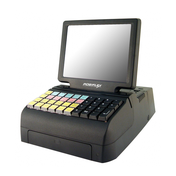
Page 3: Product Pictures
INTRODUCTION PRODUCT PICTURES Front View Inside Front Door Left Side View Rear Top View II Rear View Bottom View Part 3... -
Page 4: Parts Identification
PARTS IDENTIFICATION Display unit Keyboard area (stroke type in the picture) Front Cover Power indicator USB Port Power Switch Front door latch MSR slot Display unit support steel wire 10. UPS battery cover 11. Cable cover 12. Cable cover compression button 13. - Page 5 side) 5. one UPS battery connector 6. one DC 12 V power input connector Support DDR3 SDRAM with maximum memory size 4GB in one SO- m ) m ) m ) m ) DIMM module Built-in UPS function (with battery option) to support system from n ) n ) n ) n ) intermittent power failure.
-
Page 6: Opening Cable Cover
This operation is not open to end user. OPENING CABLE COVER The DT-308 series is constructed for very easy maintenance. Press both plastic compression lock at lower rear corners on both sides of the system unit (circled in right picture) at same time to release the cable cover. - Page 7 DC + 5V support to the COM2/3/4 port that the PD-201 is to be connected to according to Posiflex technical information. Please then open the cable cover and push at the 2...
- Page 8 Have a authorized technician to set a DC + 5V support to the COM port that the PD-309 is to be connected to according Posiflex technical information if it is the RS232 interface model PD-309. The LCD customer display PD-309 or PD-309U can be attached to either rear corner of bottom plate.
-
Page 9: Cash Drawer Connection
The RJ11 connector in connection area of the DT system can be used for controlling most of the common cash drawers available on the market. However, it is most recommended that the Posiflex CR-xxx0 (the fourth digit of the model number being “0” in each cash drawer series) be used for best compliance. -
Page 10: Connecting Cables
OPERATING SYSTEM RECOVERY For DT systems preloaded with operating system on HDD, Posiflex provides recovery CD or DVD delivered with the desktop terminal for the preloaded operating system. The System Integrator shall take care of software restoration after OS recovered. -
Page 11: Application Environment
Battery replacement: In the preloaded WEPOS OS for a DT system, there is a built in utility Posiflex Power Switch Manager that will indicate the UPS battery status of the battery. When an installed UPS battery is found to be... -
Page 12: Power On/Off
disabled or when pop up warning message like this picture appears, please replace the used up UPS battery at power off as soon as possible. Emergency treatment: The battery is constructed maintenance free and leakproof. Its storage space in DT system also provides very good protection as long as the ambient temperature remains below 30°C and the ventilation of the DT system remains free. - Page 13 (the forced power off feature will not work in this mode). When using this feature, please make sure that the software application has the ability to power off the machine. In preloaded Windows, “Posiflex Power Switch Manager” in “Posiflex Tools” in the Program Files helps managing these functions.
-
Page 14: Display Issues
“Power Management Setup” to prepare the system ready to respond to a COM port MODEM Ring or wake up call from an operating caller system connected through LAN to the system. It requires a qualified networking technician to check the LAN chip ID of the system for the caller system to wake the destination system up. - Page 15 Posiflex Touch Terminal Manager A program named “Posiflex Touch Terminal Manager” and a right-click sticky button tool in the program group “Posiflex Tools” is installed in the preloaded Windows system with a PS/2 interface touch panel controller except in WinCE or Linux environment.
- Page 16 Emergency Power Off In case of serious system halt due to any reason, the system could fail to be powered off through normal means. Press and hold the Power ON/OFF Switch for Emergency Power Off. Release the switch after the system powered off. It will take about 10 seconds.
Need help?
Do you have a question about the DT-308 Series and is the answer not in the manual?
Questions and answers