Table of Contents
Advertisement
Quick Links
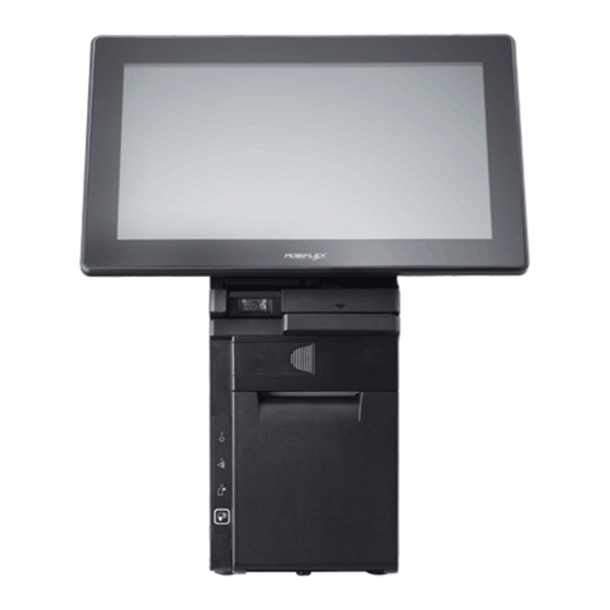
HS-35xxW-G2
Desktop POS
User Manual
Package Contents
15650907010 Ver. A0
http://www.posiflex.com
HS-35xxW-G2 desktop POS (x 1)
24V/100W Power Adaptor (x 1)
Power cord (x 1)
3-inch wide thermal paper roll (x 1)
Paper separator for 2" thermal paper roll (x 1)
Desktop mounting kit pack for HS-3510W-
G2/3512W-G2 (x 1) (including 1 desktop mounting
bracket, 4 fixing screws, and 4 plastic anchors)
Desktop mounting kit pack for HS-3514W-G2 (x 1)
(including 1 bottom plate, 1 desktop mounting
bracket, 4 fixing screws, and 4 plastic anchors)
User manual (x 1)
1
Advertisement
Table of Contents

Related Manuals for POSIFLEX HS-35 W-G2 Series


Summary of Contents for POSIFLEX HS-35 W-G2 Series
- Page 1 4 fixing screws, and 4 plastic anchors) Desktop mounting kit pack for HS-3514W-G2 (x 1) (including 1 bottom plate, 1 desktop mounting bracket, 4 fixing screws, and 4 plastic anchors) User manual (x 1) 15650907010 Ver. A0 http://www.posiflex.com...
- Page 2 SOME IMPORTANT NOTES FCC NOTES This equipment has been tested and found to comply with the limits for a Class A digital device, pursuant to part 15 of the FCC Rules. These limits are designed to provide reasonable protection against harmful interference when the equipment is operated in a commercial environment.
- Page 3 警告使用者 此為甲類資訊技術設備,於居住環境中使用時,可能會造成射頻擾動, 在此種情況下,使用者會被要求採取某些適當的對策。 BATTERY CAUTION NOTES Dispose of used batteries according to the instructions. Replacement of a battery with an incorrect type that can defeat a safeguard (for example, in the case of some lithium battery types) Disposal of a battery into fire or a hot oven, or mechanically crushing or cutting of a battery that can result in an explosion.
-
Page 4: Front View
Views of HS-3510W-G2/3512W-G2/3514W-G2 Front View HS-35xxW-G2 P-CAP Touch & LCD Panel Fingerprint or iButton Sensors (Optional) Posiflex 2D Scanner (Optional) 3-Track Magnetic Paper Jam Rescue Stripe Reader Compartment (Optional) Power LED Indicator Printer Error Printed Paper Exit LED Indicator Printer Paper-Out... - Page 5 Left Side View Right Side View RFID Card Reader (Optional) Power Button Paper Roll Cover Release Lever Bottom View Rubber Pad Rubber Pad Bottom I/O Interface Mounting holes Views of I/O Interface of HS-35xxW-G2 Top I/O Interface USB 3.0 Port VGA Port RJ-50 COM Port DB-25 Parallel Port...
-
Page 6: Connecting Power Adapter
Bottom I/O Interface 24V DC-IN Power Jack RJ-10 Cash Drawer Port Line-Out/Mic-in DB-9 COM Ports USB 2.0 Ports PS/2 Port RJ-45 LAN Port Connecting Power Adapter Please refer to the following instructions on how to connect power adapter to HS-35xxW-G2 and to organize your cables. Lay your desktop POS on a level surface with its touch screen facing down as shown in the figure. - Page 7 Have the cover join to the wedge portions of the bottom I/O interface. Before pushing the cover back into place, neatly thread the cables through the cable exit. Cable Exit Press down the cover to close the bottom I/O interface chamber. CAUTION: On doing insertion or extraction of a cable connector, please always hold the connector head itself instead of...
- Page 8 Before installing 2-inch paper roll in the thermal printer, place paper separator in the paper roll compartment by following the instructions below. If you are using 3” paper roll for the printer, please skip to next step. 2.1. Hold the separator with the sharp- pointed side down.
-
Page 9: Troubleshooting Paper Jams
Unroll the thermal paper and drag the loose end of the paper till it extends towards the paper cutter. Paper cutter Make sure the loose end sticks out of the opening of the paper roll compartment. Then, close the paper roll cover by pushing it back at the center of the top side of the cover with a click sound. - Page 10 In the paper jams rescue compartment, find the adjustment wheel, which mainly allows you to manually adjust the cutting position of the cutter blade. Adjustment wheel Keep rotating the wheel until the cutter blade is completely retracted. Observe the cutter position through the paper exit slot to ensure the cutter blade moves upward to the retracted position.
- Page 11 Position the terminal with its screen facing toward you, and then push down the paper roll cover release lever to open the paper roll cover, Inside the paper roll compartment, remove the two screws indicated by the arrows. While support the terminal with one hand, grab the right-hand side of the terminal and then pull the front cover towards you with force to separate the printer module from the rear case...
- Page 12 Take the new printer module which you wish to replace with, and then connect the cables to the printer control board as indicated in the following figures. Connect the CR cable to CR port on the control board. Insert the cable to the port for printer signal on the control board.
- Page 13 Insert the screw which you removed in step 1 to the screw hole at the bottom, and then fasten it properly, as the figure shows. Mounting the POS onto a Table This section will describe two alternative solutions to help you fix the POS firmly onto a table in preventing your POS system from being rocked, tipped or tilted accidentally.
- Page 14 After inserting another two scerws into the two mouting holes located on the rear of the POS, fasten them to fix the POS termial to the bottom plate. Using desktop-mounting kits Please follow the steps below to install desktop-mounting kits. For HS-3510W-G2/3512W-G2 users, take the mounting bracket out of desktop- mounting kits.
- Page 15 After well attaching two screw holes of the mounting bracket to the plastic anchors, insert two self-tapping screws into the plastic anchors through the mounting bracket and then secure the bracket. Support your POS terminal with its screen facing towards you. Then, align the two screw bolts on the bottom of the POS with the rail slots of the mounting bracket.
- Page 16 Push the POS in the direction shown by the arrow to reomve it from the mouting bracket. After pushing two plastic anchors into the drilled holes, tap the plastic anchors into the drilled holes with a hammer. Refer Step 6 to mount the POS to the bracket. Apply two self-tapping screws through the mounting holes into the two plastic anchors.
- Page 17 Powering ON/OFF the HS-35xxW-G2 Power ON HS-35xxW-G2 To power on the POS, gently press and hold down the power button for at least 1 second till the Power LED indicator turns solid blue, and then release the button. Power Button Power OFF HS-35xxW-G2 For HS-35xxW-G2 which is preloaded with Windows OS, please carefully go through the sequences described below to properly shut down the system:...
-
Page 18: Status Led Indicator
Scanning Barcodes with Posilfex 2D Scanner (Optional) The integrated Posiflex 2D Scanner is another prominent feature of HS- 35xxW-G2. With its hand-free design, it offers a more convenient solution for users to read 1D/2D barcodes and then transmitted scanned data to the terminal for further processing, which greatly increases your working efficiency. -
Page 19: Driver Download
Out of Paper Driver Download If your POS terminal is shipped without OS pre-installed, please download the relevant driver that you need from the Posiflex website (http://www.posiflex.com/en-global/Download/download). Adjusting LCD Monitor for a Better Viewing Angle For an optimal viewing angle, please tilt the LCD monitor up and down in the directions shown by the arrow in the below figure. - Page 20 5, POSTNET, MSI/Plessey, UK/Plessey, Code 128,GS1- Symbology Databar, GS1-Databar Limited, GS1-Databar Expanded, QR Code, PDF417 ※ The product information and specifications are subject to change without prior notice. To get the detailed information on the HS-35xxW-G2, please check this model from Posiflex Global Website.
Need help?
Do you have a question about the HS-35 W-G2 Series and is the answer not in the manual?
Questions and answers