Table of Contents
Advertisement
Quick Links
KS – 7212/X
Fan Free Touch Terminal
User's Manual
Rev.: A0
FCC Notes:
This equipment generates, uses, and can radiate radio frequency energy and, if not
installed and used in accordance with the instructions manual, may cause interference
to radio communications. It has been tested and found to comply with limits for a Class
A digital device pursuant to subpart J of Part 15 of FCC Rules, which are designed to
provide reasonable protection against interference when operated in a commercial
environment. Operation of this equipment in a residential area is likely to cause
interference in which case the user at his own expense will be required to take whatever
measures to correct the interference.
Warranty Limits:
Warranty terminates automatically when any person other than the authorized
technicians opens the machine. The user should consult his/her dealer for the problem
happened. Warranty voids if the user does not follow the instructions in application of
this merchandise. The manufacturer is by no means responsible for any damage or
hazard caused by improper application.
About This Manual:
Posiflex has made every effort for the accuracy of the content in this manual. However,
Posiflex Technology, Inc. will assume no liability for any technical inaccuracies or
editorial or other errors or omissions contained herein, nor for direct, indirect,
incidental, consequential or otherwise damages, including without limitation loss of
data or profits, resulting from the furnishing, performance, or use of this material.
This information is provided "as is" and Posiflex Technology, Inc. expressly disclaims
any warranties, expressed, implied or statutory, including without limitation implied
warranties of merchantability or fitness for particular purpose, good title and against
infringement.
The information in this manual contains only essential hardware concerns for general
user and is subject to change without notice. Posiflex Technology, Inc. reserves the
right to alter product designs, layouts or drivers without notification. The system
integrator shall provide applicative notices and arrangement for special options utilizing
this product. The user may find the most up to date information of the hardware from:
http://www.posiflex.com or http://www.posiflex.com.tw or http://www.posiflexusa.com
All data should be backed-up prior to the installation of any drive unit or storage
peripheral. Posiflex will not be responsible for any loss of data resulting from the use,
disuse or misuse of this or any other Posiflex product.
All rights are strictly reserved. No part of this documentation may be reproduced,
stored in a retrieval system, or transmitted in any form or by any means, electronic,
mechanical, photocopying, or otherwise, without prior express written consent from
Posiflex Technology, Inc. the publisher of this documentation.
© Copyright Posiflex Technology, Inc. 2013
All brand and product names and trademarks are the property of their respective holders.
Part 1
P/N: 16490900020
Advertisement
Table of Contents

Subscribe to Our Youtube Channel
Related Manuals for POSIFLEX KS – 7212/X


Summary of Contents for POSIFLEX KS – 7212/X
- Page 1 About This Manual: Posiflex has made every effort for the accuracy of the content in this manual. However, Posiflex Technology, Inc. will assume no liability for any technical inaccuracies or editorial or other errors or omissions contained herein, nor for direct, indirect, incidental, consequential or otherwise damages, including without limitation loss of data or profits, resulting from the furnishing, performance, or use of this material.
- Page 2 ALERT TO OUR HONORABLE CUSTOMERS: Please always read thoroughly all the instructions and documents delivered with the product before you do anything about it. Don’t take any premature action before you have a full understanding of the consequences. This product contains inside a Lithium battery. Please always follow local environmental protection laws / regulations for disposal of used batteries and always replace only with battery of same type.
-
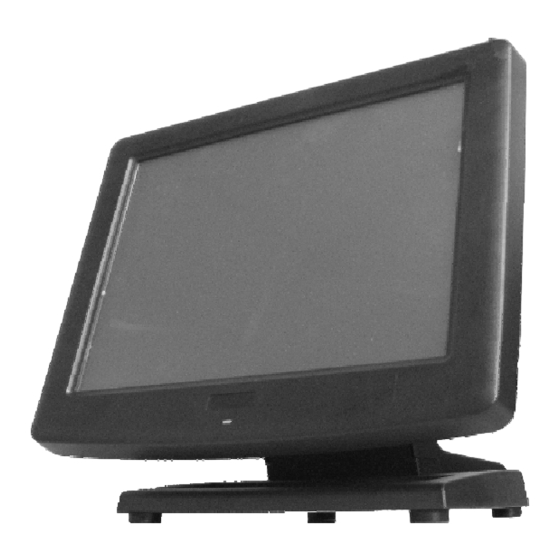
Page 3: Product Pictures
INTRODUCTION PRODUCT PICTURES Front View Rear View Side Views Bottom View Inside Base Part 3... -
Page 4: Parts Identification
PARTS IDENTIFICATION Main unit Touch panel / LCD panel Power indicator Base stand Optional side mount kit HDD cover CF memory card reader Hinge cover Base back cover Cable exit 10. Power switch 11. LCD brightness up button 12. LCD brightness down button 13. -
Page 5: Product Features
COM1 DB9 Com port, connecting to peripherals Connecting to secondary display DC IN Connecting to 12V/50W power supply PRODUCT FEATURES Standard Features: ® CPU: Intel Pineview processor D525 (1M Cache, 1.80 GHz) a ) a ) a ) a ) Chipset: ICH8M b ) b ) b ) b ) Fan free structure for harsh environment... - Page 6 VGA port power supply setting, system CMOS data reset, DRAM upgrades. All these technical maneuver operations require purchase of applicable Technical Manual from Posiflex or consultation from Posiflex authorized dealers and should be handled only by a qualified technician. Part 6...
- Page 7 TILTING LCD PANEL The tilting mechanism for this terminal utilizes hinges and there is no particular skill to turn the LCD panel to most suitable angle for either viewing or convenience in cable connection / disconnection. DISCONNECTING ALL CABLES With the LCD panel turned to most backward position, the main I/O connector area will be easily accessible at bottom side of the main unit.
- Page 8 CABLE ROUTING IN BASE For cable routing in the mini slim base, please refer to the picture at left. There is a cable tie inside the base trunk as arrowed in the picture. Hold all the external cables with the cable tie. Have all cables to pass through the oval hole on the trunk as triangle marked to come out of the front side of trunk.
-
Page 9: Preparing The Main Unit
screws. Slide down the upgrade kit and gently tighten the shoulder screws. Do not overdo the tightening or unrecoverable thread damage will occur. If the customer display used is the USB interface model, the DC supply in COM port is not required, it will be powered through the USB port. - Page 10 The following table depicts the usage of all the ports under service window. However, it is highly recommended only the trained or certified technician should configure the DIP switch, for incorrect configurations might cause unexpected results or even damage the terminal. Label Description Connects to the parallel device via a conversion cable.
-
Page 11: Connecting Cables
The RJ11 connector in I/O area of the terminal can be used for controlling most of the common cash drawers available on the market. However, it is most recommended to use Posiflex CR-2200 or CR-2210 or CR-3100 or CR-4000 or CR-4100 or CR-6300 for best compliance to operate the opening mechanism and to monitor the drawer open status. -
Page 12: Operating System Recovery
OPERATING SYSTEM RECOVERY For the terminal preloaded with operating system in HDD, Posiflex provides recovery DVD delivered with the touch terminal for the preloaded operating system. The System Integrator shall take care of software restoration after OS recovered. -
Page 13: Power On/Off Control
Operating Environment The equipment must not be operated or stored in extremes of both temperature and humidity/moisture. (Operating range 0°C to 40°C and up to 80% humidity – non condensing, max. wet bulb 26°C) Power Supply The operating voltage range of the power adaptor should cover the local power supply for proper operation. -
Page 14: Brightness Control
To utilize Alarm Clock Wake Up function, the user should enter the BIOS setup by pressing “Del” key at system boot up, choose in “Power Management Setup” and make the “Resume by Alarm” for Alarm Clock Wake Up. Save the configuration and exit the BIOS setup program. - Page 15 KS main unit to supply the required power through the VGA connector according to Posiflex technical information. Do not connect other monitor to this port before the power in this port is disabled.
- Page 16 Manager is already installed on your system. Nevertheless, you can also download the Manager from our website: Visit us at http://www.posiflex.com, and click Support on the main menu bar. On Support page, click Download on the left to access Download page.
Need help?
Do you have a question about the KS – 7212/X and is the answer not in the manual?
Questions and answers