Table of Contents
Advertisement
KS- 6315 / 6317
Fanless Touch Terminal
w/ Slim or Universal Base
User's Manual
Original
FCC Notes:
This equipment generates, uses, and can radiate radio frequency energy and, if not
installed and used in accordance with the instructions manual, may cause interference
to radio communications. It has been tested and found to comply with limits for a Class
A digital device pursuant to subpart J of Part 15 of FCC Rules, which are designed to
provide reasonable protection against interference when operated in a commercial
environment. Operation of this equipment in a residential area is likely to cause
interference in which case the user at his own expense will be required to take whatever
measures to correct the interference.
Warranty Limits:
Warranty terminates automatically when any person other than the authorized
technicians opens the machine. The user should consult his/her dealer for the problem
happened. Warranty voids if the user does not follow the instructions in application of
this merchandise. The manufacturer is by no means responsible for any damage or
hazard caused by improper application.
About This Manual:
Posiflex has made every effort for the accuracy of the content in this manual. However,
Posiflex will assume no liability for any technical inaccuracies or editorial or other
errors or omissions contained herein, nor for direct, indirect, incidental, consequential
or otherwise damages, including without limitation loss of data or profits, resulting
from the furnishing, performance, or use of this material.
This information is provided "as is" and Posiflex Inc. expressly disclaims any
warranties, expressed, implied or statutory, including without limitation implied
warranties of merchantability or fitness for particular purpose, good title and against
infringement.
The information in this manual contains only essential hardware concerns for general
user and is subject to change without notice. Posiflex reserves the right to alter product
designs, layouts or drivers without notification. The system integrator shall provide
applicative notices and arrangement for special options utilizing this product. The user
may find the most up to date information of the hardware from web sites:
http://www.posiflex.com or http://www.posiflex.com.tw or http://www.posiflexusa.com
All data should be backed-up prior to the installation of any drive unit or storage
peripheral. Posiflex will not be responsible for any loss of data resulting from the use,
disuse or misuse of this or any other Posiflex product.
All rights are strictly reserved. No part of this documentation may be reproduced,
stored in a retrieval system, or transmitted in any form or by any means, electronic,
mechanical, photocopying, or otherwise, without prior express written consent from
Posiflex Inc. the publisher of this documentation.
© Copyright Posiflex Inc. 2006
All brand and product names and trademarks are the property of their respective holders.
Part 1
P/N: 16520900010
Advertisement
Table of Contents

Related Manuals for POSIFLEX KS-6315


Summary of Contents for POSIFLEX KS-6315
- Page 1 KS- 6315 / 6317 Fanless Touch Terminal w/ Slim or Universal Base User’s Manual Original FCC Notes: This equipment generates, uses, and can radiate radio frequency energy and, if not installed and used in accordance with the instructions manual, may cause interference to radio communications.
- Page 2 ALERT TO OUR HONORABLE CUSTOMERS: l Please always read thoroughly all the instructions and documents delivered with the product before you do anything about it. Don’t take any premature action before you have a full understanding of the consequences. l This product contains inside a Lithium battery and maybe also a sealed type Lead acid battery if the UPS battery option is ordered.
-
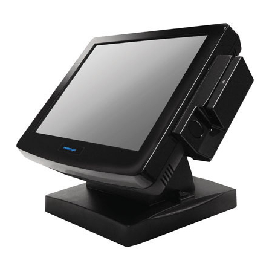
Page 3: Product Pictures
INTRODUCTION PRODUCT PICTURES Front Views for KS-6315/6317; AMD LX-700 for KS-6115 1. one optional Compact Flash memory card connector 2. one IDE connector and HDD power connector for HDD in base ² SD500 covering options of USB interface WiFi and Audio ports ²... -
Page 4: Parts Identification
Rear Views KS-6317 KS-6315U Bottom Views Slim Base Universal Base PARTS IDENTIFICATION Main unit Touch panel / LCD panel Optional side mount kit e.g. SD-400 Power indicator Universal base stand Optional CDROM drive Slim base stand Cable cover Removal hollow in cable cover 10. -
Page 5: Product Features
Support WinCE, Win 2000, Win XP Pro, WEPOS and Linux environment High quality 15” TFT active matrix LCD panel for KS-6315. High quality 17” TFT active matrix LCD panel for KS-6317 Brightness control by either software or hardware Vertical type LCD panel with easy tilt angle adjustment from 17.5°... - Page 6 Internal slim type CD ROM or COMBO drive in universal base UPS battery in base Preload OS Model Numbers: KS-6315: 15” LCD & touch, slim base KS-6315U: 15” LCD & touch, universal base KS-6317: 17” LCD & touch, slim base KS-6317U: 17” LCD & touch, universal base...
-
Page 7: Opening Cable Cover
INSTALLATION GUIDES CAUTION: Before any installation or cable connection to the set, please always make certain that the system is turned off and the external power source to the set is removed to prevent electric hazard! Never touch any metal pin in the connectors or circuits to avoid high voltage hazard or electrostatic discharge damage unless the operator is well grounded. -
Page 8: Separating Main Unit
SEPARATING MAIN UNIT In order to settle the touch terminal properly in a point of sale system, all the cable connections have to be routed through its base, either slim or universal. Therefore, please observe the procedures from A to C below to separate the main unit from both slim and universal base stand assembly after all cables in cable cover disconnected. -
Page 9: Cable Passage
1. Cable Exit For External Connections 2. Base Box Screw 3. Cable tie 4. CD-ROM Bracket For Universal Base 5. Cable Passage To Main Unit For Desktop Mount Application 6. Cable Passage To Main Unit For Wall Mount Application 7. HDD Bracket Fixing Screw Inside universal base 8. -
Page 10: Wall Mounting
left picture then apply the fixing screw. Please pay particular attention to the environment requirements for UPS battery in next chapter “USING THE TOUCH POS”. WALL MOUNTING Select a flat surface on wall of adequate strength and with proper ventilation and space condition. Please use the right material to hold this terminal according to the wall material (Drywall, concrete, solid wood, etc). -
Page 11: Base Mount Upgrade Kit
The area required for wall mount application is determined by the main unit dimensions and is 381 mm in width and 305 mm in height for KS-6315 and is 406 mm in width and 343 mm in height for KS-6317. -
Page 12: Preparing The Main Unit
Now, turn the adjustable stand assembly back to normal orientation and arrange all cables to come out of the area for mounting main unit from the bottom edge for ease of later operation. PREPARING THE MAIN UNIT On the back of the main unit, there is a service window among the 4 matching pegs. -
Page 13: Connecting Cables
For desk top/counter application, the body of KS-6315 occupies a space of 381 mm wide, 265 mm deep and 267 to 357 mm high per main unit tilt angle. -
Page 14: Operating System Installation
HDD, usual utilities such as FDISK.EXE or FORMAT.COM shall never be used on CF Card otherwise the boot sector of operating system itself may be damaged and causing the CF Card no longer bootable. For KS systems preloaded with Windows XP Pro or WEPOS on HDD, Posiflex provides recovery CD delivered with the touch terminal for the preloaded operating system. -
Page 15: Application Environment
USING THE TOUCH TERMINAL APPLICATION ENVIRONMENT It is very important that you check the following operational guidelines: Ventilation This terminal must NOT be operated in an environment with restricted ventilation. There must be at least 25 mm air clearance around any top or side ventilation holes with a free flow of air around the unit at ALL times for the installation. -
Page 16: Power On/Off
Emergency treatment: The battery is constructed maintenance free and leakproof. It is well protected in KS system as long as the ambient temperature remains below 30 C and the ventilation of the KS system remains free. However, should any accident happen and the sulfuric acid from the battery spills on skin or clothing, wash immediately with water. - Page 17 other conditions is summarized in following table: System External Indicator Status UPS Battery Powering Up Status Power Not present Not possible Present Not allowed Green No influence Allowed Blue No influence Not required Blue/flash Activated Not required Running at Green/rapid flash Not required low capacity Hardware Power Switch...
-
Page 18: Display Issues
Main LCD Display For best viewing result please set your display resolution at 1024 x 768 with high color for KS-6315 and set it at 1280 x 1024 with high color for KS-6317. In configuration of system memory, max. 32 MB can be shared as the video memory. -
Page 19: Serial Ports - Com1
Mouse Emulation The touch panel in KS system uses USB interface as standard. Only the optional InfraRed type touch panel of KS-6315 uses RS232 interface. When the touch driver is properly installed, this touch panel works exactly like a standard mouse for both interfaces. However, if the system is running under safe mode, most drivers are disabled in this mode and the touch panel calibration is therefore not guaranteed. - Page 20 the right button of the mouse at that point. Posiflex USB Touch Manager A program named “Posiflex USB Touch Manager” and a right-click sticky button tool in the program group “Posiflex USB Touch Tools” is installed in the preloaded Windows system with a USB interface touch panel controller.
Need help?
Do you have a question about the KS-6315 and is the answer not in the manual?
Questions and answers