Advertisement
Quick Links
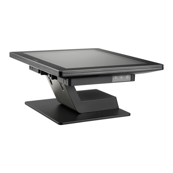
RT-5015/5016/5115/5116
Fanless Touch POS Terminal
User Manual
16940900010 Ver. A0
http://www.posiflex.com
Package Contents
RT-5015 15" fanless touch terminal or
RT-5016 15.6" fanless touch terminal or
RT-5115 15" fanless touch terminal or
RT-5116 15.6" fanless touch terminal (x 1)
Power adapter (x 1)
Power cord (x 1)
User manual (x 1)
1
Advertisement


Need help?
Do you have a question about the RT-5015 and is the answer not in the manual?
Questions and answers