
Related Manuals for Kargo Master 406GMF-P


Summary of Contents for Kargo Master 406GMF-P
- Page 1 Instruction Guide 406GMF-P Kargo Master Rancho Cordova, CA 95742 800-343-7486 CustomerService@KargoMaster.com 20210319R1 DATE: ________________...
-
Page 2: Table Of Contents
Step 5 – Install Partition ............................ 8 Before You Begin Read all instructions prior to assembling or installing any Kargo Master product. Always locate your installation locations prior to performing any work. ENSURE SAFETY WHILE INSTALLING INTO VEHICLE. -
Page 3: Parts
Instructions – 406GMF-P Parts For Technical Support Call: 800-343-7486 Monday-Friday 7AM - 4 PM (PST) Page 2... -
Page 4: Hardware (18-406Gmf-P)
Instructions – 406GMF-P Hardware (18-406GMF-P) Hardware (18-40600) For Technical Support Call: 800-343-7486 Monday-Friday 7AM - 4 PM (PST) Page 3... -
Page 5: Step 1 - Install Floor Mounts
Instructions – 406GMF-P DO NOT EXCEED MANUFACTURERS WEIGHT CAPACITY FOR ROOF Step 1 – Install Floor Mounts Behind both seats, locate the D-Rings in the floor. Remove both D-Rings. Align the floor mounts with the previously removed D-Rings. Orient the vertical flanges on floor mounts towards rear of the van. -
Page 6: Step 2 - Install Upper Corner Mounts
Instructions – 406GMF-P Step 2 – Install Upper Corner Mounts Along the roof of the van, locate the mount locations behind both seats. These are above the slider door. Evaluate the mounting locations and determine if a threaded emboss is present. -
Page 7: Step 3 - Attach Upper Mount To Corner Mounts
Instructions – 406GMF-P If there is no threaded emboss on the forward most hole location, install corner mount using a M6 x 22mm hex head bolt, two 1/4” flat washers and 1/4” lock nut in the orientation shown. Snug tighten, but allow movement. -
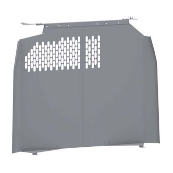
Page 8: Step 4 - Join Partition Panels
Instructions – 406GMF-P Using two 1/4” x 5/8” flanged hex head bolts and two 1/4” flanged lock nuts, LOOSELY bolt upper mount to opposing corner mount. DO NOT tighten! Step 4 – Join Partition Panels Using four 1/4” x 5/8” flanged hex head bolts and 1/4” flanged lock nuts, attach driver-side partition panel to passenger-side partition panel. -
Page 9: Step 5 - Install Partition
Instructions – 406GMF-P Attach rubber edge trimming to outer edges of partition panels. Repeat for opposite side. Step 5 – Install Partition Position partition in vehicle. Flanges on partition are towards rear of vehicle. Using six 1/4” x 5/8” flanged hex head bolts and 1/4” flanged lock nuts, LOOSELY bolt partition to upper mount. - Page 10 Instructions – 406GMF-P Using four 1/4” x 1/2” hex head bolts, 1/4” lock washers, 1/4” flat washers, bolt partition to nuts pressed in floor mounts. Snug tighten but allow for movement. Shown from below for clarity. Re-install previously removed D-rings.
Need help?
Do you have a question about the 406GMF-P and is the answer not in the manual?
Questions and answers