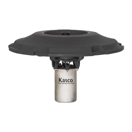
Kasco J Series Operation & Maintenance Manual
Hide thumbs
Also See for J Series:
- Operation & maintenance manual (17 pages) ,
- Owner's manual (14 pages) ,
- Operation & maintenance manual (16 pages)
Table of Contents
Advertisement
Quick Links
MOVING WATER FORWARD, SINCE 1968
J SERIES
FOUNTAIN
8400, 2.3, 3.1, 3.3
Operation &
Maintenance
Manual
3020379
ANSI/UL 778: 2016
Ed.6+R:22Feb2017
CSA C22.2 #108: 2014 Ed.5
Document number 884168
Document version 2021.2.0
800 Deere Rd. Prescott, WI 54021 | 715.262.4488 | sales@kascomarine.com | kascomarine.com
2HP-5HP J SERIES FOUNTAIN MANUAL
1
Advertisement
Table of Contents

Summary of Contents for Kasco J Series
- Page 1 8400, 2.3, 3.1, 3.3 Operation & Maintenance Manual 3020379 ANSI/UL 778: 2016 Ed.6+R:22Feb2017 CSA C22.2 #108: 2014 Ed.5 Document number 884168 Document version 2021.2.0 800 Deere Rd. Prescott, WI 54021 | 715.262.4488 | sales@kascomarine.com | kascomarine.com 2HP-5HP J SERIES FOUNTAIN MANUAL...
-
Page 2: Table Of Contents
Parts Included .........................4 Nozzles Included ........................5 Premium Nozzles (Not Included) ..................6 Unit Installation Instructions ....................11 Maintenance Recommendations ..................13 Troubleshooting Tips ......................14 Warranty ..........................15 Non-Warranty Repairs ......................16 Repair Contact Form ......................17 QUESTIONS? 715.262.4488 kascomarine.com | sales@kascomarine.com 2HP-5HP J SERIES FOUNTAIN MANUAL... -
Page 3: Safety First
• Kasco Aerating Fountains are intended for use with a Listed control panel having a GFCI protected re- ceptacle, or field wiring terminals and disconnect switch, or a timer with a disconnect for use with a GFCI receptacle. -
Page 4: Unit Specifications
Model Voltage Control Panel Connection Unit Connection Amps Amps Single-Phase Units 8400JF 208-240 Hardwire C-85 Hardwire C-85 3.1JF 208-240 13.4 Hardwire C-95 Hardwire C-95 3-Phase Units 2.3JF 3.3JF 10.3 See control panel instructions 2.3HJF 3.3HJF 2HP-5HP J SERIES FOUNTAIN MANUAL... -
Page 5: Parts Included
Unit Size Voltage/Phase G (Part #) D (Part #) 208-240 / 1p 8400JF 2 HP 208 / 3p 2.3JF 284102 460 / 3p 2.3HJF 208-240 / 1p 3.1JF 3 HP 208 / 3p 3.3JF 284103 460 / 3p 3.3HJF 2HP-5HP J SERIES FOUNTAIN MANUAL... -
Page 6: Nozzles Included
Balsam and Linden nozzles. dimensions 841232 *Pattern sizes listed are approximate. Variations in voltage caused by regional electrical differences or voltage drop due to long power cords may result in reduced pattern sizes. Birch Spruce Balsam Linden Redwood 2HP-5HP J SERIES FOUNTAIN MANUAL... -
Page 7: Premium Nozzles (Not Included)
Premium nozzles are not included as standard but may be added and installed at any time. These nozzles offer unique patterns that truly showcase your pond or lake. Contact Kasco Marine at sales@kascomarine. com or your local distributor for order information. - Page 8 1. Place the float (D) over the unit assembly (G). Ensure the three channels on the inside of the float line up with the threaded holes in the baseplate, and the Kasco logo on the top side of the float lines up with the power cord on the unit assembly.
- Page 9 4. Lift the unit and slide the bottom float screen (H) over the can and up to the bottom of the float, allowing the unit power cord to exit between them in the dedicated channel. Dedicated power cord channel 2HP-5HP J SERIES FOUNTAIN MANUAL...
- Page 10 If your Kasco cord comes with a strain relief kit at- tached, attach the available link to the float-side knot in the mooring rope, as pictured here.
- Page 11 First ensure that the large Outlet nozzle is properly installed according to the above instructions. Insert the Balsam or Linden components and thread into the insert at the top of the pump chamber, tightening every- thing by hand until snug. Do not over-tighten. Balsam Linden OUTLET (6) nozzle installed 2HP-5HP J SERIES FOUNTAIN MANUAL...
-
Page 12: Unit Installation Instructions
Low water level High water level After unit is installed in the water, connect the power cord to a properly installed Kasco control panel (C-85, C-95, etc.) with built-in ground fault protection according to the instructions and electrical schematics in- cluded with the panel. - Page 13 Keep clear of the propeller while verifying rotation. Air will be blowing out (up) of the pump chamber when rotating in the correct direction. If a Kasco 3-phase panel is supplied, follow the instructions included with the panel in addition to the steps below.
-
Page 14: Maintenance Recommendations
(at least every two to three months). Seal replacement and all other repair services should be performed by Kasco Marine or a Kasco-trained Au- thorized Repair Center. Any alterations or changes made to Kasco units by an unauthorized source will void the warranty. -
Page 15: Troubleshooting Tips
Try to find out the answers to these questions before you contact Kasco to narrow down the problem: How long does it take to trip the breaker? •... -
Page 16: Warranty
(excluding ropes, power cord, and propeller). The Kasco Marine, Inc. obligation under this warranty is limited to replacing or repairing free of charge any defective part within the warranty period from the date of shipment. Customer shall pay shipping charges for returning the unit to Kasco or an Autho- rized Repair Center. -
Page 17: Non-Warranty Repairs
Please ship according to the instructions on the previous provided. Kasco Marine does estimates on repairs at the request of the customer. The request for estimate should be included in the letter that accompanies the returned unit and must include a daytime phone number and/ or e-mail address. -
Page 18: Repair Contact Form
Back to Contents REPAIR CONTACT FORM • Kasco requires that all equipment sent for repair MUST be accompanied by this form and marked to Repairs attention. Kasco Marine • Unit should be cleaned before shipping. 800 Deere Road • Kasco is NOT responsible for shipping damage accrued in Prescott, WI 54021 return shipment.


Need help?
Do you have a question about the J Series and is the answer not in the manual?
Questions and answers