
Related Manuals for AMX Modero X MXT-700


Summary of Contents for AMX Modero X MXT-700
- Page 1 Operation/Reference Guide MXT/D-700 7" Modero X Series® Tabletop Touch Panel 7" Modero X Series® Wall/Flush Mount Touch Panel Touch Panels L a s t U p d a t e d : 1 2 / 1 2 / 2 0 1 2...
- Page 2 AMX is not responsible for products returned without a valid RMA number. AMX is not liable for any damages caused by its products or for the failure of its products to perform. This includes any lost profits, lost savings, incidental damages, or consequential damages.
- Page 3 LICENSE GRANT. AMX grants to Licensee the non-exclusive right to use the AMX Software in the manner described in this License. The AMX Software is licensed, not sold. This license does not grant Licensee the right to create derivative works of the AMX Software.
-
Page 5: Table Of Contents
Table of Contents Table of Contents Modero X Series® Touch Panels ................1 Overview ........................1 Features........................1 Modero X Series Dealer Benefits................1 Modero X Series Customer Benefits ................. 1 MXT-700 ........................2 Connector Locations ....................... 4 Memory........................... 4 Basic Operation....................... 4 Powering on the MXT-700 .................... - Page 6 Table of Contents Uninstalling the MXD-700..................21 Configuration and Programming ..............23 Modero X Series Programming Guide ..............23 Upgrading Firmware ..................25 Overview ........................ 25 Upgrading Firmware via USB Flash Drive ............... 25 Load the Firmware on a USB Flash Drive ..............25 Transfer the Firmware File From the Flash Drive to the Touch Panel......
-
Page 7: Modero X Series Touch Panels
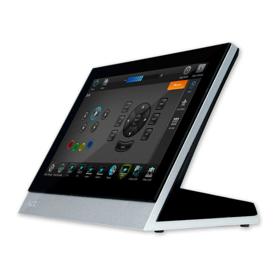
Modero X Series® Touch Panels ® Modero X Series Touch Panels Overview See more and do more with the most elegant interface designed specifically for dedicated room control. The ® Modero X Series Touch Panels provide several industry firsts, including a beautiful, panoramic capacitive multi-touch screen that provides users access to multiple applications with minimal navigation. - Page 8 Modero X Series® Touch Panels MXT-700 The MXT-700 7" Modero X® Series Tabletop Touch Panel (FG5968-04) (FIG. 1) is ideal for boardrooms, conference rooms, or auditoriums where a panoramic control surface is needed to provide access to multiple functions simultaneously while remaining elegantly unobtrusive. In residences, it is perfect for kitchens, home theaters, or home offices where the panoramic control surface can be used to manage systems throughout the house.
- Page 9 Modero X Series® Touch Panels MXT-700 Specifications Power Requirements: PoE (Power over Ethernet), 802.3af, class 3 Power Consumption: • Full-On: 8W maximum • Standby: 3.2 W • Shutdown: 1 W Front Panel Components: NFC Transceiver: Antenna and transceiver for Near Field Communications device detection and interaction.
-
Page 10: Mxt-700
Streaming/File Formats: WAV, MP3 Intercom: Full Duplex VoIP, SIP v2.0 (supported with AMX-CSG) Operating Environment: • Operating Temperature: 32° F to 104° F (0° C to 40° C) • Storage Temperature: 4° F to 140° F (-20° C to 60° C) •... -
Page 11: Powering On The Mxt-700
Modero X Series® Touch Panels Powering on the MXT-700 The MXT-700 may be powered on by touching and holding the Sleep button on the top of the device. Microphone The MXT-700 contains a built-in microphone above the touch screen for video and audio conferencing capabilities. - Page 12 Modero X Series® Touch Panels Sleep Button NFC Sensor FIG. 5 MXD-700 (Portrait Wall Mount) MXD-700 Specifications Power Requirements: PoE (Power over Ethernet), 802.3af, class 3 Power Consumption: • Full-On: 8W maximum • Standby: 3.2 W • Shutdown: 1 W Front Panel Components: NFC Transceiver: Antenna and transceiver for Near Field Communications device detection and...
- Page 13 Audio: Streaming/File Formats: WAV, MP3 Intercom: Full Duplex VoIP, SIP v2.0 (supported with AMX-CSG) Operating • Operating Temperature: 32° F to 104° F (0° C to 40° C) Environment: • Storage Temperature: 4° F to 140° F (-20° C to 60° C) •...
-
Page 14: Memory
Modero X Series® Touch Panels MXD-700 Specifications (Cont.) Other AMX Equipment: • PS-POE-AT, High Power PoE Injector (FG423-81) • PS-POE-AF-TC, POE Injector, 802.3af Compliant (FG423-83) • MXA-BT Bluetooth USB Adaptor (FG5968-19) • CB-MXP7, Rough-In Box and Cover Plate for Modero X Series Touch Panel, 7"... -
Page 15: Mxd/T-700 Features
Modero X Series® Touch Panels MXD/T-700 Features Picture View By connecting a USB drive via one of the device’s USB ports (FIG. 3), Picture View allows the MXT-700 to access JPEG images on that drive and display them on the touchscreen (FIG. 7). Individual images may be accessed at any time, or the entire collection may be displayed for predetermined times. -
Page 16: Preview Mode And Normal Mode
Modero X Series® Touch Panels Pause/ Stop Resume Counter Random/ Previous image Timer Next image saved saved FIG. 8 Picture View configuration popup menu On the leftmost amber button, select between Rand (images display at random) and A-Z (images display in alphabetical order based on the name of the file). -
Page 17: Picture View Send Command
To facilitate NFC antenna access, you may want to add an icon to the panel’s page(s), pointing to the location of the antenna on the panel. For further information, please refer to the video available at the AMX Configure channel on YouTube: http://www.youtube.com/user/AMXconfigure... -
Page 18: Cleaning The Touch Overlay And Case
Modero X Series® Touch Panels Cleaning the Touch Overlay and Case Both the MXT-700 and the MXD-700 come with the MXA-CLK Modero X Series Cleaning Kit (FG5968-16), which may be used to clean fingerprints and dirt from the device. This kit comes with cleaning cloths and a bottle of cleaning fluid specifically for use with the device. -
Page 19: Installation
Connectors on the rear of the MXT-700 Power via Power Over Ethernet Power for the MXT-700 is supplied via Power Over Ethernet (PoE), utilizing an AMX-certified, capacitive touch-compliant PoE injector or other approved AMX PoE power source. The incoming Ethernet cable should be connected to the RJ45 port on the cable attached to the device (FIG. - Page 20 Installation Ethernet Cable MXT-700 Clamp Connector FIG. 11 Bottom of the MXT-700 To disconnect and reconnect the MXT-700’s Ethernet cable to allow use of a hole smaller than 1.00” in diameter: On a soft surface, turn the MXT-700 face-down to access the bottom of the device. Remove the clamp holding the Ethernet cable (FIG.
-
Page 21: A Note About Wall And Rack Installation
FIG. 12 shows an AMX device installed in a wall with a filled volume (such as with insulation or concrete), as well as with a closed volume (such as between studs in an otherwise finished wall). The diagram shows how heat generated by the device or other devices may have no way to escape, and may build up to levels that may affect device operation. -
Page 22: Installation Recommendations
MXD-700 Back Box Power Via Power Over Ethernet Power for the MXD-700 is supplied via Power Over Ethernet (PoE), utilizing an AMX-certified, capacitive touch-compliant PoE injector or other approved AMX PoE power source. The incoming Ethernet cable should be connected to the RJ45 port on the MXD-700 (FIG. 15 and FIG. 16). -
Page 23: Installing The Mxd-700 Into A Wall
Installation RJ45 Cable Clip RJ45 Port FIG. 16 Rear of the MXD-700 (with RJ45 connection extended) Installing the MXD-700 into a wall The MXD-700 comes with a clear plastic backbox (designed to attach the panel to most standard wall materials. This backbox has two locking tabs (one on top and one on bottom) to help lock the backbox to the wall. - Page 24 Installation The maximum recommended torque to screw in the locking tabs on the plastic back box is 5 IN-LB [56 N-CM]. Applying excessive torque while tightening the tab screws, such as with powered screwdrivers, can strip out the locking tabs or damage the plastic back box.
- Page 25 Installation Thread the incoming Ethernet from their terminal locations through the surface opening (FIG. 19). Leave enough slack in the wiring to accommodate any re-positioning of the panel. Mounting Surface Locking Back Box #4 Screws Knockouts FIG. 19 MXD-700 Back Box Installation (Landscape) Remove the back box knockouts (FIG.
- Page 26 Installation Test the incoming wiring by attaching the panel connections to their terminal locations and applying power. Verify that the panel is receiving power and functioning properly to prevent repetition of the installation. Do not disconnect the connectors from the touch panel. The unit must be installed with the attached connectors before being inserted into the mounting surface.
-
Page 27: Uninstalling The Mxd-700
Installation Uninstalling the MXD-700 The MXD-700 is held in place to the back box via latch hooks and clips on the back box (FIG. 21), securing it to the mounting surface. In certain circumstances, such as firmware updates or other maintenance that requires accessing the device’s USB port, the device may need to be removed from the back box. - Page 28 Installation MXD/T-700 7" Modero X Series® Touch Panels...
-
Page 29: Configuration And Programming
Configuration and Programming Programming the MXT-700 and MXD-700 require the use of the latest versions of NetLinx Studio and TPDesign 4, both available at www.amx.com. Modero X Series Programming Guide Information on Settings pages, panel configuration, and programming is included in the Modero X Series Programming Guide, available at www.amx.com. - Page 30 Configuration and Programming MXD/T-700 7" Modero X Series® Touch Panels...
-
Page 31: Upgrading Firmware
Upgrading Firmware Overview The latest firmware (*.kit) file for each panel is available to download from www.amx.com. To download firmware files, go to the catalog page for your panel type, and click the link under "Firmware Files" on the right side of the catalog page (FIG. 23): FIG. -
Page 32: Transfer The Firmware File From The Flash Drive To The Touch Panel
Upgrading Firmware Make sure this is the only .kit file in this directory - if not, the latest version will be used. Eject or unmount the flash drive from the PC. Transfer the Firmware File From the Flash Drive to the Touch Panel Connect the USB Flash Drive to one of the USB Type A ports on the panel. -
Page 33: Upgrading From Previous Firmware
Upgrading Firmware Upgrading from Previous Firmware The MXT-700 and MXD-700 allow the option to revert the device to the previous firmware run before an upgrade. To upgrade the device from previously loaded firmware: From the Settings page, select the Configuration page. From the Configuration page, select Admin. -
Page 34: Upgrading Firmware Via Netlinx Studio
Upgrading Firmware Upgrading Firmware Via NetLinx Studio The MXT-700 and MXD-700 use an Ethernet connection for programming, firmware updates, and touch panel file transfer via NetLinx Studio. If you have access to the panel’s network, you may transfer files directly to the panel through NetLinx Studio Firmware upgrades cannot be made through an Ethernet-connected PC to the touch panel, unless that PC is connected to the panel’s network. - Page 35 Upgrading Firmware Click the Edit Settings button on the Communications Settings dialog to open the Virtual NetLinx Master Settings dialog (FIG. 29). FIG. 29 Virtual NetLinx Master Settings Within this dialog, enter the Master System number. The default is 1. In the Available Connections section, click on the IP address for the touch panel to select it.
-
Page 36: Viewing Devices On The Virtual System
The panel-specific firmware is shown on the right of the listed panel. Download the latest firmware file from www.amx.com and then save the Kit file to your computer. Note that each Kit file is intended for download to its corresponding panel. - Page 37 System list with devices on your particular system. Confirm that the panel has been properly updated to the correct firmware version. Verify you have downloaded the latest firmware file from www.amx.com and then save the Kit file to your computer.
- Page 38 Upgrading Firmware MXD/T-700 7" Modero X Series® Touch Panels...
-
Page 39: Appendix: Troubleshooting
Appendix: Troubleshooting Appendix: Troubleshooting Overview This section describes the solutions to possible hardware/firmware issues that could arise during the common operation of a Modero X touch panel. Panel Doesn’t Respond To Touches Symptom: The device either does not respond to touches on the touch screen or does not register the touch as being in the correct area of the screen. - Page 40 Appendix: Troubleshooting MXD/T-700 7" Modero X Series® Touch Panels...
- Page 41 Appendix - Troubleshooting MXD/T-700 7" Modero X Series® Touch Panels...
- Page 42 It’s Your World - Take Control™ 3000 RESEARCH DRIVE, RICHARDSON, TX 75082 USA • 800.222.0193 • 469.624.8000 • 469-624-7153 fax • 800.932.6993 technical support • www.amx.com...
Need help?
Do you have a question about the Modero X MXT-700 and is the answer not in the manual?
Questions and answers