AMX Modero X Series Quick Start Manual
4.3" wall/flush mount touch panel
Hide thumbs
Also See for Modero X Series:
- Installation manual (2 pages) ,
- Quick start manual (2 pages) ,
- Quick start manuals (2 pages)
Advertisement
Quick Links
Overview
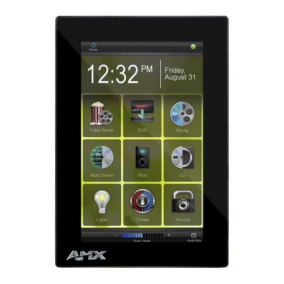
The MXD-430 4.3" Modero X Series Wall/Flush Mount Touch Panel (FG5968-15) features
edge-to-edge capacitive touch glass with multi-touch capabilities as well as advanced
technology empowering users to operate AV equipment seamlessly, while providing the
ultimate in audio and video quality. The distinctive appearance will complement even the
most sophisticated meeting facilities and homes.
Left LED
Right LED
Sleep
Button
NFC
Sensor
front
FIG. 1
MXD-430
Product Specifications
MXD-430 Specifications
Dimensions (HWD)
4 7/8" x 3 1/4" x 2 3/8" (120 mm x 82 mm x 61 mm)
Weight
0.75 lbs (.34 Kg
Power Consumption
• Full-On: 6.5 W
• Standby: 4.2 W
• Shutdown: 1.9 W
• Start-Up Inrush Current: Not applicable due to PoE
standard
External Power
Optimal performance requires use of one of the following
Supply Required
AMX PoE power supplies (not included):
• PS-POE-AF-TC, PoE Injector, 802.3AF Compliant
(FG423-83)
• NXA-ENET8-2POE, Gigabit PoE Ethernet Switch
(FG2178-63)
Certifications
• UL 60950-1
• FCC Part 15 Class B
• C-Tick CISPR 22 Class B
• CE EN 55022, EN 55024 and EN 60950-1
• IEC 60950-1
• IC
• IEC/EN-60950
• RoHS / WEEE compliant
Environmental
• Temperature (Operating): 32° F to 104° F (0° C to 40° C)
• Temperature (Storage): 4° F to 140° F (-20° C to 60° C)
• Humidity (Operating): 20% to 85% RH
• Humidity (Storage): 5% to 85% RH
• Power ("Heat") Dissipation:
On: 22.2 BTU/hr
Standby: 14.3 BTU/hr
Included
• MXA-USB-C, USB Port Cover Kit (FG5968-18)
Accessories
• MXA-CLK, Modero X/S Series Cleaning Kit (FG5968-16)
• MXD-430 Installation Template
Connector Locations
USB peripherals (mouse, keyboard, etc.) may be connected to either of the two USB
ports on the rear of the device (see FIG. 1). The connectors are accessible via the
Access Slot shown in FIG. 2. and FIG. 3.
Updates to the device's firmware can also made via the USB ports.
MXD-430
USB
Port
rear
4.3" Modero X Series
Power via PoE
Power for the MXD-430 is supplied via Power Over Ethernet (PoE), utilizing an
AMX-certified, capacitive touch-compliant PoE injector such as the PS-POE-AF-TC High
Power PoE Injector (FG423-83) or other approved AMX PoE power source.
The incoming Ethernet cable should be connected to the RJ45 port on the MXD-430 (FIG. 2).
Front
USB Port
FIG. 2
Bottom View - showing RJ45 and USB ports
RJ45
Port
Installing the MXD-430 Into a Wall
The MXD-430 comes with a clear plastic Backbox (designed to attach the panel to most
standard wall materials. This Backbox has two locking tabs (one on each side) to help lock
the Backbox to the wall.
These locking tabs are only extended AFTER the Backbox is inserted into the wall (FIG. 3)..
Backbox
Locking Tab
Access Slot
FIG. 3
MXD-430 Back Box (Side View)
•
When installing the Backbox, make sure that the assembly is in the correct position
and in the correct place. Once the locking tabs are extended and locked into place,
removing the Backbox may be difficult without having access to the back of the wall or
causing damage to the wall.
•
In order to ensure a stable installation of the MXD-430, the thickness of the wall
material must be a minimum of .50 inches (1.27cm) and a maximum of .875 inches
(2.22cm). The mounting surface should also be smooth and flat.
Installing the Backbox
For best results, use the included Installation Template (68-5968-05) to ensure proper
placement.
WARNING: Using the Installation Template to select the final placement of the Backbox is
highly recommended. The outside edges of the template are the same dimensions as the
touch panel, which allows you to troubleshoot possible conflicts with wall edges, doors, and
other potential obstacles.
1. Prepare the area by removing any screws or nails from the drywall before beginning the
cutout process.
2. After ensuring proper placement, cut out the mounting surface, using the (included)
Installation Template as a guide.
CAUTION: Making sure the actual cutout opening is slightly smaller than the provided
dimensions is highly recommended. This action provides a margin for error if the opening
needs to be expanded. Too little wall material removed is always better than too much.
3. Thread the incoming Ethernet cable through the surface opening.
Leave enough slack in the wiring to accommodate any re-positioning of the panel.
4. Remove the knockout from the backbox to open the access slot (FIG. 3), and thread the
incoming wiring through the hole
5. Push the backbox flat into the mounting surface and secure with either the locking tabs or
#4 mounting screws (not included).
6. Extend the locking tabs on the sides of the Backbox by tightening the screws inside the
box until snug.
Apply enough pressure to the screw head to keep the box flush with the wall: this
ensures that the locking tabs will tighten up against the inside of the wall.
The Backbox is clear to allow visual confirmation that the tabs have been extended and
are gripping the wall, as well as in assisting with removal if necessary.
Quick Start Guide
®
Wall/Flush Mount Touch Panel
Access
Slot
RJ45 Port
Advertisement

Related Manuals for AMX Modero X Series


Summary of Contents for AMX Modero X Series
- Page 1 Power via PoE Power for the MXD-430 is supplied via Power Over Ethernet (PoE), utilizing an The MXD-430 4.3” Modero X Series Wall/Flush Mount Touch Panel (FG5968-15) features AMX-certified, capacitive touch-compliant PoE injector such as the PS-POE-AF-TC High edge-to-edge capacitive touch glass with multi-touch capabilities as well as advanced Power PoE Injector (FG423-83) or other approved AMX PoE power source.
- Page 2 Powering On/Off X Series Panels 2. If password security is enabled on the target Master, enter the Username and Password: Modero X Series touch panels may be powered on by touching and holding the Sleep button. Select Username to open the NetLinx window.
Need help?
Do you have a question about the Modero X Series and is the answer not in the manual?
Questions and answers