
Subscribe to Our Youtube Channel
Related Manuals for AMX CP-3017-TR-US


Summary of Contents for AMX CP-3017-TR-US
- Page 1 I n s t r u c t i o n M a n u a l Novara 3000 Series ControlPads CP-3006, CP-3008, CP-3017-NA, CP-3017-TR-US C o n t r o l P a d s L a s t R e v is e d : 7 / 2 2 / 2 0 1 4...
- Page 2 6. LIMITED WARRANTY; RETURN, REPAIR AND REPLACEMENT 6.1 AMX warrants the Products to be free of material defects in materials and workmanship under normal use for three (3) years from the Shipping Date (or such other period as may be specified below), subject to the following limitations and exceptions (“Limited Warranty”).
-
Page 3: Table Of Contents
NOVARA 3000 Series ControlPads ..............1 Overview ........................1 Product Specifications ....................2 CP-3006........................... 2 CP-3008........................... 2 CP-3017-TR-US & -NA ..................... 3 Mounting Specifications - 6-Button ControlPads ............5 CP-3006........................... 5 Mounting Specifications - 8-Button ControlPads ............6 CP-3008........................... 6 Mounting Specifications - 17-Button ControlPads ............ 7 CP-3017-TR-US ........................ - Page 4 Disassembling the NOVARA ControlPad............... 21 Replacing Key Caps / Button Labels................21 Re-Assembling the ControlPad..................21 CP-3008 Reassembly ..................... 22 CP-3017-NA Reassembly ....................22 CP-3017-TR-US Reassembly................... 23 Device Configuration Software .................25 Overview ........................ 25 Setting Your Bonjour Preference................... 26 Project Device Configuration .................. 27 Modifying a ControlPad in the Device Layout ...............
- Page 5 Table of Contents Lockout Buttons ......................46 Bank Enable........................47 Advance Toggle ......................48 Button Actions and Events .................... 50 Programming Virtual Buttons ..................50 Creating a Custom Name for a Button ................50 Inputs ..........................51 Script Types........................51 Creating a Boot-Up Script .....................
- Page 6 Table of Contents Novara 3000 Series ControlPads Instruction Manual...
-
Page 7: Novara 3000 Series Controlpads
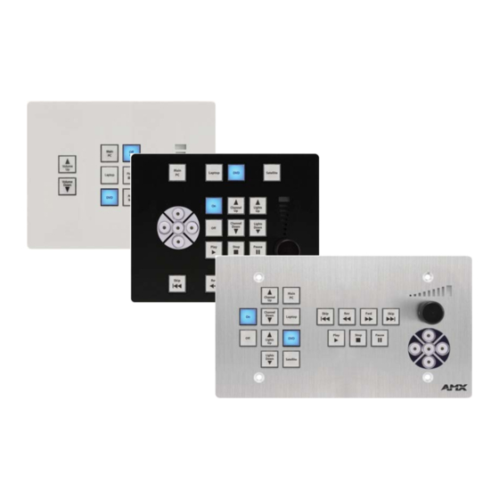
NOVARA ControlPads are designed to be easily configurable allowing control of equipment by RS232 commands and IR. The ControlPads are configured using the AMX DCS Device Configuration Software software application, available for download from www.amx.com. Refer to the Device Configuration Software section on page 25 for more information. CP-3008 CP-3017-NA... -
Page 8: Product Specifications
• Relative humidity: 5% to 85%, non-condensing Included Accessories: • Power Supply, 90-240VACIN, 12VOUT, 500MA (24-5791-SA) • Pre-printed labels (40-0087) Other AMX Equipment: • CP-RMS, RMS Gateway Module (FG1310-01) • CC-NIRC, NetLinx IR Emitter (FG10-000-11) Certifications: FCC Class B, CE, UL, CB Scheme... -
Page 9: Cp-3017-Tr-Us & -Na
1A maximum or 28V @ 1A maximum • LAN - 1 RJ-45 connector for LAN connectivity. • Reset - 1 pinhole pushbutton for factory reset (CP-3017-TR-US only, see for location of Reset button access). Supported Baud Rates: Up to 115200 Dimensions (HWD): 4 11/16"... - Page 10 28V @ 1A max. • LAN - 1 RJ-45 connector for LAN connectivity. • Reset Button - 1 pinhole button for factory reset (CP-3017-TR-US only, see FIG. 4 on page 7 for location of Reset button access). Supported Baud Rates:...
-
Page 11: Mounting Specifications - 6-Button Controlpads
NOVARA 3000 Series ControlPads Mounting Specifications - 6-Button ControlPads CP-3006 CP-3006 6-button keypads mount onto standard 1 gang US, UK, or EU back boxes. FIG. 2 CP-3006 dimensions Novara 3000 Series ControlPads Instruction Manual... -
Page 12: Mounting Specifications - 8-Button Controlpads
NOVARA 3000 Series ControlPads Mounting Specifications - 8-Button ControlPads CP-3008 CP-3008 8-button keypads mount onto standard 2 gang US, UK, or EU back boxes. FIG. 3 CP-3008 dimensions Novara 3000 Series ControlPads Instruction Manual... -
Page 13: Mounting Specifications - 17-Button Controlpads
NOVARA 3000 Series ControlPads Mounting Specifications - 17-Button ControlPads CP-3017-TR-US CP-3017-TR-US 17-button keypads mount onto standard 4 gang US back boxes. Reset button access FIG. 4 CP-3017-TR-US dimensions Novara 3000 Series ControlPads Instruction Manual... -
Page 14: Cp-3017-Na
NOVARA 3000 Series ControlPads CP-3017-NA CP-3017-NA 17-button keypads mount onto standard 2 gang US, UK, or EU back boxes. FIG. 5 CP-3017-NA dimensions Novara 3000 Series ControlPads Instruction Manual... -
Page 15: Button Layout
NOVARA 3000 Series ControlPads Button Layout This section displays the button layout for each type of ControlPad. CP-3006 FIG. 6 CP-3006 button layout CP-3008 FIG. 7 CP-3008 button layout CP-3017-NA FIG. 8 CP-3017-NA button layout Novara 3000 Series ControlPads Instruction Manual... -
Page 16: Cp-3017-Tr-Us
NOVARA 3000 Series ControlPads CP-3017-TR-US Reset button access FIG. 9 CP-3017-TR-US button layout Novara 3000 Series ControlPads Instruction Manual... -
Page 17: Wiring And Device Connections
Wiring and Device Connections Wiring and Device Connections Overview This section describes the device connectors and ports available on each type of NOVARA 3000-series ControlPad. Here you can find wiring and electrical capacities for each type of connector. FIG. 10 displays the rear panel of the CP-3006: Power POWER IR Port... -
Page 18: Rear Panel Components
Wiring and Device Connections The CP-3017-NA ControlPad has an identical rear panel layout as the CP-3008 except that the CP-3017-NA contains a third RS-232 port. FIG. 12 displays the rear panel of the CP-3017-TR-US: RS232 ports Relay ports Power I/O port... -
Page 19: Relays
Wiring and Device Connections RELAYS You can connect up to two independent external relay devices to the Relay connectors on the device. Connectors labeled A are for Common and B are for Output (FIG. 15). FIG. 15 RELAYS connectors Each relay is isolated and normally open. -
Page 20: Lan (Rj-45)
Wiring and Device Connections Output only port. Output voltage is as follows: = +3.3 V +/- 0.3 V @ 13 mA maximum = 0 V +/- 0.3 V @ 13 mA maximum The IR/Serial connector wiring specifications are listed in the following table. IR Connector Wiring Specifications (per Port) IR connections Signal... -
Page 21: Resetting The Controlpad
Wiring and Device Connections Resetting the ControlPad Each ControlPad features a pinhole Reset pushbutton on the rear on the unit for factory reset. To reset the ControlPad, press and hold in the Reset pushbutton for 10 seconds, then release it. The ControlPad will reset. During factory reset, the backlight turns off for all buttons, but all buttons should be back online after 1-2 minutes. -
Page 22: Button Functions
You can create a CP-3000 script for each button on the remote to perform a specific task when pressed. The buttons can be programmed by using AMX DCS software to program a virtual button. Each button has a corresponding IR remote code. -
Page 23: Ps-Poe-Ex0.9 Poe Extractor
Wiring and Device Connections PS-PoE-EX0.9 PoE Extractor The PS-PoE-EX0.9 PoE Extractor (FG423-85) (FIG. 22) is a power extractor module that delivers regulated DC power for any secondary device that is not Power-over-Ethernet (PoE) capable. It allows multiple PoE devices to run over a single power over Ethernet. -
Page 24: Connection
Wiring and Device Connections Connection The PS-PoE-EX0.9 PoE Extractor converts a LAN connector PoE source into a data-only LAN output and a voltage- only output via a standard DC connector. Use standard Cat5 cables and the provided power connector to connect the PoE Extractor to your ControlPad. -
Page 25: Button Labeling
Button Labeling Button Labeling Overview NOVARA ControlPads and KeyPads come with a set of clear plastic Key Caps, which are designed to fit tightly over the pushbuttons, and allow you to place a label on each button according to the requirements of your particular installation. NOVARA ControlPads and KeyPads also come with a pre-printed acetate sheet with a range of 50 (pre-cut) button label inserts. - Page 26 Button Labeling Key Cap - tilted so that the bottom of the Cap is placed on the bottom At this point, do not allow the clips of the pushbutton first on the sides of the Key Cap to engage Clip Clip Pushbutton on keypad Press the top of the Key Cap...
-
Page 27: Removing/Replacing Button Labels
Use a Torx driver with a T8 tip for the Torx screws; use a Phillips-head screwdriver for the Phillips-head screws. For CP-3006 and CP-3017-TR-US ControlPads, the screws attach through the holes in the faceplate. See the CP-3008 Reassembly section on page 22, the CP-3017-NA Reassembly section on page 22, and the CP-3017-TR-US Reassembly section on page 23 for visual demonstrations of how to reassemble each type of ControlPad. -
Page 28: Cp-3008 Reassembly
Button Labeling CP-3008 Reassembly FIG. 29 CP-3008 reassembly CP-3017-NA Reassembly FIG. 30 Reassembling a CP-3017-NA ControlPad Novara 3000 Series ControlPads Instruction Manual... -
Page 29: Cp-3017-Tr-Us Reassembly
Button Labeling CP-3017-TR-US Reassembly FIG. 31 CP-3017-TR-US reassembly Novara 3000 Series ControlPads Instruction Manual... - Page 30 Button Labeling Novara 3000 Series ControlPads Instruction Manual...
-
Page 31: Device Configuration Software
Device Configuration Software Device Configuration Software Overview You can configure Novara ControlPads and KeyPads using the AMX DCS software application, available for download from www.amx.com (FIG. 32). FIG. 32 AMX DCS Main screen The AMX DCS application allows the ControlPad to perform various functions such as RS232/IR control, button feedback, delay time, and relay control. -
Page 32: Setting Your Bonjour Preference
Device Configuration Software You may experience scaling issues with the AMX DCS user interface if you use Large or Extra Large fonts with a low resolution display. Adjusting your resolution to a standard DPI setting should resolve these issues. Setting Your Bonjour Preference Bonjour is a zero-configuration networking client that allows you to detect the IP addresses of any ControlPads on a local area network. -
Page 33: Project Device Configuration
The project device configuration establishes the layout of all devices in the system. When you open an existing project device configuration, AMX DCS detects all devices on the network. Any devices found appear in the Devices Found on Network area. You can use these devices to create a layout of devices, separating each by project or location. You can create your device layout in the Device Configuration Layout &... -
Page 34: Modifying A Controlpad In The Device Layout
A tagged device can be programmed or receive a firmware upgrade. Any firmware upgrades or device programming you perform in the AMX DCS window only apply to the tagged devices in the Project Device Configuration. Select a device then click the Tag button to tag the device. -
Page 35: Creating A New Project
If you have a CP-3006 with a serial number (located under the barcode) of 123456APX78A0001, the hostname and the device name that will be used by its Bonjour beacon will be AMX-CP-3006-123456APX78A0001. For models with a designation such as CP-3017-TR, the hostname will include the -TR (e.g. -
Page 36: Adding A Node To The Device Layout
A tagged device can be programmed or receive a firmware upgrade. Any firmware upgrades or device programming you perform in the AMX DCS window only apply to the tagged devices in the Project Device Configuration. Select a device then click the Tag button to tag the device. Selecting a Project or Location then clicking the Tag button shall tag all sub-devices. - Page 37 Device Configuration Software The following table lists the options for each section of the Configure Global Device Settings window: Configure Global Device Settings Window Options Network Enable DHCP Enables DHCP on all devices when checked. This option is checked by default. This option is checked by default.
-
Page 38: Enabling The Http Web Server
Device Configuration Software Configure Global Device Settings Window Options (Cont.) Enable HTTP Web Server Enables the HTTP web server on all devices when checked. This option is unchecked by default. This option enables access to web pages for all devices. See the Web Console section on page 63 for more information on the web pages. -
Page 39: Device Interface
Device Interface AMX DCS programs the buttons on your ControlPad. Using the device interface and the options provided, you can program each individual button, including the navigational pad buttons (#18-22), and the volume knob button (#23). You can also program events for the two directional turns of the volume knob button. -
Page 40: Device Setup
While the Script window is open, you cannot access the script in the AMX DCS window. An Expanded View Active message appears in the Scripting area when the Script window is open. - Page 41 Device Configuration Software Scripting Options (Cont.) Copy Click to copy the selected events into memory. This button appears grayed-out until you select an event within the script. These events can be viewed by clicking Clipboard. Paste Click to place the events on the current clipboard into the script. The events are inserted at the end of the script.
-
Page 42: Setup
Perform these steps to set the backlight color of a button: In the AMX DCS window, click the plus sign (+) beside Setup in the Content area. A list of setup options appear. Click Button Backlight. The Button Backlight options appear (FIG. 44). -
Page 43: Button Behavior
You can choose from Normal, Bank, and Toggle. Selecting Bank activates the Bank Assign option. Selecting Toggle activates the Max # of Toggles option. Selecting the Bank or Toggle options also activates the respective Bank Level or Toggle Level option in the Inputs area on the AMX DCS window. -
Page 44: Volume Control
Perform these steps to set the volume control for a device: In the AMX DCS window, click the plus sign (+) beside Setup in the Content area. A list of setup options appear. Click Volume Control. The Volume Control options appear (FIG. 48). -
Page 45: Interrogation
Perform these steps to assign a device to a ControlPad: In the AMX DCS window, click the plus sign (+) beside Setup in the Content area. A list of setup options appear. Click Interrogation. The Device Interrogation options appear (FIG. 49). - Page 46 Device Library. See the Adding a Device to the Device Library section on page 56 for more information. In the AMX DCS window, click Tag Data to open the Device Interrogation window (FIG. 51) and view the details of the device.
-
Page 47: Feedback
Perform these steps to change the custom request and status names for RMS: In the AMX DCS window, click the plus sign (+) beside Setup in the Content area. A list of setup options appear. Click Interrogation. The Device Interrogation options appear (FIG. 49). -
Page 48: Volume Bar
Note: You cannot turn off the brightness level by setting the level to 0. Perform the following steps to set button feedback: In the AMX DCS window, click the plus sign (+) beside Feedback in the Content area. A list of feedback options appear. - Page 49 Click to open the DCS Device Library window. Using this window, you can select an RS232 device to program. Perform these steps to an RS232 event to a script: In the AMX DCS window, click RS232. The RS232 options appear (FIG. 55). Click Select Device to open the DCS Device Library dialog (FIG. 56). FIG. 56 DCS Device Library dialog Select the manufacturer of the device you want to program from the Make options menu.
- Page 50 56 and the Importing a Device Library section on page 57 for more information. Click Load Devices to close the dialog and return to the AMX DCS window. You should now see the Device Model and Function menus populated with one or more options.
-
Page 51: Relay
Click Load IR File for Selected Port. An Open dialog appears with which you can navigate to the location of an AMX IR file (.irl) containing information about your IR device. After you have selected the appropriate file, click Select the IR port the device is connected to from the Port options menu. -
Page 52: Delay
Perform these steps to set a delay in a script: In the AMX DCS window, click Delay. The Delay options appear (FIG. 60). Use the Minutes and Seconds sliders to set the amount of time for the delay. -
Page 53: Bank Enable
Perform these steps to set a button lockout: In the AMX DCS window, click Lockout Buttons. The Lockout Buttons options appear (FIG. 61). From the Unlock Method options menu, select whether you want the passcode to be a sequential order of button presses (Sequence) or a collection of button to be pressed simultaneously (Multi-Press). -
Page 54: Advance Toggle
RMS, create a virtual button that contains all the events you want to run, and if you want to change the toggle level, use the advance toggle level to X script function. In the AMX DCS window, click Advance Toggle. The Advance Toggle options appear (FIG. 64). FIG. 64 Advance Toggle options The following procedure provides an example of how to use the Advance Toggle option. - Page 55 Device Configuration Software Select Red from the Color menu, and select 1 from the Toggle Level menu on the right side of the window (FIG. 65). Toggle Level menu FIG. 65 Toggle Level menu Click Add to add the event to the script. Select Green from the Color menu, and select 2 from the Toggle Level menu on the right side of the window.
-
Page 56: Button Actions And Events
Creating a Custom Name for a Button You can use AMX DCS to create customized buttons for RMS. Perform these steps to create a custom name for a button: In the Button area, press Add Custom Name. The Custom Assigned Button Name dialog opens (FIG. 67). -
Page 57: Inputs
Device Configuration Software FIG. 67 Custom Assigned Button Name dialog Enter a device ID number within the range of 2000-65536 in the RMS Unique ID field. If you enter a number outside the device ID range, an error message appears. Enter a name for the button in the Assigned Name field. -
Page 58: Creating A Schedule Script
FIG. 71 Schedule Properties window Enter a name for the schedule in the Name field. This name will appear in the schedule menu on the AMX DCS window after you save the schedule. Click the Once or Repeat option button to indicate how often you want the script to execute. Depending on which option you choose, perform one of the following: ... -
Page 59: Programming A Device
Use the Hours and Minutes menus to indicate the length of the timeout. Click Save to return to the AMX DCS window. Select the timeout from the Timeout menu and create a script. When you program the device, the script will execute after the specified amount of time elapses without any activity on the ControlPad. -
Page 60: Device Library Manager
Tag any devices you want to program. You can tag as many devices as needed. On the AMX DCS window, build a script using the device interface and the available options. Click Program Devices. The Programming Device(s) Monitor dialog opens and displays the list of devices to be programmed. - Page 61 Allows you to import Novara or Solecis legacy library files (one-by-one) and add their device definitions to the library. You can also import a previously exported.xml library file. Click to open a web browser which navigates to www.amx.com so you can download a device library file.
-
Page 62: Device Interrogation Formulas
Save all changes to the device library. Clear and re-select the device on the interrogation feature in the AMX DCS window. Select Compile Scripts from the Tools menu. If the pop-up says "Compiled Successfully" it means the interrogation formulas follow the correct syntax. If an error appears, it indicates which status request or formula has an error. -
Page 63: Modifying Devices In The Device Library
Device Configuration Software Click Save to save the Device Library. DCS will add default fields when you create a new custom library file. Modifying Devices in the Device Library To modify a device's connection and command information, perform the following steps: Select the device from the Device Selection tree. -
Page 64: Ascii To Hex Tool
Device Configuration Software Right-click the device with undefined fields, and select Rename Device(s). The Rename Device Libraries dialog opens (FIG. 78). FIG. 78 Rename Device Libraries dialog Enter the appropriate information in the undefined fields. Click Rename. The Rename Device Libraries dialog closes, and you can now import the device library. ASCII to Hex Tool Use the ASCII to Hex tool to convert ASCII text to a hexadecimal value for device commands. -
Page 65: Test Command Tool
The following options appear in this window: Test Command Tool Options Available COM Port(s) The available ports on the connected device. Click the Show COM ports and Connected AMX Devices button to refresh the list of available ports. Show COM Ports and Click to refresh the list of available COM ports. -
Page 66: Updating Firmware
You must use a Novara CP3000 Firmware Data File (.out) to upgrade the firmware through AMX DCS software. The latest firmware files can be found at the Tech Center at www.amx.com. Perform these steps to update the firmware on your ControlPad: Open the Device Configuration &... - Page 67 Device Configuration Software When you upgrade a ControlPad from a 1.0 version of firmware to a 1.2 version of firmware, the firmware must be upgraded two times. DCS normally prompts you to perform both upgrades. If you do not run the upgrade two times, the Web Console will not be available.
- Page 68 Device Configuration Software Novara 3000 Series ControlPads Instruction Manual...
-
Page 69: Web Console
Changing the Image Logo on the Web Pages AMX DCS contains a feature which enables you to add a logo or image file (.jpg, .gif, .png) which appears on each page. The image cannot be greater than 7 kilobytes in size. If the file is greater than 7 kilobytes, you will receive a notification that the file is too large and must be reduced in size before you can use it. -
Page 70: Device Information Page
Web Console Device Information Page The Device Information page displays information about the device such as device name and IP address. You cannot change any of the information on this page. However, you can reboot the ControlPad by clicking Reboot. FIG. 83 displays the Device Information page. -
Page 71: Rms Configuration
RMS Configuration RMS Configuration Overview ® NOVARA 3000-series ControlPads can connect to a Resource Management Suite (RMS) server to view online status, execute control functions, create macros containing those control functions, and schedule the execution of the macros. Connecting to RMS involves installing a proxy, called the CP-RMS application, directly onto the RMS server or on a PC. The proxy serves as a gateway between the ControlPads and the RMS server. -
Page 72: Installing The Cp-Rms Proxy
RMS Configuration Installing the CP-RMS Proxy Perform these steps to install the CP-RMS proxy: Double-click the CPRMS.msi file to open the AMX CP-RMS Service Setup Wizard (FIG. 85). FIG. 85 AMX CP-RMS Service Setup Wizard Click Next. The next screen in the Installation Wizard enables you to change the installation folder (FIG. 86). Click Browse to navigate to a new folder, or click Next to accept the default location. -
Page 73: Editing The Configuration File
ControlPads which the proxy uses zero configuration to discover. You can configure this value on the ControlPads in the global or device settings using AMX DCS. See the Configuring Global Settings section on page 30 for more information. -
Page 74: Rms Control Functions And Macros
When a ControlPad connects to RMS, all physical and virtual buttons that have been programmed properly with scripts and Button Assigned Names using AMX DCS display as available control functions in RMS (see the Button Actions and Events section on page 50 for more information). These control functions are available for inclusion in macros. You can schedule the macros to execute by using the RMS Internal Scheduler or an external scheduler. - Page 75 RMS Configuration Novara 3000 Series ControlPads Instruction Manual...
- Page 76 - Schedules and registration for any AMX University course - Travel and hotel information - Your individual certification requirements and progress 3000 RESEARCH DRIVE, RICHARDSON, TX 75082 USA • 800.222.0193 • 469.624.8000 • 469-624-7153 fax • 800.932.6993 technical support • www.amx.com...
Need help?
Do you have a question about the CP-3017-TR-US and is the answer not in the manual?
Questions and answers