Table of Contents
Advertisement
Quick Links
Advertisement
Table of Contents

Subscribe to Our Youtube Channel
Related Manuals for Icom IC-M502AW


Summary of Contents for Icom IC-M502AW
- Page 1 INSTRUCTION MANUAL VHF MARINE TRANSCEIVER iM502A...
-
Page 2: Foreword
Icom, Icom Inc. and the logo are registered trademarks ❍ Rugged waterproof construction of Icom Incorporated (Japan) in the United states, the United Kingdom, Germany, France, Spain, Russia and/or other coun- ❍ NMEA Input/Output tries. COMMANDMIC is a registered trademark of Icom Incorporated (Japan) in the United states. -
Page 3: In Case Of Emergency
IN CASE OF EMERGENCY NOTE If your vessel requires assistance, contact other vessels and A WARNING STICKER is supplied with the transceiver. the Coast Guard by sending a distress call on Ch 16. To comply with FCC regulations, this sticker must be affixed in such a location as to be readily seen from the operating con- USING CHANNEL 16 trols of the radio as in the diagram below. -
Page 4: Radio Operator Warning
RADIO OPERATOR WARNING Icom requires the radio operator to meet the FAILURE TO OBSERVE THESE LIMITS MAY ALLOW FCC Requirements for Radio Frequency Expo- THOSE WITHIN THE MPE RADIUS TO EXPERIENCE RF sure. An omnidirectional antenna with gain not RADIATION ABSORPTION WHICH EXCEEDS THE FCC greater than 9 dBi must be mounted a minimum MAXIMUM PERMISSIBLE EXPOSURE (MPE) LIMIT. -
Page 5: Table Of Contents
TABLE OF CONTENTS FOREWORD ..........i 6 DSC OPERATION ....14 – 35 10 TROUBLESHOOTING ....48 I MMSI code programming ..... 14 IMPORTANT ..........i 11 CHANNEL LIST ......49 I DSC individual ID ......14 IN CASE OF EMERGENCY ...... ii 12 SPECIFICATIONS AND I Position and Time programming ... -
Page 6: Precaution
Place the transceiver in a secure place to avoid inadvertent CAUTION: use by children. Changes or modifications to this device, not ex- pressly approved by Icom Inc., could void your authority to BE CAREFUL! The transceiver and optional HM-127 em- operate this device under FCC regulations. -
Page 7: Operating Rules
OPERATING RULES D D PRIORITIES (2) OPERATOR’S LICENSE A Restricted Radiotelephone Operator Permit is the license • Read all rules and regulations pertaining to priorities and most often held by small vessel radio operators when a radio keep an up-to-date copy handy. Safety and distress calls is not required for safety purposes. -
Page 8: Panel Description
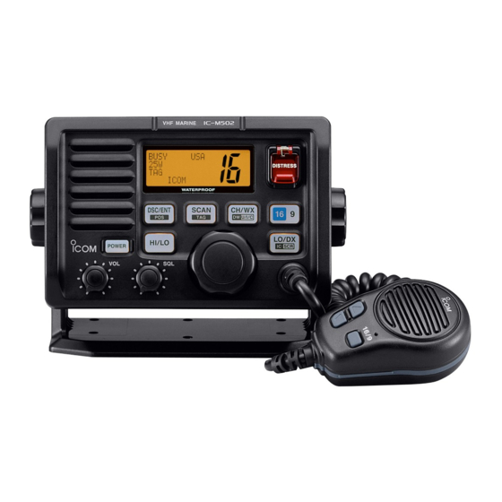
PANEL DESCRIPTION I Front panel q VOLUME CONTROL ] (p. 8) Adjusts the audio level. Function Speaker display w POWER KEY POWER POWER Push to turn the transceiver power ON or OFF. iM502 VHF MARINE e SQUELCH CONTROL ] (p. 8) DISTRESS Sets the squelch threshold level. - Page 9 PANEL DESCRIPTION y ATTENUATOR/INTERCOM/SCRAMBLER KEY i DISTRESS KEY DISTRESS DISTRESS Transmits Distress call when pushed for 5 sec. (p. 18) LO/DX LO/DX SCR) SCR) ➥ Toggles the Attenuator function ON or OFF when o CHANNEL/DUALWATCH/TRI-WATCH KEY pushed momentarily. (p. 8) CH/WX CH/WX U/I/C)
-
Page 10: I Function Display
PANEL DESCRIPTION I Function display q BUSY/TRANSMIT INDICATOR (p. 8) ➥ “BUSY” appears when receiving a signal or when the squelch opens. BUSY ➥ “TX” appears while transmitting. CALL w POWER INDICATOR (p. 8) ➥ “25W” appears when high power is selected. CALLING ➥... -
Page 11: I Microphone
PANEL DESCRIPTION I Microphone y DUPLEX INDICATOR (p. 7) Appears when a duplex channel is selected. • Duplex channel has a different TX and RX frequency. Speaker u CHANNEL NUMBER READOUT ➥ Indicates the selected operating channel number. Microphone “A” appears when a simplex channel is selected. “b” ap- pears when a receive only channel for a Canadian chan- nel group is selected. -
Page 12: Basic Operation
BASIC OPERATION I Channel selection D D Channel 16 D D Channel 9 (Call channel) Channel 16 is the distress and safety channel. It is used for Each regular channel group has a separate leisure-use call establishing initial contact with another station and for emer- channel. - Page 13 BASIC OPERATION D D U.S.A., Canadian and International channels D D Weather channels There are 57 U.S.A., 61 Canadian and 57 International chan- There are 10 weather channels. Used for monitoring weather nels. These channel groups may be specified for the operat- channels from the NOAA (National Oceanographic and At- ing area.
-
Page 14: I Receiving And Transmitting
BASIC OPERATION I Receiving and transmitting ∗ CAUTION: u Push and hold Transmitting without an antenna may dam- ] to transmit, then speak into (Mi- age the transceiver. crophone). • “TX” appears. q Push • Channel 70 cannot be used for transmission other than DSC. ] to turn power ON. -
Page 15: I Call Channel Programming
BASIC OPERATION I Call channel programming I Channel comments Call channel is used to select Channel 9 (default), however, Memory channels can be labeled with alphanumeric com- you can program the call channel with your most often-used ments of up to 10 characters each. channels in each channel group for quick recall. -
Page 16: I Optional Voice Scrambler Operation
BASIC OPERATION I Optional Voice scrambler operation D D Activating the Scrambler D D Programming scrambler codes The optional Voice scrambler provides private communica- There are 128 or 32 codes (0 to 127 or 1 to 32) available for tions. In order to receive or send scrambled transmissions programming when the optional UT-98 or UT-112 is installed. -
Page 17: Dualwatch/Tri-Watch
DUALWATCH/TRI-WATCH I Description I Operation q Select Dualwatch or Tri-watch in Set mode. (p. 39) Dualwatch monitors Channel 16 while you are receiving an- w Select the desired operating channel. other channel; Tri-watch monitors Channel 16 and call chan- e Push nel while receiving another channel. -
Page 18: Scan Operation
SCAN OPERATION I Scan types Scanning is an efficient way to locate signals quickly over a Set the tag channels (scanned channel) before scanning. wide frequency range. The transceiver has Priority scan and Clear the tag channels which inconveniently stop scanning, Normal scan. -
Page 19: I Setting Tag Channels
SCAN OPERATION I Setting tag channels I Starting a scan For more efficient scanning, add desired channels as tag Set scan type (Priority or Normal scan) and scan resume channels or clear tag channels for unwanted channels. Chan- timer in advance using Set mode. (p. 39) nels not tagged will be skipped during scanning. -
Page 20: Dsc Operation
DSC OPERATION I MMSI code programming I DSC individual ID A total of 40 DSC address IDs can be programmed and The 9-digit MMSI (Maritime Mobile Service Identity: DSC self named with up to 10 characters. ID) code can be programmed at power ON. D D Programming Address ID/Group ID This function is not available when the MMSI code has q Push... - Page 21 DSC OPERATION r Set the individual ID and ID name. D D Deleting Address ID/Group ID • Edit the 9 digits of the appropriate distress ID by using CHAN q Push CHAN ] to enter the DSC menu. DSC/ENT DSC/ENT w Rotate ] to select “Set up,”...
-
Page 22: I Position And Time Programming
DSC OPERATION I Position and Time programming r Edit the digit of your longitude data by using A distress call should include the ship’s position and time. If CHANNEL CHANNEL • Push ] or ] for cursor movement. no GPS is connected, your position and UTC (Universal Time CH/WX] CH/WX SCAN... -
Page 23: I Position/Time Indication
➥ “??” may blink instead of position and time indications A GPS receiver appropriate for the IC-M502A is not supplied from Icom. A GPS receiver with NMEA0183 ver. 2.0 or 3.01 when the GPS data is invalid, or has not been manually format is required for position indication. -
Page 24: I Distress Call
DSC OPERATION I Distress call A Distress call should be transmitted, if in the opinion of the Distress Master, the ship or a person is in distress and requires imme- Completed diate assistance. Wait for ACK NEVER USE THE DISTRESS CALL WHEN r After receiving the acknowledgment, reply using the mi- YOUR SHIP IS NOT IN AN EMERGENCY. - Page 25 DSC OPERATION D D Normal call When a GPS receiver (NMEA0183 ver. 2.0 or 3.01) is con- nected, next steps r, t (Current position/time program- The nature of the Distress call should be included in the Dis- ming) do not appear. Go to step y. (next page) tress call.
- Page 26 DSC OPERATION ➥ A distress alert contains; y Push ] for 5 sec. to transmit the Distress call. DISTRESS DISTRESS • Kind of distress : Selected nature of the distress. Set is OK • Position data: GPS or manual input position data held for 23.5 hrs or until the power is turned OFF.
-
Page 27: I Transmitting Dsc Calls
DSC OPERATION I Transmitting DSC calls D D Transmitting Individual call r Rotate The Individual call function allows you to transmit a DSC sig- ] to select a desired intership channel CHANNEL CHANNEL nal to a specific ship only. or “Manual Input,” push DSC/ENT DSC/ENT •... - Page 28 DSC OPERATION y After transmitting the Individual call, standby on Channel D D Transmitting Individual acknowledgement 70 until an acknowledgement is received. Transmit an acknowledgement (‘able to comply’ or ‘unable to comply’) when an Individual call for you is received. Individual Completed q Push...
- Page 29 DSC OPERATION r Rotate u After the Individual acknowledgement has been transmit- ] to select an acknowledgement CHANNEL CHANNEL “Able” or “Unable,” push ted, the display changes to the channel specified by the DSC/ENT DSC/ENT calling station, automatically. Comply ˘Able INDV ACK Unable Completed...
- Page 30 DSC OPERATION D D Transmitting Group call r Rotate ] to select a desired intership channel The Group call function allows you to transmit a DSC signal CHANNEL CHANNEL or “Manual Input,” push to a specific group only. DSC/ENT DSC/ENT •...
- Page 31 DSC OPERATION D D Transmitting All Ships call r After the All Ships call has been transmitted, the display Large ships use Channel 70 as their ‘listening channel.’ When changes to Channel 16 automatically. you want to announce a message to these ships, use the ‘All Ships Call’...
- Page 32 DSC OPERATION D D Transmitting Position Request call r Push ] to transmit the Position Request call. Transmit a Position Request call when you want to know a DSC/ENT DSC/ENT specific ship’s current position, etc. To Call, [DSC/ENT] q Push ] to enter the DSC menu. To Cancel DSC/ENT DSC/ENT...
- Page 33 DSC OPERATION D D Transmitting Position Report call When a GPS receiver (NMEA0183 ver. 2.0 or 3.01) is con- nected, next steps r, t (Current position/time program- Transmit a Position Report call when you want to announce ming) do not appear. Go to step y. (next page) your own position to a specific ship and to get answer, etc.
- Page 34 DSC OPERATION y Push D D Transmitting Position Reply call ] to transmit the Position Report call. DSC/ENT DSC/ENT Transmit a Position Reply call when a Position Request call is To Call, received. [DSC/ENT] To Cancel [other] q When a Position Request call is received, the following in- dication is displayed.
-
Page 35: I Receiving Dsc Calls
DSC OPERATION I Receiving DSC calls D D Receiving an Individual call While monitoring Channel 70 and an Individual call is re- D D Receiving a Distress call ceived: ➥ The emergency alarm or beeps sound depending on the While monitoring Channel 70 and a Distress call is received: ➥... - Page 36 DSC OPERATION D D Receiving an All Ships call D D Receiving a Distress Relay acknowledgement While monitoring Channel 70 and an All Ships call is received: While monitoring Channel 70 and a Distress Relay acknowl- ➥ Emergency alarm sounds when the category is ‘Distress’ edgement is received: ➥...
- Page 37 DSC OPERATION D D Receiving a Position Request call D D Receiving a Position Report call While monitoring Channel 70 and a Position Request call is While monitoring Channel 70 and a Position Report call is re- received: ceived: ➥ “Received POS Request” appears in the display. ➥...
-
Page 38: I Received Messages
DSC OPERATION I Received messages The transceiver automatically stores up to 20 distress mes- Sel DTRS MSG sages and 20 other messages. The messages can be used ˘123123123 as an assistance to the logbook. 111222345 Chuck 3 q Push ] to select the DSC menu. DSC/ENT DSC/ENT e Rotate... - Page 39 DSC OPERATION D D Other messages e Rotate q Rotate ] to scroll the message. select “Other,” push CHANNEL CHANNEL CHANNEL CHANNEL • The stored message has various information and depending on DSC/ENT DSC/ENT the type of distress calls. Sel Messege Distress All Ships < Tom...
-
Page 40: I Dsc Set Mode
DSC OPERATION I DSC Set mode D D Add Address ID r Set the offset time from the UTC (Universal Time Coordi- (See p.14 for detail) nated) time. D D Delete Address ID (See p.15 for detail) • Edit the digit of offset time by using CHANNEL CHANNEL - Push... - Page 41 DSC OPERATION D D MMSI code check The programmed 9-digit MMSI (DSC self ID) code can be checked in DSC Set mode. q Push ] to enter the DSC menu. DSC/ENT DSC/ENT w Rotate ] to select “Set up,” push CHANNEL CHANNEL DSC/ENT...
-
Page 42: Other Functions
OTHER FUNCTIONS I Intercom operation The optional Intercom function allows you to talk to the deck from the cabin. The optional HM-127 REMOTE-CONTROL MI- is required for Intercom operation. CROPHONE Intercom TALK Connect an optional HM-127 as described on pgs. 43, 65. •... -
Page 43: I Microphone Lock Function
OTHER FUNCTIONS I Microphone lock function I Display backlighting The Microphone lock function electrically locks the The function display and keys can be backlit for better visibil- ] keys on the supplied microphone. This prevents ity under low light conditions. 16/9 16/9 accidental channel changes and accidental function access. -
Page 44: Set Mode
SET MODE I Set mode programming q Turn power OFF. Set mode is used to change the conditions of the trans- w While pushing ] , turn power ON to enter Set mode. ceiver’s functions: scan mode (Normal or Priority), scan re- e After the display appears, release sume timer, weather alert, Dualwatch/Tri-watch selection, r Push... -
Page 45: I Set Mode Items
SET MODE I Set mode items D D Scan mode D D Weather alert The transceiver has 2 scan modes: Normal scan and Priority A NOAA broadcast station transmits a Weather alert tone be- scan. Normal scan searches all tag channels in the selected fore important weather information. - Page 46 SET MODE D D DSC watch D D Internal speaker DSC watch monitors Channel 70 while you are receiving an- When an external speaker is connected and the transceiver’s other channel. internal speaker is not required, the speaker on the trans- If a distress signal is received on Channel 70, the transceiver ceiver and microphone can be deactivated.
- Page 47 SET MODE D D Attenuation level D D Scrambler type (Appears when a scrambler unit is installed) This item sets the receive attenuation level for the Attenuator function from 3 levels. When an optional scrambler unit is installed, the scrambler type can be selected in Set mode depending on dealer set- Set Mode ting.
-
Page 48: Connections And Maintenance
CONNECTIONS AND MAINTENANCE I Supplied accessories I Antenna The following accessories are supplied: Qty. A key element in the performance of any communication sys- q Mounting bracket ............1 tem is an antenna. Ask your dealer about antennas and the w Microphone hanger ............ -
Page 49: I Connections
CONNECTIONS AND MAINTENANCE I Connections r NMEA IN (Red)/NMEA OUT (White) JACKS Connects to a GPS receiver for position and time indica- tions. • An NMEA0183 ver. 2.0 or 3.01 (sentence formatters RMC, GGA, GNS, GLL) compatible GPS receiver is required. Ask your dealer about suitable GPS receivers. -
Page 50: I Mounting The Transceiver
CONNECTIONS AND MAINTENANCE I Mounting the transceiver D D Using the supplied mounting bracket • OVERHEAD MOUNTING The universal mounting bracket supplied with your transceiver allows overhead or onboard mounting. • Mount the transceiver securely with the 4 supplied screws (M5 ×... - Page 51 CONNECTIONS AND MAINTENANCE D D Using the optional MB-75 r Attach the clamps on either side of the IC-M502A. • Make sure that the clamps align parallel to the IC-M502A’s body. An optional MB-75 is available for mounting FLUSH MOUNT the transceiver to a flat surface such as an instrument panel.
-
Page 52: I Optional Unit Installation
CONNECTIONS AND MAINTENANCE I Optional unit installation e Plug an optional unit (UT-98 or UT-112) to J3 on the MAIN unit as shown below. CAUTION: DISCONNECT the DC power cable from the transceiver before performing any work on the transceiver. Otherwise, there is danger of electric shock and/or equip- ment damage. -
Page 53: I Dimensions
CONNECTIONS AND MAINTENANCE I Dimensions 145.0 (5 ⁄ 31.4 53.0 165.0 (6 ⁄ ⁄ ⁄ Unit: mm (inch) -
Page 54: Troubleshooting
TROUBLESHOOTING PROBLEM POSSIBLE CAUSE SOLUTION REF. No power comes ON. • Bad connection to the power supply. • Check the connection to the transceiver. p. 43 No sound comes from • Squelch level is too high. • Set squelch to the threshold point. p. -
Page 55: Channel List
CHANNEL LIST Channel number Frequency (MHz) Channel number Frequency (MHz) Channel number Frequency (MHz) Channel number Frequency (MHz) CAN Transmit Receive CAN Transmit Receive CAN Transmit Receive CAN Transmit Receive 156.050 160.650 19A 156.950 156.950 64A 156.225 156.225 83A 157.175 157.175 156.050 156.050 †... -
Page 56: Specifications And Options
SPECIFICATIONS AND OPTIONS I Specifications D D General D D Transmitter • Frequency coverage • Output power : 25 W / 1 W Transmit 156.025–157.425 MHz • Modulation system : Variable reactance phase Receive 156.050–163.275 MHz modulation • Mode : FM (16K0G3E) •... -
Page 57: I Options
SPECIFICATIONS AND OPTIONS I Options • MB-75 FLUSH MOUNT For mounting the transceiver to a panel. • SP-5 EXTERNAL SPEAKER A large, external speaker for superior audio output. • SP-10 EXTERNAL SPEAKER A compact, external speaker. Features easy installation. • UT-98/ UT-112 VOICE SCRAMBLER UNIT (pgs. 10, 41) Ensures private communications. -
Page 58: Hm-127 Remote-Control Microphone
HM-127 REMOTE-CONTROL MICROPHONE OPTION I Panel description q PTT SWITCH The optional HM-127 remotely controls the IC-M502A and ] (pgs. 8, 57) provides an optional Intercom function. Push and hold to transmit; release to receive. w CHANNEL UP/DOWN KEYS D D Front and side keys ➥... - Page 59 HM-127 REMOTE-CONTROL MICROPHONE r CHANNEL/DUALWATCH/TRI-WATCH KEY y SQUELCH/MONITOR/LOCK KEY MONI ➥ ] sets the squelch threshold level after pushing CH/WX CH/WX U/I/C) U/I/C) ➥ Selects and toggles the regular channels and weather ] . (p. 57) ➥ Push channel when pushed momentarily. (pgs. 6, 7, 56) for 1 sec.
-
Page 60: I Function Display
HM-127 REMOTE-CONTROL MICROPHONE I Function display D D Top keys !8 !7 SCAN TX BUSY CALL WX ALT DUAL P SCAN q POWER KEY [PWR] (pgs. 8, 57) Push for 2 sec. to turn the HM-127 power ON or OFF when the IC-M502A power is turned ON. - Page 61 HM-127 REMOTE-CONTROL MICROPHONE e CHANNEL NUMBER READOUT !0 PRIORITY CHANNEL INDICATOR ➥ Indicates the selected operating channel number. ➥ Indicates a priority channel during Priority scan or “A” appears when a simplex channel is selected. “b” ap- Dual/Tri-watch. (pgs. 11, 13, 60, 61) ➥...
-
Page 62: I Channel Selection
HM-127 REMOTE-CONTROL MICROPHONE I Channel selection D D Channel 16 D D U.S.A., International and Canadian channels q Push q Push ] to select Channel 16. to select a regular channel. CH/WX] CH/WX U/I/C) U/I/C) w Push ] to return to the •... -
Page 63: I Receiving And Transmitting
HM-127 REMOTE-CONTROL MICROPHONE I Receiving and transmitting q Push ] to turn power ON. w Push r Set output power ] , then ] to adjust audio output level. q Turn power ON • Push ] , then push ] to mute any audio noise, if nec- essary. -
Page 64: I Lock Functions
HM-127 REMOTE-CONTROL MICROPHONE I Lock functions I Display backlighting The Lock function electronically locks keys and switches to The function display and keys can be backlit for better visibil- prevent accidental changes and function access from the mi- ity under low light conditions. The backlighting condition can crophone. -
Page 65: I Monitor Function
HM-127 REMOTE-CONTROL MICROPHONE I Monitor function I Call channel programming q Push The monitor function releases the noise squelch mute of the CH/WX several CH/WX U/I/C) U/I/C) microphone only. (An independent noise squelch system is times while pushing ] to select employed.) the desired channel group (USA, ➥... -
Page 66: I Optional Voice Scrambler Operation
HM-127 REMOTE-CONTROL MICROPHONE I Optional Voice scrambler I Dualwatch/Tri-watch operation operation q Push D D Activating the Scrambler ] to select the desired channel. • Push CH/WX] several times while pushing ] to q Select an operating channel, CH/WX U/I/C) U/I/C) select the channel group (USA, INT, CAN), if desired. -
Page 67: I Starting A Scan
HM-127 REMOTE-CONTROL MICROPHONE I Starting a scan I Setting tag channels q While pushing q While pushing ] , push CH/WX several ] , push CH/WX several CH/WX CH/WX U/I/C) U/I/C) U/I/C) U/I/C) times to select the channel group (USA, INT, CAN), if de- times to select the channel group (USA, INT, CAN), if de- sired. -
Page 68: I Set Mode Programming
HM-127 REMOTE-CONTROL MICROPHONE I Set mode programming D D Entering Set mode Set mode is used to change the condition of the transceiver’s functions and the microphone’s own functions: q Turn power OFF. w While pushing , turn power ON. Transceiver’s functions—... -
Page 69: I Intercom Operation
HM-127 REMOTE-CONTROL MICROPHONE I Intercom operation I Channel comments q Push q Push LO/DX] for 1 sec. ] to select a channel to program a channel LO/DX SCR) SCR) to activate the Intercom function. comment. • “IC” appears in the priority channel •... -
Page 70: I Hm-127 Supplied Accessories
HM-127 REMOTE-CONTROL MICROPHONE I HM-127 supplied accessories Accessories included with the HM-127: Qty. q Connection cable (OPC-1000: 6 m; 20 ft) ...... 1 w Mounting base ..............1 e Microphone hanger ............1 r Screws (M3 × 16; tapping) ..........5... -
Page 71: I Installation
HM-127 REMOTE-CONTROL MICROPHONE I Installation w To use the supplied cable as a wall socket, follow the below steps. e Using the mounting base, carefully mark off the 2 spots The optional HM-127 can be connected to the transceiver di- where the cable and screws will be fastened. - Page 72 HM-127 REMOTE-CONTROL MICROPHONE Mounting base 5 mm; ⁄ ˝ 2 mm; ⁄ ˝ Gasket...
-
Page 73: Template
TEMPLATE 165 mm (6 ⁄ 149 mm (5 ⁄ MB-75 4–R11 2 mm; ⁄ HM-127 24 to 27 (d) mm ⁄ to 1 ⁄... - Page 74 A-6301H-1EX Printed in Japan 1-1-32 Kamiminami, Hirano-ku, Osaka 547-0003, Japan © 2003 Icom Inc.
Need help?
Do you have a question about the IC-M502AW and is the answer not in the manual?
Questions and answers