Icom IC-M502 Instruction Manual
Hide thumbs
Also See for IC-M502:
- Instruction manual (62 pages) ,
- Service manual (44 pages) ,
- Operational manual (42 pages)
Advertisement
Quick Links
INSTRUCTION MANUAL
VHF MARINE TRANSCEIVER
iM502
This device complies with Part 15 of the FCC rules. Operation is sub-
ject to the following two conditions: (1) This device may not cause
harmful interference, and (2) this device must accept any interference
received, including interference that may cause undesired operation.
Advertisement

Related Manuals for Icom IC-M502


Summary of Contents for Icom IC-M502
- Page 1 INSTRUCTION MANUAL VHF MARINE TRANSCEIVER iM502 This device complies with Part 15 of the FCC rules. Operation is sub- ject to the following two conditions: (1) This device may not cause harmful interference, and (2) this device must accept any interference received, including interference that may cause undesired operation.
- Page 2 This in- before using the transceiver. struction manual contains important operating instructions for the IC-M502. IN CASE OF EMERGENCY If your vessel requires assistance, contact other vessels and Or, transmit your distress call using digital selective calling on the Coast Guard by sending a distress call on channel 16.
- Page 3 TABLE OF CONTENTS I Position and time programming ..14 IMPORTANT ..........i 12 SPECIFICATIONS AND I Position indication ......15 IN CASE OF EMERGENCY ...... i OPTIONS ......42 – 43 I Distress call ........16 TABLE OF CONTENTS ......ii I Specifications .......
- Page 4 Changes or modifications to this device, not ex- hot when operating continuously for long periods. pressly approved by Icom Inc., could void your authority to operate this device under FCC regulations. Place the transceiver in a secure place to avoid inadvertent NEVER use by children.
- Page 5 OPERATING RULES (2) OPERATOR’S LICENSE PRIORITIES A Restricted Radiotelephone Operator Permit is the license • Read all rules and regulations pertaining to priorities and most often held by small vessel radio operators when a radio keep an up-to-date copy handy. Safety and distress calls is not required for safety purposes.
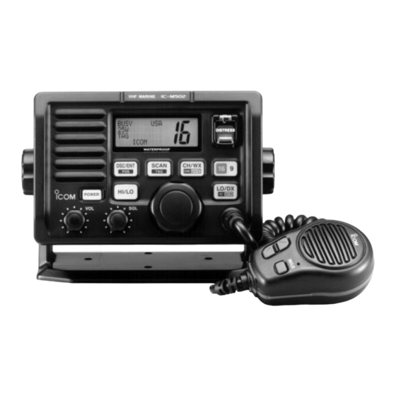
- Page 6 PANEL DESCRIPTION I Panel description q POWER SWITCH [POWER] r TRANSMIT POWER SWITCH [HI/LO] ➥ Toggles high and low power when pushed. (p. 8) Push to toggle the transceiver power ON and OFF. • Some channels are set to low power only. w VOLUME CONTROL [VOL] ➥...
- Page 7 PANEL DESCRIPTION ➥ While pushing [HI/LO], rotate [CHANNEL] to adjust the i DISTRESS SWITCH [DISTRESS] brightness of the LCD and switch backlight. Transmits distress call when pushed for 5 sec. (p. 16) y ATTENUATOR/INTERCOM/SCRAMBLER SWITCH o CHANNEL/DUALWATCH/TRI-WATCH SWITCH [LO/DX•IC•SCR] [CH/WX•DW•U/I/C] ➥...
- Page 8 Count on us! A-5663H-1EX-r Printed in Japan 1-1-32 Kamiminami, Hirano-ku, Osaka 547-0003 Japan © 2000 Icom Inc.
Need help?
Do you have a question about the IC-M502 and is the answer not in the manual?
Questions and answers