Table of Contents
Advertisement
Quick Links
Advertisement
Table of Contents

Related Manuals for Icom IC-M502A


Summary of Contents for Icom IC-M502A
- Page 1 INSTRUCTION MANUAL VHF MARINE TRANSCEIVER iM502A...
-
Page 2: Foreword
We want to take a couple of moments of your time to thank you for making the IC-M502A your radio of choice, and hope you agree with Icom’s philosophy of “technology first.” Many hours of research and devel- opment went into the design of your IC-M502A. -
Page 3: In Case Of Emergency
IN CASE OF EMERGENCY If your vessel requires assistance, contact other vessels and the Coast Guard by sending a distress call on Ch 16. USING CHANNEL 16 DISTRESS CALL PROCEDURE 1. “MAYDAY MAYDAY MAYDAY.” 2. “THIS IS ...” (name of vessel) 3. -
Page 4: Radio Operator Warning
RADIO OPERATOR WARNING Icom requires the radio operator to meet the FCC Requirements for Radio Frequency Expo- sure. An omnidirectional antenna with gain not greater than 9 dBi must be mounted a minimum of 5 meters (measured from the lowest point of... -
Page 5: Table Of Contents
TABLE OF CONTENTS FOREWORD ... i IMPORTANT ... i IN CASE OF EMERGENCY ... ii NOTE ... ii RADIO OPERATOR WARNING ... iii TABLE OF CONTENTS ... iv PRECAUTION ... v EXPLICIT DEFINITIONS ... v 1 OPERATING RULES ... 1 2 PANEL DESCRIPTION... -
Page 6: Precaution
This may pose a fire hazard or result in an electric shock. CAUTION: Changes or modifications to this device, not ex- pressly approved by Icom Inc., could void your authority to operate this device under FCC regulations. NEVER connect the transceiver to a power source of more than 16 V DC or use reverse polarity. -
Page 7: Operating Rules
D D PRIORITIES • Read all rules and regulations pertaining to priorities and keep an up-to-date copy handy. Safety and distress calls take priority over all others. • You must monitor Channel 16 when you are not operating on another channel. •... -
Page 8: Panel Description
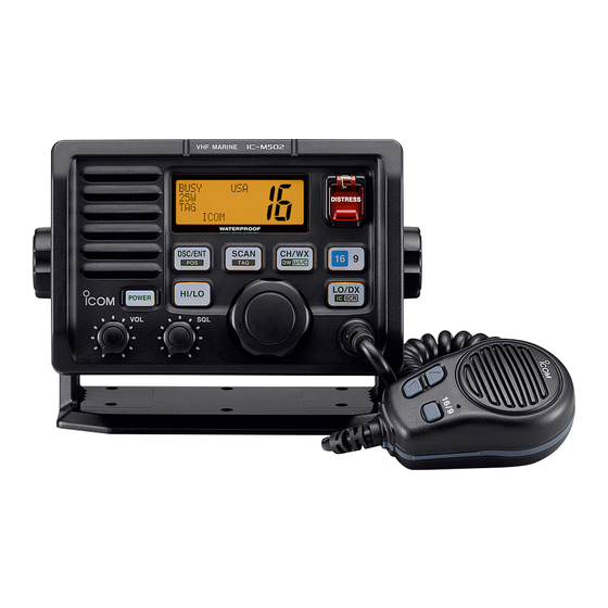
PANEL DESCRIPTION I Front panel Function Speaker display VHF MARINE WATERPROOF DSC/ENT HI/LO POWER q VOLUME CONTROL Adjusts the audio level. w POWER KEY Push to turn the transceiver power ON or OFF. iM502 e SQUELCH CONTROL DISTRESS Sets the squelch threshold level. r TRANSMIT POWER KEY ➥... - Page 9 y ATTENUATOR/INTERCOM/SCRAMBLER KEY LO/DX LO/DX SCR) SCR) ➥ Toggles the Attenuator function ON or OFF when pushed momentarily. (p. 8) • “ ” appears when the Attenuator is in use. The order of indication precedence is “ ,” “ ➥ Activates an optional Intercom function when pushed for 1 sec.
-
Page 10: I Function Display
PANEL DESCRIPTION I Function display q BUSY/TRANSMIT INDICATOR (p. 8) ➥ “ ” appears when receiving a signal or when the squelch opens. ➥ “ ” appears while transmitting. w POWER INDICATOR (p. 8) ➥ “ ” appears when high power is selected. ➥... -
Page 11: Panel Description........... 2
y DUPLEX INDICATOR (p. 7) Appears when a duplex channel is selected. • Duplex channel has a different TX and RX frequency. u CHANNEL NUMBER READOUT ➥ Indicates the selected operating channel number. “A” appears when a simplex channel is selected. “b” ap- pears when a receive only channel for a Canadian chan- nel group is selected. -
Page 12: Basic Operation
BASIC OPERATION I Channel selection D D Channel 16 Channel 16 is the distress and safety channel. It is used for establishing initial contact with another station and for emer- gency communications. Channel 16 is monitored during both Dualwatch and Tri-watch. While standing by, you must moni- tor Channel 16. - Page 13 D D U.S.A., Canadian and International channels There are 57 U.S.A., 61 Canadian and 57 International chan- nels. These channel groups may be specified for the operat- ing area. q Push to select a regular channel. CH/WX CH/WX U/I/C) U/I/C) •...
-
Page 14: I Receiving And Transmitting
BASIC OPERATION I Receiving and transmitting CAUTION: Transmitting without an antenna may dam- age the transceiver. q Push ] to turn power ON. POWER POWER w Set the audio and squelch levels. ➥ Rotate ] fully counterclockwise in advance. ➥ Rotate ] to adjust the audio output level. -
Page 15: I Call Channel Programming
I Call channel programming Call channel is used to select Channel 9 (default), however, you can program the call channel with your most often-used channels in each channel group for quick recall. q While pushing ] , push HI/LO CH/WX HI/LO CH/WX more times to select the desired channel group (U.S.A., In-... -
Page 16: Basic Operation ............ 6
BASIC OPERATION I Optional Voice scrambler operation D D Activating the Scrambler The optional Voice scrambler provides private communica- tions. In order to receive or send scrambled transmissions you must first activate the Scrambler function. To activate the function, an optional UT-98 or UT-112 is necessary. See p. 41 for setting the scrambler unit. -
Page 17: Dualwatch/Tri-Watch
I Description Dualwatch monitors Channel 16 while you are receiving an- other channel; Tri-watch monitors Channel 16 and call chan- nel while receiving another channel. DUALWATCH/TRI-WATCH SIMULATION Dualwatch Tri-watch • If a signal is received on Channel 16, Dualwatch/Tri-watch pauses on Channel 16 until the signal disappears. •... -
Page 18: Scan Operation
SCAN OPERATION I Scan types Scanning is an efficient way to locate signals quickly over a wide frequency range. The transceiver has Priority scan and Normal scan. When the Weather alert function is in use, the selected weather channel is checked while scanning. (p. 39) PRIORITY SCAN CH 01 CH 06... -
Page 19: I Setting Tag Channels
I Setting tag channels For more efficient scanning, add desired channels as tag channels or clear tag channels for unwanted channels. Chan- nels not tagged will be skipped during scanning. Tag chan- nels can be assigned to each channel group (U.S.A., Interna- tional, Canada) independently. -
Page 20: Dsc Operation
DSC OPERATION I MMSI code programming The 9-digit MMSI (Maritime Mobile Service Identity: DSC self ID) code can be programmed at power ON. This function is not available when the MMSI code has been programmed by the dealer. This code programming can be performed only twice. - Page 21 r Set the individual ID and ID name. • Edit the 9 digits of the appropriate distress ID by using - Push ] or ] to move the cursor forward or CH/WX SCAN CH/WX SCAN backward, respectively. 1st digit ‘0’ is fixed for a group ID. Thus an address ID input cannot start with ‘0.’...
-
Page 22: I Position And Time Programming
DSC OPERATION I Position and Time programming A distress call should include the ship’s position and time. If no GPS is connected, your position and UTC (Universal Time Coordinated) time should be input manually. They are in- cluded automatically when a GPS receiver (NMEA0183 ver. 2.0 or 3.01) is connected. -
Page 23: I Position/Time Indication
When no GPS receiver is connected, the transceiver displays the manually entered position and time. A GPS receiver appropriate for the IC-M502A is not supplied from Icom. A GPS receiver with NMEA0183 ver. 2.0 or 3.01 format is required for position indication. Ask your dealer about suitable GPS receivers. -
Page 24: I Distress Call
DSC OPERATION I Distress call A Distress call should be transmitted, if in the opinion of the Master, the ship or a person is in distress and requires imme- diate assistance. NEVER USE THE DISTRESS CALL WHEN YOUR SHIP IS NOT IN AN EMERGENCY. A DISTRESS CALL CAN BE USED ONLY WHEN IMMEDIATE HELP IS NEEDED. - Page 25 D D Normal call The nature of the Distress call should be included in the Dis- tress call. q Push ] to enter the DSC menu. DSC/ENT DSC/ENT w Rotate ] to select “ CHANNEL CHANNEL DSC/ENT DSC/ENT e Rotate ] to select the nature of the distress, CHANNEL CHANNEL...
- Page 26 DSC OPERATION y Push ] for 5 sec. to transmit the Distress call. DISTRESS DISTRESS u After transmitting the call, the transceiver waits for an ac- knowledgment call on Ch 70. • The Distress call is automatically transmitted every 3.5 to 4.5 minutes.
-
Page 27: I Transmitting Dsc Calls
I Transmitting DSC calls D D Transmitting Individual call The Individual call function allows you to transmit a DSC sig- nal to a specific ship only. q Push ] to enter the DSC menu. DSC/ENT DSC/ENT w Rotate ] to select “ CHANNEL CHANNEL DSC/ENT... - Page 28 DSC OPERATION y After transmitting the Individual call, standby on Channel 70 until an acknowledgement is received. u When the acknowledgement is received, the display changes to the previously selected channel with beeps. i Push and hold ] to communicate your message to the responding ship.
- Page 29 r Rotate ] to select an acknowledgement CHANNEL CHANNEL “ ” or “ ,” push DSC/ENT DSC/ENT t If you select “ ,” select the reason by rotating ] , push CHANNEL DSC/ENT CHANNEL DSC/ENT • ‘No reason given,’ ‘Congestion,’ ‘Busy,’ ‘Queue indication,’ ‘Sta- tion Barred,’...
- Page 30 DSC OPERATION D D Transmitting Group call The Group call function allows you to transmit a DSC signal to a specific group only. q Push ] to enter the DSC menu. DSC/ENT DSC/ENT w Rotate CHANNEL CHANNEL DSC/ENT DSC/ENT e Rotate ] to select the desired pre-pro- CHANNEL CHANNEL...
- Page 31 D D Transmitting All Ships call Large ships use Channel 70 as their ‘listening channel.’ When you want to announce a message to these ships, use the ‘All Ships Call’ function. q Push ] to enter the DSC menu. DSC/ENT DSC/ENT w Rotate ] to select “...
- Page 32 DSC OPERATION D D Transmitting Position Request call Transmit a Position Request call when you want to know a specific ship’s current position, etc. q Push ] to enter the DSC menu. DSC/ENT DSC/ENT w Rotate ] to select “ CHANNEL CHANNEL DSC/ENT...
- Page 33 D D Transmitting Position Report call Transmit a Position Report call when you want to announce your own position to a specific ship and to get answer, etc. q Push ] to enter the DSC menu. DSC/ENT DSC/ENT w Rotate ] to select “...
- Page 34 DSC OPERATION y Push ] to transmit the Position Report call. DSC/ENT DSC/ENT u After the Position Report call has been transmitted, the fol- lowing indication is displayed i Push any key to exit the condition and return to the normal operation.
-
Page 35: I Receiving Dsc Calls
I Receiving DSC calls D D Receiving a Distress call While monitoring Channel 70 and a Distress call is received: ➥ The emergency alarm sounds for 2 minutes. • Push any key to stop the alarm. ➥ “ ” appears in the display; then Channel 16 is automatically selected. - Page 36 DSC OPERATION D D Receiving an All Ships call While monitoring Channel 70 and an All Ships call is received: ➥ Emergency alarm sounds when the category is ‘Distress’ or ‘Urgency’; 3 beeps sound for other categories. ➥ “ ➥ Push ] to change to the channel specified by DSC/ENT DSC/ENT...
- Page 37 D D Receiving a Position Request call While monitoring Channel 70 and a Position Request call is received: ➥ “ ” appears in the display. ➥ Push ] to reply to the Position Request call; DSC/ENT DSC/ENT push other key to ignore the Position Request call. D D Receiving a Position Reply call While monitoring Channel 70 and a Position Reply call is re- ceived:...
-
Page 38: I Received Messages
DSC OPERATION I Received messages The transceiver automatically stores up to 20 distress mes- sages and 20 other messages. The messages can be used as an assistance to the logbook. q Push ] to select the DSC menu. DSC/ENT DSC/ENT w Rotate ] to select “... - Page 39 D D Other messages q Rotate select CHANNEL CHANNEL DSC/ENT DSC/ENT w Rotate ] to scroll to the desired message, CHANNEL CHANNEL push DSC/ENT DSC/ENT • When some messages are blinking, the messages have not been read. e Rotate “ ,”...
-
Page 40: I Dsc Set Mode
DSC OPERATION I DSC Set mode D D Add Address ID (See p.14 for detail) D D Delete Address ID (See p.15 for detail) D D Offset time This item sets the offset time from the UTC (Universal Time Coordinated) time. q Push ] to enter the DSC menu. - Page 41 D D MMSI code check The programmed 9-digit MMSI (DSC self ID) code can be checked in DSC Set mode. q Push ] to enter the DSC menu. DSC/ENT DSC/ENT w Rotate ] to select “ CHANNEL CHANNEL DSC/ENT DSC/ENT e Rotate ] to select “...
-
Page 42: Other Functions
• “ ” or “ ” appears on the caller or listener function dis- play, respectively. • To adjust the IC-M502A’s speaker output level, rotate • To adjust the HM-127’s speaker output level, push after pushing REMOTE-CONTROL MI- r After releasing the PTT switch you can hear the response... -
Page 43: I Microphone Lock Function
I Microphone lock function The Microphone lock function electrically locks the ] keys on the supplied microphone. This prevents 16/9 16/9 accidental channel changes and accidental function access. ➥ While pushing ] on supplied microphone, turn power 16/9 16/9 ON to toggle the Lock function ON or OFF. [Y]/[Z] I Display backlighting The function display and keys can be backlit for better visibil-... -
Page 44: Set Mode
SET MODE I Set mode programming Set mode is used to change the conditions of the trans- ceiver’s functions: scan mode (Normal or Priority), scan re- sume timer, weather alert, Dualwatch/Tri-watch selection, DSC watch, transceiver’s beep tone (transceiver or HM-127), internal speaker, LCD contrast (transceiver or HM-127), RF attenuation level, scrambler code, scrambler type and auto- matic acknowledgement. -
Page 45: I Set Mode Items
I Set mode items D D Scan mode The transceiver has 2 scan modes: Normal scan and Priority scan. Normal scan searches all tag channels in the selected channel group. Priority scan searches all tag channels in se- quence while monitoring Channel 16. Normal scan (default) D D Scan resume timer The scan resume timer can be selected as a pause (OFF) or... - Page 46 SET MODE D D DSC watch DSC watch monitors Channel 70 while you are receiving an- other channel. If a distress signal is received on Channel 70, the transceiver monitors Channel 16 and 70 alternately until the distress sig- nal disappears. If a signal is received on another channel, DSC watch pauses until the signal disappears.
- Page 47 D D Attenuation level This item sets the receive attenuation level for the Attenuator function from 3 levels. Attenuation level 1 (default) D D Scrambler code (Appears when a scrambler unit is installed) When an optional scrambler unit is installed, the scrambler code can be set depending on dealer setting.
-
Page 48: Connections And Maintenance
CONNECTIONS AND MAINTENANCE I Supplied accessories The following accessories are supplied: q Mounting bracket ... 1 w Microphone hanger ... 1 e Mic hanger screws (3 × 16) ... 2 r Mounting screws (5 × 20) ... 4 t Flat washers (M5) ... 4 y Spring washers (M5) ... -
Page 49: I Connections
I Connections q DC POWER CONNECTOR Connects the supplied DC power cable from this connector to an external 13.8 V DC power source. w EXTERNAL MICROPHONE JACKS Connects to optional HM-127 REMOTE-CONTROL MICRO- PHONE CAUTION: NEVER connect other microphones, such as the HM-134, as this may cause damage to the transceiver. -
Page 50: I Mounting The Transceiver
CONNECTIONS AND MAINTENANCE I Mounting the transceiver D D Using the supplied mounting bracket The universal mounting bracket supplied with your transceiver allows overhead or onboard mounting. • Mount the transceiver securely with the 4 supplied screws (M5 × 20) to a surface which is more than 10 mm thick and can support more than 5 kg. - Page 51 CONNECTIONS AND MAINTENANCE r Attach the clamps on either side of the IC-M502A. • Make sure that the clamps align parallel to the IC-M502A’s body. t Tighten the end bolts on the clamps (rotate clockwise) so that the clamps press firmly against the inside of the in- strument control panel.
-
Page 52: I Optional Unit Installation
CONNECTIONS AND MAINTENANCE I Optional unit installation CAUTION: DISCONNECT the DC power cable from the transceiver before performing any work on the transceiver. Otherwise, there is danger of electric shock and/or equip- ment damage. Follow the case opening procedure shown here when you want to install an optional unit. -
Page 53: I Dimensions
I Dimensions 145.0 (5 ⁄ 165.0 (6 ⁄ CONNECTIONS AND MAINTENANCE 31.4 ⁄ 53.0 ⁄ Unit: mm (inch) -
Page 54: Troubleshooting
TROUBLESHOOTING PROBLEM No power comes ON. • Bad connection to the power supply. No sound comes from • Squelch level is too high. the speaker. • Volume level is too low. • Speaker has been exposed to water. • Internal speaker is turned OFF. Sensitivity is low. -
Page 55: Channel List
Channel number Frequency (MHz) Channel number Frequency (MHz) CAN Transmit Receive 156.050 160.650 156.050 156.050 156.100 160.700 156.150 160.750 156.150 156.150 156.200 160.800 04A 156.200 156.200 156.250 160.850 05A 156.250 156.250 156.300 156.300 156.350 160.950 07A 156.350 156.350 156.400 156.400 156.450 156.450 156.500 156.500 156.550 156.550... -
Page 56: Specifications And Options
SPECIFICATIONS AND OPTIONS I Specifications D D General • Frequency coverage Transmit 156.025–157.425 MHz Receive 156.050–163.275 MHz • Mode : FM (16K0G3E) DSC (16K0G2B) • Channel spacing : 25 kHz • Current drain (at 13.8 V) : TX high Max. audio •... -
Page 57: I Options
SPECIFICATIONS AND OPTIONS I Options • MB-75 FLUSH MOUNT For mounting the transceiver to a panel. • SP-5 EXTERNAL SPEAKER A large, external speaker for superior audio output. • SP-10 EXTERNAL SPEAKER A compact, external speaker. Features easy installation. • UT-98/ UT-112 VOICE SCRAMBLER UNIT (pgs. 10, 41) Ensures private communications. -
Page 58: Hm-127 Remote-Control Microphone
HM-127 REMOTE-CONTROL MICROPHONE I Panel description The optional HM-127 remotely controls the IC-M502A and provides an optional Intercom function. D D Front and side keys q PTT SWITCH Push and hold to transmit; release to receive. w CHANNEL UP/DOWN KEYS ➥... - Page 59 • “LOCAL” appears when the Attenuator is in use. ➥ Activates the Intercom function when pushed for 1 sec. (pgs. 36, 63) ➥ Calls the IC-M502A when pushed and held while in In- tercom mode. (pgs. 36, 63) ➥ While pushing ] , activates an optional Voice scram- bler function.
-
Page 60: I Function Display
D D Top keys SCAN q POWER KEY [PWR] (pgs. 8, 57) Push for 2 sec. to turn the HM-127 power ON or OFF when the IC-M502A power is turned ON. w SCAN KEY SCAN SCAN ➥ Starts and stops Normal or Priority scan when tag chan- nels are programmed. - Page 61 e CHANNEL NUMBER READOUT ➥ Indicates the selected operating channel number. “A” appears when a simplex channel is selected. “b” ap- pears when a receive only channel for a Canadian chan- nel group is selected. (pgs. 6, 56) ➥ In Set mode, indicates the selected condition. (pgs. 38, r VOLUME INDICATOR (p.
-
Page 62: I Channel Selection
HM-127 REMOTE-CONTROL MICROPHONE I Channel selection D D Channel 16 q Push ] to select Channel 16. w Push ] to return to the CH/WX CH/WX condition before selecting Chan- nel 16, or push ] or ] to se- lect an operating channel. D D Call channel q Push for 1 sec. -
Page 63: I Receiving And Transmitting
I Receiving and transmitting q Push ] to turn power ON. w Push ] , then ] to adjust audio output level. • Push ] , then push ] to mute any audio noise, if nec- essary. e Push ] to select the desired channel. •... -
Page 64: I Lock Functions
HM-127 REMOTE-CONTROL MICROPHONE I Lock functions The Lock function electronically locks keys and switches to prevent accidental changes and function access from the mi- crophone. • All keys, switches and controllers on the transceiver are functional. D D Activating the Lock function ➥... -
Page 65: I Monitor Function
I Monitor function The monitor function releases the noise squelch mute of the microphone only. (An independent noise squelch system is employed.) ➥ Push for 1 sec. MONI Blinks when the Monitor to activate the Monitor func- function is in use. tion. -
Page 66: I Optional Voice Scrambler Operation
HM-127 REMOTE-CONTROL MICROPHONE I Optional Voice scrambler operation D D Activating the Scrambler q Select an operating channel, except for Channel 16, Chan- nel 70 or weather channels. w While pushing ] , push to turn the LO/DX] LO/DX SCR) SCR) Voice scrambler function ON. -
Page 67: I Starting A Scan
I Starting a scan q While pushing ] , push CH/WX CH/WX times to select the channel group (USA, INT, CAN), if de- sired. • When the Weather alert function is in use, select the desired weather channel with ] and CH/WX] CH/WX w Push... -
Page 68: I Set Mode Programming
HM-127 REMOTE-CONTROL MICROPHONE I Set mode programming Set mode is used to change the condition of the transceiver’s functions and the microphone’s own functions: Transceiver’s functions— scan mode (Normal or Priority), scan resume timer, weather alert, Dualwatch/Tri-watch, DSC watch, transceiver’s beep tone, internal speaker (transceiver), LCD contrast (trans- ceiver), RF attenuation level, scrambler code, scrambler type and automatic acknowledgement. -
Page 69: I Intercom Operation
I Intercom operation q Push LO/DX] for 1 sec. LO/DX SCR) SCR) to activate the Intercom function. • “IC” appears in the priority channel readout. • The channel comment disappears. w Push ] to talk. Appears when the inter- • “ ”... -
Page 70: I Hm-127 Supplied Accessories
HM-127 REMOTE-CONTROL MICROPHONE I HM-127 supplied accessories Accessories included with the HM-127: Qty. q Connection cable (OPC-1000: 6 m; 20 ft) ... 1 w Mounting base ... 1 e Microphone hanger ... 1 r Screws (M3 × 16; tapping) ... 5... -
Page 71: I Installation
I Installation The optional HM-127 can be connected to the transceiver di- rectly, as well as via the supplied connection cable for longer distance remote operation. The connector of the connection cable can be installed into a cabinet, wall, etc., as a built-in plug. - Page 72 HM-127 REMOTE-CONTROL MICROPHONE Mounting base 5 mm; ⁄ ˝ 2 mm; ⁄ ˝ Gasket...
-
Page 73: Template
165 mm (6 149 mm (5 MB-75 HM-127 24 to 27 (d) mm ⁄ to 1 ⁄ TEMPLATE ⁄ ⁄ 4–R11 2 mm; ⁄... - Page 74 A-6301H-1EX Printed in Japan 1-1-32 Kamiminami, Hirano-ku, Osaka 547-0003, Japan © 2003 Icom Inc.
Need help?
Do you have a question about the IC-M502A and is the answer not in the manual?
Questions and answers