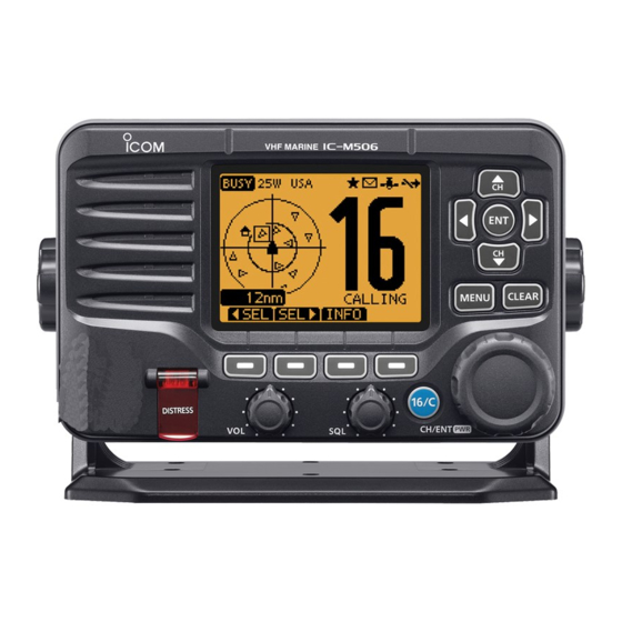
Icom ic-m506 Service Manual
Vhf marine transceiver
Hide thumbs
Also See for ic-m506:
- Instruction manual (124 pages) ,
- Service manual (45 pages) ,
- Specifications (4 pages)
Table of Contents
Advertisement
Advertisement
Table of Contents

Related Manuals for Icom ic-m506


Summary of Contents for Icom ic-m506
- Page 1 VHF MARINE TRANSCEIVER S-15102XZ-C1 September 2014...
- Page 2 Addresses are provided on the inside back cover for your convenience. Icom, Icom Inc. and the Icom logo are registered trademarks of Icom Incorporated (Japan) in Japan, the United States, the United Kingdom, Germany, France, Spain, Russia and/or other countries.
- Page 3 TABLE OF CONTENTS SECTION SPECIFICATIONS SECTION INSIDE VIEWS SECTION DISASSEMBLY INSTRUCTION SECTION CIRCUIT DESCRIPTION RECEIVER CIRCUITS ..................4-1 TRANSMITTER CIRCUITS ................4-2 FREQUENCY SYNTHESIZER CIRCUITS ............4-4 AIS RECEIVE CIRCUITS (AIS UNIT: UX-231) ..........4-4 NMEA2000 DATA ROUTING CIRCUITS (NMEA2000 UNIT: UC-232) ..... 4-4 VOLTAGE BLOCK DIAGRAM ................
-
Page 4: Specifications
SECTION 1. SPECIFICATIONS M IC-M506 General Transmitter • Frequency coverage: • Output power: 25 W/1 W Tx 156.025–157.425 MHz • Modulation system: Frequency modulation Rx 156.050–163.275 MHz • Max. frequency deviation: ±5.0 kHz CH70 156.525 MHz • Spurious emissions: Less than –70 dBc (high) •... - Page 5 M IC-M506EURO General Transmitter • Frequency coverage: • Output power: 25 W/1 W 156.000–162.000 MHz • Modulation system: Frequency modulation 156.000–163.425 MHz • Maximum frequency deviation: CH70 156.525 MHz ±5.0 kHz • Mode: FM, DSC • Spurious emissions: Less than 0.25 µW •...
-
Page 6: Inside Views
SECTION 2. INSIDE VIEWS • LOGIC UNIT 3.3 V REGULATOR ATIS DECODER (IC4) (IC13) RESET IC (IC11) DSC DECODER (IC12) TONE/BEEP BUFFER (IC2) (IC1) CPU CLOCK (X1) CLONE DATA LINE BUFFER PHOTO COUPLER (IC5) (IC9) CLONE DATA LINE BUFFER (IC7) EEPROM (IC14) BACKLIT DRIVER... - Page 7 • MAIN UNIT (TOP VIEW) 5 V REGULATOR (IC512) 5 V REGULATOR (Q501) AF POWER AMP (IC701) AF LINE SW (RL1) AF AMP AF LINE SW (IC881) (IC882) AF LINE SW AF LINE SW (IC505) (IC906) AF LINE SW (IC504) AF LINE SW (IC503) (IC506)
- Page 8 • MAIN UNIT (BOTTOM VIEW) MAIN POWER SUPPLY LINE SW (Q512) 3 V REGULATOR AF MUTE SW (IC511) (IC703) AF AMP (IC706) ELECTRONIC VOLUME (IC702) 8 V REGULATOR (IC102) 3 V REGULATOR (IC902) 1.5 V REGULATOR AF MUTE (IC903) (IC502) EEPROM EXPANDER (IC905)
- Page 9 SECTION 3. DISASSEMBLY INSTRUCTION 1. Removing the LOGIC UNIT 2. Removing the MAIN UNIT 1) Unscrew 14 screws from the rear panel, and 1) Remove IC CLIP. remove the front panel. 2) Disconnect the fl at cable. 2) Disconnect the fl at cables and speaker cable. FLAT CABLE FLAT...
-
Page 10: Circuit Description
SECTION 4. CIRCUIT DESCRIPTION 4-1 RECEIVE CIRCUITS RF CIRCUITS (MAIN UNIT) 1ST IF CIRCUITS FOR CH70 (MAIN UNIT) The RX signal from the antenna is passed through the LPF The RX signal from the RF circuits is applied to the 1st IF (L22, L23 and C104–C106), ANT SW (D15), and then ap- mixer (Q302), and mixed with the 134.825 MHz 1st LO signal, plied to the RF AMP (Q101). - Page 11 RX AF CIRCUITS (MAIN UNIT) • When the AF signal is output to the optional HM-195 The demodulated AF signal from the AF SW (IC882) is passed The RX AF signal from the AF SW (IC906, pin 2) is passed through the AF MUTE SW (IC505, pins 1, 2), de-emphasis through the AF MUTE SW (IC503, pins 2, 1) and amplifi...
- Page 12 TX AMP CIRCUITS (MAIN UNIT) 4-2 TRANSMIT CIRCUITS The TX signal is amplifi ed by the YGR (Q21) and power AMP TX AF CIRCUITS (MAIN UNIT) (IC1), and then passed through the TX output power detec- The AF signal from the microphone (MIC signal) is passed tor (D12 and D13), ANT SW (D14), and LPF (L22, L23 and through the MIC mute SW (IC502, pins 1, 2), and then ap- C104–C106), before being sent to the antenna.
- Page 13 4-4 AIS RECEIVER (AIS UNIT: UX-231) • VCOs The RX signal from the RF AMP (Q101) is applied to the AIS UNIT, through J5 on the MAIN UNIT of IC-M506. TX VCO The TX VCO (Q3, Q4 and D2–D4) generates both the TX The applied signal is passed through the SAW fi...
-
Page 14: Voltage Block Diagram
4-6 VOLTAGE BLOCK DIAGRAM Voltage from the power supply is routed throughout the transceiver, through regulators and switches. Transmit circuits CTRL IC512 Q13,Q15 Receive circuits CTRL IC511 IC902 3.3 V Noise canceller Receive circuits Q511 Q512 Option POWER AIS8V Option CTRL SUPPLY AIS8V... -
Page 15: Parts List
SECTION 5. PARTS LIST [MAIN UNIT] [MAIN UNIT] PARTS PARTS DESCRIPTION DESCRIPTION LOCATION LOCATION 1150002510 IC RA33H1516M1-325 D201 1750002780 S.DIO RN142GT2R [#01] T 114.8/58.2 1110006670 S.IC NJM2730F-TE1-#ZZZB 67.3/59.2 1750002780 S.DIO RN142GT2R [#10] IC19 1110007550 S.IC R2A20178NP 72.6/24.6 1750002780 S.DIO RN142GT2R [#11] IC101 1130016080 S.IC... - Page 16 [MAIN UNIT] [MAIN UNIT] PARTS PARTS DESCRIPTION DESCRIPTION LOCATION LOCATION 7030005090 S.RES ERJ2GEJ 104 X (100K) 80.8/43.0 R202 7030007290 S.RES ERJ2GEJ 222 X (2.2K) [#01] T 110.2/55.5 7030005050 S.RES ERJ2GEJ 103 X (10K) 84.2/47.5 7030007290 S.RES ERJ2GEJ 222 X (2.2K) [#10] 7030005050 S.RES ERJ2GEJ 103 X (10K) 78.6/34.4...
- Page 17 [MAIN UNIT] [MAIN UNIT] PARTS PARTS DESCRIPTION DESCRIPTION LOCATION LOCATION R571 7030005090 S.RES ERJ2GEJ 104 X (100K) 57.5/20.6 R901 7030005530 S.RES ERJ2GEJ 100 X (10) 65.5/31.5 R581 7030005530 S.RES ERJ2GEJ 100 X (10) 65.3/26.7 R902 7410001220 S.ARR EXB28V103JX 63.7/40.5 R582 7030005530 S.RES ERJ2GEJ 100 X (10) 65.3/27.6 R903...
- Page 18 [MAIN UNIT] [MAIN UNIT] PARTS PARTS DESCRIPTION DESCRIPTION LOCATION LOCATION C126 4030017630 S.CER C1005 CH 1H 120J-T 111.8/63.7 C286 4030016930 S.CER C1005 JB 1A 104K-T 106.7/9.5 C127 4030017570 S.CER C1005 CH 1H 040B-T 113.1/63.3 C287 4030017460 S.CER C1005 JB 1H 102K-T 113.4/13.3 C128 4030017570 S.CER C1005 CH 1H 040B-T...
- Page 19 [MAIN UNIT] [MAIN UNIT] PARTS PARTS DESCRIPTION DESCRIPTION LOCATION LOCATION C644 4030016790 S.CER C1005 JB 1E 103K-T 86.7/22.2 C714 4030017440 S.CER C1005 CH 1H 221J-T [#01] B 94.4/16.4 C649 4030017460 S.CER C1005 JB 1H 102K-T 85.4/22.5 4030017440 S.CER C1005 CH 1H 221J-T [#04] C650 4030018910 S.CER C1608 JB 0J 475K-T...
- Page 20 [MAIN UNIT] [LOGIC UNIT] PARTS PARTS DESCRIPTION DESCRIPTION LOCATION LOCATION C843 4030017460 S.CER C1005 JB 1H 102K-T 60.2/15.0 1140017111 S.IC STM32F101ZGT6(FX3570A1) C845 4030017460 S.CER C1005 JB 1H 102K-T 61.2/15.0 <TOMEN> 109.0/53.0 C847 4030017400 S.CER C1005 CH 1H 220J-T 62.2/15.0 1110006740 S.IC LMV358IPWR 84.7/45.3 C849...
- Page 21 [LOGIC UNIT] [LOGIC UNIT] PARTS PARTS DESCRIPTION DESCRIPTION LOCATION LOCATION 7030012320 S.RES ERJ2RKD 2203X (220K) 92.6/48.8 R167 7030005090 S.RES ERJ2GEJ 104 X (100K) [#06] B 56.1/50.3 7030004980 S.RES ERJ2GEJ 101 X (100) 106.6/38.2 7030005090 S.RES ERJ2GEJ 104 X (100K) [#07] 7030010040 S.RES ERJ2GEJ-JPW 101.7/37.8 7030005090 S.RES ERJ2GEJ 104 X (100K)
- Page 22 [LOGIC UNIT] [DIAL UNIT] PARTS PARTS DESCRIPTION DESCRIPTION LOCATION LOCATION C174 4030016790 S.CER C1005 JB 1E 103K-T [#06] B 51.7/61.2 6510030480 CON IMSA-9210B-1-04ZA311-PT1 4030016790 S.CER C1005 JB 1E 103K-T [#07] 4030016790 S.CER C1005 JB 1E 103K-T [#16] 4030016790 S.CER C1005 JB 1E 103K-T [#17] 2250000730 ENC TP90N245AE20PY-14.5F-3338...
- Page 23 [VOL UNIT] [SQL UNIT] PARTS PARTS DESCRIPTION DESCRIPTION LOCATION LOCATION 7210003431 VAR F09117N-8 B10K L15KQ-1 7210003431 VAR F09117N-8 B10K L15KQ-1 <SLVJ> <SLVJ> 6510030470 CON IMSA-9210B-1-03ZA311-PT1 6510030470 CON IMSA-9210B-1-03ZA311-PT1 Eqv.= This component is equivalent to the REF No. component listed above, and M.=Mounted side (T: Mounted on the Top side, B: Mounted on the Bottom side) may be substituted on parts orders and repairs.
- Page 24 DESCRIPTION LOCATION PARTS DESCRIPTION 4030016790 S.CER C1005 JB 1E 103K-T 7.8/13.5 LOCATION 1140017121 S.IC STM32F103RCT6(EX3572A1) <TOMEN> 22.5/33.5 6510030290 CON ICOM-CCBPM08MCC <ODS> 1110007780 S.IC NJU7704F3-28A-TE1-#ZZZH 24.5/12.2 6510025142 S.CON 10FLT-SM2-TB(LF)(SN)(M) 8.5/18.3 1130016110 S.IC TC7WH14FK(TE85LF) *0 11.5/12.2 6910019100 S.BEA MPZ1608S101AT 6.3/13.1 1510001090 S.TRA KTA2015Y-RTK/P 24.5/8.2...
- Page 25 24.2/15.9 6050013730 S.XTA CR-968 DSX321G 38.35 MHz 34.8/15.4 6070000310 S.DIS JTBM450CX70 <JJE> 32.0/4.6 6050013960 S.XTA CR-869A DSA321SCH 19.2 MHz 4.9/24.5 6510030360 CON ICOM-MMAPM05MCC <ODS> 6510022692 S.CON 06FLT-SM2-TB(LF)(SN)(M) 26.5/19.7 6200009930 S.COI C2012C-68NG-A 37.2/48.1 6200011220 S.COI C2012C-R47J-A 30.8/34.8 6910018270 S.BEA MMZ1608Y301CT 10.3/23.5 6200002651 S.COI...
- Page 26 [MAIN UNIT] PARTS DESCRIPTION LOCATION 7030005310 S.RES ERJ2GEJ 124 X (120K) 17.7/28.7 7030005310 S.RES ERJ2GEJ 124 X (120K) 16.7/28.7 7030005090 S.RES ERJ2GEJ 104 X (100K) 16.0/6.8 7030005090 S.RES ERJ2GEJ 104 X (100K) 15.0/6.8 7030007280 S.RES ERJ2GEJ 331 X (330) 13.1/43.8 4030017390 S.CER C1005 CH 1H 180J-T 34.7/48.1 4030016790 S.CER C1005 JB 1E 103K-T...
- Page 27 SECTION 6. MECHANICAL PARTS [CHASSIS PARTS] [CHASSIS PARTS] ORDER ORDER DESCRIPTION QTY. DESCRIPTION QTY. 6510004881 MR-DSE-01-1 <GA> MP16 8930088980 3570 R-PACKING (TOP) MP21 8810010610 PHB0 M3 X 8 SUS S (BT) 8920000790 CAB-1091 MP22 8810008661 PHBT M3 X 8 NI-ZC3 8920000800 CAB-1092 MP23 8810010021 PH BT M2.6X 8 NI-ZC3...
- Page 28 [#41] ORDER DESCRIPTION QTY. 8930089610 3570 MIC CAP [#44] 8930089610 3570 MIC CAP [#45] 6510030290 ICOM-CCBPM08MCC <ODS> 8930089610 3570 MIC CAP [#46] 6510025142 10FLT-SM2-TB (LF) (SN) (M) 8930089610 3570 MIC CAP [#47] 8930089610 3570 MIC CAP [#49] 8930089610 3570 MIC CAP...
- Page 29 [#47] DESCRIPTION QTY. 8900010280 OPC-1000 [#49] 8900010280 OPC-1000 [#50] 6510030360 ICOM-MMAPM05MCC <ODS> 6510022692 06FLT-SM2-TB (LF) (SN) (M) 8950006870 2917 MIC HANGER 8010022970 3570 MOBILE BRACKET 8820001460 3054 KNOB BOLT [ACCESSORIES] 8810004700 PHA M3 X16 SUS 8810001490 PHA M5 X20 SUS...
- Page 30 LOGIC UNIT DS1(LOGIC) (5030003860) MP21(FRONT)×9 (8810010610) MP22(FRONT)×3 (8810008661) MP4(FRONT) (8930089030) MP10(FRONT) MP16(FRONT) (8930051970) (8930055841) SP1(FRONT) (2510001800) MP6(FRONT) (8930088990) MP7(FRONT) (8930089100) MP9(FRONT) (8930088970) MP5(FRONT) (8310084000) MP8(FRONT) (8930088960) MP11(FRONT) VOL UNIT MP25(FRONT)×7 W2(CHASSIS) (Refer to the list.) R1(VOL) (8810010620) (8920000800) (7210003431) MC1(FRONT) SQL UNIT (Refer to the list.) R1(VOL)
- Page 31 SECTION 7 BOARD LAYOUTS • LOGIC UNIT B-8132 (TOP VIEW) DS10...
- Page 32 • LOGIC UNIT B-8032 (BOTTOM VIEW) IC11 B8132 R102 C112 R107 R108 IC17 R167 R164 C179 C106 R116 C162 R118 C103 R120 C105 C104 C166 C165...
- Page 33 • DIAL UNIT B-8133 (TOP VIEW) • MAIN UNIT B-8131 (TOP VIEW) C105 D503 D504 C516 C517 R111 C127 C111 D601 C131 C122 L111 R101 Q101 C138 FI201 C132 C113 C116 C118 C202 C512 C506 L201 C144 C514 C504 R202 C511 •...
- Page 34 • DIAL UNIT B-8133 (BOTTOM VIEW) • MAIN UNIT B-8131 (BOTTOM VIEW) B8133 C128 C311 R113 R112 C129 L113 R913 C321 R312 R912 Q302 C622 R361 C623 R229 • VOL/SQL UNIT B-8134 C332 C624 R505 C333 C931 R925 R504 C936 C510 R503 L311...
- Page 35 • NMEA2000 UNIT (UX-232) MAIN UNIT B-8033A • AIS UNIT (UX-231) CONNECT UNIT B-7971B AISRXDI NM2KTXD GPSRXD NM2KRXD NM1RXD NM2KRST ICF3 NM2KOPTI CAN_RX CAN_TX MISO SCLK MOSI • NMEA2000 UNIT (UX-232) CONNECT UNIT B-8034A...
- Page 36 SECTION 8 GENERAL WIRING KEYM LOGIC UNIT SMART MIC MIC-G MIC-IN HM-205B KEYM KEYM MIC-G MIC-G MIC-IN MIC-IN VLCD VB1+ VB1- VBO- VB0+ (9035700010) DIAL UNIT FRONT UNIT DIALA DIALA DIALB DIALB PWSW RESETB VOL UNIT VOLV VOLV SQL UNIT SQLV SQLV EVDATA...
-
Page 37: Block Diagram
SECTION 9 BLOCK DIAGRAM LOGIC UNIT FRONT UNIT HM-205B HM-205RB KEYM KEYM KEYM KEYM INT SP DIAL UNIT DIALA DIALB TP90N1007AE20 IC702A: IC701A: IC704: IC706: M61545AFP LA4628 TC7S66FU LMV321IDCK VOL UNIT EVOL MUTE VOLV 1VOL3P SQL UNIT SQLV 1VOL3P ATIS DECODER Q1:2SB1201 (#06,#07) - Page 38 JTBM450CX70 FI204:LTWC450E1 X201 CERAMIC HL/ATT WXDEC IC201:NJM2591V (ATISDEC) D201:RN142G FI202:FL-472 (USA, AUS) MAIN UNIT IC514D:LMV324IPW FI203:FL-472 D202: NOISEV HSMS2829 MAINDET 2ND IF XTAL MRSSI IC514A:LMV324IPW RSSI Q205:KTC4080 30.15MHz Q202,Q203: FI201: PMBFJ310x2 HDF160F IC505C: TC74VHC4066AFK NOISE NOIZV NOISE 2ND LO MIC-IN DSCDEC BUFF 29.700MHz...
- Page 39 • NMEA2000 UNIT (UX-232) LOGIC UNIT (IC-M506) MAIN UNIT CONNECT UNIT IC2:NJU7704 RESET CTRL IC1:TA78M05F D1:RR264M Q1:KTA2015 Q2:LDTC144EE CI-V CAN TX PHOTO COUPLE BUFF BUFF Q3:L2SA1576 IC3:TC7WH14FK IC6: IC5: Q4:L2SC4081 SN74AHCT1G04 PC410L0NIP0F IC1:STM32F103RCT6 D1:L1SS400 NM2K DATA LEVEL CONV PHOTO CAN RX...
- Page 40 SECTION 10 VOLTAGE DIAGRAM • LOGIC UNIT CP31 5 . 0 V T x : 0 . 0 V 1 1 . 9 V R x : 5 . 7 V BOOT AISRXD toNMEA2K 1 2 . 0 V AISRXDI NM2KTXD EVDATAO BEEPO...
- Page 41 • MAIN UNIT (1/2) Tx: 5.0 V Rx: 0.0 V Tx: 1.5 V KTA2015 Rx: 0.0 V JDP2S12CR C103 0.68U 0.001 35.0N 35.0N To ANT 41.0N Tx: 0.0 V RN142G Rx: 7.3 V 1.5P 2SC4226 LDTC144EE R101 LDTC144EE 2SC5065 KTC4080 C113 Tx: 0.0 V Rx: 1.2 V...
- Page 42 • MAIN UNIT (2/2) R914 NCSCK IC906 2SB1143 I/O1 C535 R551 C537 C538 R564 R563 Q501 O/I1 CONT1 R526 O/I2 CONT4 0.22 0.022 0.0047 R911 CP26 I/O2 I/O4 VBIAS CONT2 O/I4 R562 CONT3 O/I3 NCSDATA I/O3 1.2k TC74VHC4066AFK KTC811U C914 C539 R560 C532...
- Page 43 • NMEA2000 UNIT (UX-232) • AIS UNIT (UX-231) MAIN UNIT MAIN UNIT CAN_TX JTBM450CX70 AIS8V CAN_RX 3.5V 3.9k NJM2591V 0.033 C2012C AIS 2, CH B, CH88B, 162.025 MHz 100K CP18 AIS8V 180k 180k 0.01 IF 38.850 MHz 3.3k 0.0022 0.033 0.01 CF20OPEN 0.0022...
- Page 44 Highway 17A Delta, B.C., V4K 5B8, Canada : http://www.icomspain.com Phone : +1 (604) 952-4266 Fax : +1 (604) 952-0090 E-mail : icom@icomspain.com : http://www.icomcanada.com E-mail : info@icomcanada.com Blacksole House, Altira Park, Herne Bay, Kent CT6 6GZ, UK Phone : +44 (0) 1227 741741...
- Page 45 S-15102XZ-C1 1-1-32, Kamiminami, Hirano-ku, Osaka 547-0003, Japan © 2014 Icom Inc.
Need help?
Do you have a question about the ic-m506 and is the answer not in the manual?
Questions and answers