Icom IC-M502 Instruction Manual
Icom ic-m502 radio-marine: instruction manual
Hide thumbs
Also See for IC-M502:
- Instruction manual (62 pages) ,
- Service manual (44 pages) ,
- Operational manual (42 pages)
Table of Contents
Advertisement
Quick Links
INSTRUCTION MANUAL
VHF MARINE TRANSCEIVER
iM502
This device complies with Part 15 of the FCC rules. Operation is sub-
ject to the following two conditions: (1) This device may not cause
harmful interference, and (2) this device must accept any interference
received, including interference that may cause undesired operation.
Advertisement
Table of Contents

Subscribe to Our Youtube Channel
Related Manuals for Icom IC-M502


Summary of Contents for Icom IC-M502
- Page 1 INSTRUCTION MANUAL VHF MARINE TRANSCEIVER iM502 This device complies with Part 15 of the FCC rules. Operation is sub- ject to the following two conditions: (1) This device may not cause harmful interference, and (2) this device must accept any interference received, including interference that may cause undesired operation.
-
Page 2: Important
6. Any other information which might facilitate the rescue. SAVE THIS INSTRUCTION MANUAL — carefully and completely struction manual contains important operating instructions for the IC-M502. Or, transmit your distress call using digital selective calling on channel 70. USING DIGITAL SELECTIVE CALLING DISTRESS CALL PROCEDURE 1. -
Page 3: Table Of Contents
TABLE OF CONTENTS IMPORTANT ... i IN CASE OF EMERGENCY ... i TABLE OF CONTENTS ... ii CAUTIONS ... iii 1 OPERATING RULES ... 1 2 PANEL DESCRIPTION ... 2 – 5 Panel description ... 2 Function display ... 4 Microphone ... -
Page 4: Cautions
This may pose a fire hazard or result in an electric shock. CAUTION: Changes or modifications to this device, not ex- pressly approved by Icom Inc., could void your authority to operate this device under FCC regulations. NEVER connect the transceiver to a power source of more than 16 V DC or use reverse polarity. -
Page 5: Operating Rules
PRIORITIES • Read all rules and regulations pertaining to priorities and keep an up-to-date copy handy. Safety and distress calls take priority over all others. • You must monitor channel 16 when you are not operating on another channel. • False or fraudulent distress signals are prohibited and pun- ishable by law. -
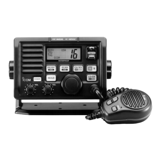
Page 6: Panel Description
PANEL DESCRIPTION Panel description Function display Speaker q POWER SWITCH [POWER] Push to toggle the transceiver power ON and OFF. w VOLUME CONTROL [VOL] Adjusts the audio level. (p. 8) e SQUELCH CONTROL [SQL] Sets the squelch threshold level. (p. 8) iM502 VHF MARINE DISTRESS... - Page 7 While pushing [HI/LO], rotate [CHANNEL] to adjust the brightness of the LCD and switch backlight. y ATTENUATOR/INTERCOM/SCRAMBLER SWITCH [LO/DX•IC•SCR] Toggles the attenuator function ON and OFF when pushed momentarily. (p. 8) • “LOCAL” appears when the attenuator is in use. The order of indication precedence is “LOCAL,”...
-
Page 8: Function Display
PANEL DESCRIPTION Function display BUSY CALL CALLING q BUSY/TRANSMIT INDICATOR (p. 8) “BUSY” appears when receiving a signal or when the squelch opens. “TX” appears while transmitting. w POWER INDICATOR (p. 8) “25W” appears when high power is selected. “1W” appears when low power is selected. e TAG CHANNEL INDICATOR (p. -
Page 9: Panel Description .......... 2
Microphone q PTT SWITCH [PTT] Push and hold to transmit; release to receive. (p. 8) w CHANNEL UP/DOWN SWITCHES [Y Y ]/[Z Z ] Push either switch to change the operating memory chan- nel, set mode contents, etc. (p. 8) e TRANSMIT POWER SWITCH [HI/LO] Same as the [HI/LO] switch on the front panel. -
Page 10: Basic Operation
BASIC OPERATION Channel selection Channel 16 Channel 16 is the distress and safety channel. It is used for establishing initial contact with another station and for emer- gency communications. Channel 16 is monitored during both dualwatch and tri-watch. While standing by, you must monitor channel 16. -
Page 11: Microphone Lock Function
U.S.A. channels CH/WX Push HI/LO U/I/C CANADA Canadian channels International channels Weather channels There are 10 weather channels. Used for monitoring weather channels from the NOAA (National Oceanographic and At- mospheric Administration) broadcasts. The transceiver can detect a weather alert tone on the se- lected weather channel while receiving the channel, during standby on a regular channel or while scanning. -
Page 12: Receiving And Transmitting
BASIC OPERATION Receiving and transmitting CAUTION: Transmitting without an antenna may dam- age the transceiver. q Push [POWER] to turn power ON. w Set the audio and squelch levels. Rotate [SQL] fully counterclockwise in advance. Rotate [VOL] to adjust the audio output level. Rotate [SQL] clockwise until the noise disappears. -
Page 13: Call Channel Programming
Call channel programming The call channel is used to select channel 9, however, you can program your most often-used channels in each channel group for quick recall. q While pushing [HI/LO], push [CH/WX•DW•U/I/C] one or more times to select the desired channel group (U.S.A., In- ternational, Canada) to be programmed. -
Page 14: Basic Operation ............ 6
BASIC OPERATION Optional voice scrambler operation Activating the scrambler The optional voice scrambler provides private communica- tions. In order to receive or send scrambled transmissions you must first activate the scrambler function. To activate the function, an optional UT-98 or UT-112 is necessary. See p. 33 for selecting the unit. -
Page 15: Dualwatch/Tri-Watch
Description Dualwatch monitors channel 16 while you are receiving an- other channel; tri-watch monitors channel 16 and the call channel while receiving another channel. DUALWATCH/TRI-WATCH SIMULATION Dualwatch Tri-watch • If a signal is received on channel 16, dualwatch/tri-watch pauses on channel 16 until the signal disappears. •... -
Page 16: Scan Operations
SCAN OPERATIONS Scan types Scanning is an efficient way to locate signals quickly over a wide frequency range. The transceiver has priority scan and normal scan. When the weather alert function is in use, the selected weather channel is checked while scanning. (p. 31) PRIORITY SCAN CH 01 CH 06... -
Page 17: Setting Tag Channels
Setting tag channels For more efficient scanning, add desired channels as tag channels or clear tag channels for unwanted channels. Chan- nels set as non-tag channels will be skipped during scanning. Tag channels can be assigned to each channel group (U.S.A., International, Canada) independently. -
Page 18: Dsc Operation
DSC OPERATION MMSI code programming The 9-digit MMSI (DSC self ID) code can be programmed at power ON. This function is not available when the MMSI code has been programmed by the dealer. This code programming can be performed only 2 times. q Turn power OFF. -
Page 19: Position Indication
When no GPS receiver is connected, the transceiver displays the manually entered position and time. A GPS receiver appropriate for the IC-M502 is not supplied from Icom. An NMEA0183 ver. 2.0 is required for position in- dication. Ask your dealer about the GPS receiver. -
Page 20: Distress Call
DSC OPERATION Distress call A distress call should be transmitted if, in the opinion of the Master, the ship or a person is in distress and requires imme- diate assistance. NEVER USE THE DISTRESS CALL WHEN YOUR SHIP IS NOT IN AN EMERGENCY. A DISTRESS CALL CAN BE USED ONLY WHEN IMMEDIATE HELP IS NEEDED. -
Page 21: Transmitting Dsc Calls
• The ID code for the individual call can be set in advance. (p. 22) Sel address ˘Manual set Icom John DSC OPERATION t Push [DSC/ENT] to transmit the individual call. • Channel 70 is selected and the individual call is transmitted to the selected station. - Page 22 ˘INDV ACK All ships r Rotate the channel selector to select the desired individ- ual address or ID code, then push [DSC/ENT]. Sel address ˘Icom John t Rotate the channel selector to select an acknowledgement (‘Able’ or ‘Unable’), then push [DSC/ENT]. Comply ˘Able Unable...
- Page 23 Transmitting all ships call Large ships use channel 70 as their “listening channel.” When you want to announce a message to these ships, use the “all ships call” function. q Select a desired channel other than channel 70. w Push [DSC/ENT] to select the DSC menu. e Rotate the channel selector to select “All ships”...
- Page 24 Transmit a position reply call when a position request call is received. q When a position request call is received, the function dis- play shows as follows. Received POS request < Icom Ans[DSC/ENT] w Push [DSC/ENT] to reply the position request call; push [HI/LO] to ignore the position request call.
-
Page 25: Setting The Distress Information
Setting the distress information The nature of the distress call should be included in the dis- tress call. q Push [DSC/ENT] to select the DSC menu. w Rotate the channel selector to select “DTRS set” and push [DSC/ENT]. Sel item RCV calls ˘DTRS set Set-up e Rotate the channel selector to select the nature of the dis-... -
Page 26: Dsc Individual Id
DSC OPERATION DSC individual ID A total of 40 DSC address ID’s can be programmed and named with up to 10 characters. Programming address ID q Push [DSC/ENT] to select the DSC menu. w Rotate the channel selector to select “Set-up” and push [DSC/ENT]. -
Page 27: Receiving Dsc Calls
r Select the desired ID name with the channel selector, then push [DSC/ENT]. Delete ID ˘Icom2 John Smith t Push [DSC/ENT] to delete the address ID; push other switch to exit the condition. DSC OPERATION Receiving DSC calls Receiving a distress call While monitoring channel 70 and a distress call is received: Emergency alarm sounds for 2 minutes. - Page 28 DSC OPERATION Receiving a distress relay acknowledgement While monitoring channel 70 and a distress relay acknowl- edgement is received: Emergency alarm sounds for 2 minutes. • Push any switch to stop the alarm. “Received DTRS RLY ACK” appears in the display; then, channel 16 is automatically selected.
- Page 29 Received Individual Routine < Icom3 Receiving a geographical area call While monitoring channel 70 and a geographical area call (for the area you are in) is received: Emergency alarm or beeps sound depending on the re- ceived category. “Geographic Distress,” “Geographic Safety,” “Geographic Urgency”...
-
Page 30: Dsc Set Mode
DSC OPERATION DSC set mode Offset time This item sets the offset time from the UTC (Universal Time Coordinated) time. q Push [DSC/ENT] to select the DSC menu. w Rotate the channel selector to select “Set-up” and push [DSC/ENT]. Sel item RCV calls DTRS set ˘Set-up... - Page 31 MMSI code check The 9-digit MMSI (DSC self ID) code can be checked in set mode. q Push [DSC/ENT] to select the DSC menu. w Rotate the channel selector to select “Set-up” and push [DSC/ENT]. Sel item RCV calls DTRS set ˘Set-up e Rotate the channel selector to select ‘MMSI check,’ then push [DSC/ENT].
-
Page 32: Receive Messages
DSC OPERATION Receive messages The transceiver automatically stores up to 20 distress mes- sages and 20 other messages. The messages can be used as an assistance to the logbook. q Push [DSC/ENT] to select the DSC menu. w Rotate the channel selector to select “RCV calls” and push [DSC/ENT]. -
Page 33: Intercom Operation
• “TALK” or “LSTN” appears on the caller or listener function dis- play, respectively. • To adjust the IC-M502’s speaker output level, rotate [VOL]. INTERCOM OPERATION • To adjust the HM-127’s speaker output level, push [Y]/[Z] after pushing [VOL]. -
Page 34: Set Mode
SET MODE Set mode programming Set mode is used to change the conditions of the trans- ceiver’s functions: scan mode (normal or priority), scan re- sume timer, weather alert, dualwatch/tri-watch selection, DSC watch, transceiver’s beep tone, internal speaker (transceiver or HM-127), LCD contrast (transceiver or HM-127), RF atten- uation level, scrambler code and scrambler type. -
Page 35: Set Mode Items
Set mode items Scan mode The transceiver has 2 scan modes: normal scan and priority scan. Normal scan searches all tag channels in the selected channel group. Priority scan searches all tag channels in se- quence while monitoring channel 16. Set mode Scan mode Normal scan (default) - Page 36 SET MODE DSC watch DSC watch monitors channel 70 while you are receiving an- other channel. If a distress signal is received on channel 70, the transceiver monitors channel 16 and 70 alternately until the distress sig- nal disappears. If a signal is received on another channel, DSC watch pauses until the signal disappears.
- Page 37 LCD contrast This item adjusts the contrast of the LCD in 8 steps. Set mode contrast LCD contrast 4 (default) The optional HM-127 has it’s own setting for the beep tone. Attenuation level This item sets the receive attenuation level for the attenuator function from 3 levels.
-
Page 38: Connections And Maintenance
CONNECTIONS AND MAINTENANCE Supplied accessories The following accessories are supplied: q Mounting bracket ... 1 w Microphone hanger (OPC-562) ... 1 e Mic hanger screws (3 16) ... 2 r Mounting screws (5 20) ... 2 t Flat washers (M5) ... 2 y Spring washers (M5) ... -
Page 39: Connections
Connects to an optional GPS receiver to input the position data and time data. • A GPS receiver appropriate for the IC-M502 is not supplied from Icom. An NMEA0183 ver. 2.0 is required for position or time indi- cation, etc. Ask your dealer about the GPS receiver. -
Page 40: Mounting The Transceiver
CONNECTIONS AND MAINTENANCE Mounting the transceiver Using the supplied mounting bracket The universal mounting bracket supplied with your transceiver allows overhead or dashboard mounting. • Mount the transceiver securely with the 2 supplied screws 20) to a surface which is more than 10 mm thick and can support more than 5 kg. - Page 41 CONNECTIONS AND MAINTENANCE r Attach the clamps on either side of the IC-M502. • Make sure that the clamps align parallel to the IC-M502’s body. t Tighten the end bolts on the clamps (rotate clockwise) so that the clamps press firmly against the inside of the in- strument control panel.
-
Page 42: Optional Unit Installation
CONNECTIONS AND MAINTENANCE Optional unit installation CAUTION: DISCONNECT the DC power cable from the transceiver before performing any work on the transceiver. Otherwise, there is danger of electric shock and/or equip- ment damage. Follow the case opening procedure shown here when you want to install an optional unit, etc. -
Page 43: Dimensions
CONNECTIONS AND MAINTENANCE Dimensions 145.0 (5 ⁄ ˝) 31.4 53.0 165.0 (6 ⁄ ˝) ⁄ ˝) ⁄ ˝) Unit: mm (inch) -
Page 44: Troubleshooting
TROUBLESHOOTING PROBLEM No power comes ON. • Bad connection to the power supply. No sound comes from • Squelch level is too deep. the speaker. • Volume level is too low. • Speaker has been exposed to water. • Internal speaker is turned OFF. Sensitivity is low. -
Page 45: Channel List
Channel number Frequency (MHz) Channel number Frequency (MHz) CAN Transmit Receive 156.050 160.650 156.050 156.050 156.100 160.700 156.150 160.750 156.150 156.150 156.200 160.800 04A 156.200 156.200 156.250 160.850 05A 156.250 156.250 156.300 156.300 156.350 160.950 07A 156.350 156.350 156.400 156.400 156.450 156.450 156.500 156.500 156.550 156.550... -
Page 46: Specifications And Options
SPECIFICATIONS AND OPTIONS Specifications General • Frequency coverage Transmit 156.025–157.425 MHz Receive 156.050–163.275 MHz • Mode : FM (16K0G3E) DSC (16K0G2B) • Channel spacing : 25 kHz • Current drain (at 13.8 V) : TX high Max. audio • Power supply requirement: 13.8 V DC ±15% •... -
Page 47: Options
SPECIFICATION AND OPTIONS Options • MB-75 FLUSH MOUNT For mounting the transceiver to a panel. • SP-5 EXTERNAL SPEAKER A large, external speaker for superior audio output. • SP-10 EXTERNAL SPEAKER A compact, external speaker. Features easy installation. • UT-98 VOICE SCRAMBLER UNIT (pgs. 10, 33) •... -
Page 48: Hm-127 Remote-Control Microphone
HM-127 REMOTE-CONTROL MICROPHONE Panel description The optional HM-127 remotely controls the IC-M502 and pro- vides an optional intercom function. q POWER SWITCH [PWR] (pgs. 8, 51) Push for 2 sec. to turn the HM-127 power ON or OFF when the IC-M502 power is turned ON. - Page 49 • “LOCAL” appears when the attenuator is in use. Activates the intercom function when pushed for 1 sec. (pgs. 29, 56) Calls the IC-M502 when pushed and held while in inter- com mode. (pgs. 29, 56) While pushing [H/L], activates an optional voice scram- bler function.
-
Page 50: Function Display
HM-127 REMOTE-CONTROL MICROPHONE Function display !8 !7 TX BUSY q CHANNEL GROUP INDICATOR (pgs. 6, 50) Indicates whether an International (INT), U.S.A. (USA) or Canadian (CAN) channel is selected. w KEY LOCK INDICATOR (p. 52) Appears while the key lock function is in use. Flashes while the all key lock function is in use. -
Page 51: Hm-127 Supplied Accessories
!1 DUAL/TRI WATCH INDICATOR (pgs. 11, 54) “DUAL” appears during dualwatch; “TRI” during tri-watch. !2 WEATHER CHANNEL INDICATOR (pgs. 7, 50) “WX” appears when a weather channel is selected. “ALT” appears when the weather alert function is in use; flashes when an alert tone is received. !3 LOW POWER INDICATOR (pgs. -
Page 52: Installation
HM-127 REMOTE-CONTROL MICROPHONE Installation The optional HM-127 can be connected to the transceiver di- rectly, as well as via the supplied connection cable for longer distance remote operation. The connector of the connection cable can be installed into a cabinet, wall, etc., as a built-in plug. - Page 53 HM-127 REMOTE-CONTROL MICROPHONE Mounting base 5 mm; ⁄ ˝ 2 mm; ⁄ ˝ Gasket...
-
Page 54: Channel Selection
HM-127 REMOTE-CONTROL MICROPHONE Channel selection Channel 16 q Push [16] to select channel 16. w Push [CH/WX] to return to the condition before selecting chan- nel 16, or push [Y] or [Z] to se- lect operating channel. Call channel q Push [16•9] for 1 sec. to select call channel. -
Page 55: Receiving And Transmitting
Receiving and transmitting q Push [PWR] to turn power ON. w Push [VOL], then [Y]/[Z] to adjust audio output level. • Push [SQL], then [Y]/[Z] to mute any audio nose, if necessary. e Push [Y]/[Z] to select the desired channel. •... -
Page 56: Lock Functions
HM-127 REMOTE-CONTROL MICROPHONE Lock functions The lock function electronically locks keys and switches to prevent accidental changes and function access from the mi- crophone. • All keys, switches and controllers on the transceiver are functional. Activating the lock function Push [SQL] while pushing [H/L] to turn the lock function ON and OFF. -
Page 57: Call Channel Programming
Call channel programming q Push [CH/WX•U/I/C] several times while pushing [H/L] to select the desired channel group (USA, INT, CAN) to be programmed. w Push [16•9] for 1 sec. to select the call channel of the selected chan- nel group. •... -
Page 58: Starting A Scan
HM-127 REMOTE-CONTROL MICROPHONE Starting a scan q Push [CH/WX•U/I/C] several times while pushing [H/L] to select the channel group (USA, INT, CAN), if desired. • When the weather alert function is in use, select the desired weather channel with [CH/WX] and [Y]/[Z]. w Push [SCN] to start priority or normal scan. -
Page 59: Set Mode Programming
Set mode programming Set mode is used to change the condition of the transceiver’s functions and the microphone’s own functions: Transceiver’s functions— scan mode (normal or priority), scan resume timer, weather alert, dualwatch/tri-watch selection, DSC watch, transceiver’s beep tone, internal speaker (transceiver), LCD contrast (transceiver), RF attenuation level, scrambler code and scrambler type. -
Page 60: Intercom Operation
HM-127 REMOTE-CONTROL MICROPHONE Intercom operation q Push [LO/DX•IC] for 1 sec. to ac- tivate the intercom function. • “IC” appears in the priority channel readout. • The channel name disappears. w Push [PTT] to talk. • “ ” appears in the channel name indicator. -
Page 61: Template
149 (5 MB-75 HM-127 24 to 27 (d) mm ⁄ to 1 ⁄ ˝) TEMPLATE ⁄ ˝) 4–R11 2 mm; ⁄ ˝ Unit: mm (inch) - Page 62 Count on us! A-5663H-1EX-w Printed in Japan 1-1-32 Kamiminami, Hirano-ku, Osaka 547-0003 Japan © 2000 Icom Inc.
Need help?
Do you have a question about the IC-M502 and is the answer not in the manual?
Questions and answers