Table of Contents
Advertisement
Quick Links
Advertisement
Table of Contents
Troubleshooting

Related Manuals for Prior Lumen200


Summary of Contents for Prior Lumen200
- Page 1 Lumen200/Lumen200S Lumen200Pro User Manual v1.2 L u m e n 2 0 0 / S / P r o ™...
-
Page 2: Table Of Contents
LUMEN200 Identifying your System Installing your System 3.2.1 Installing the Bulb 3.2.2 Connecting to the Microscope Starting up the Lumen200 Working with the Lumen200 Shutting Down the Lumen200 When to Change the Bulb SECTION 4 LUMEN200S Identifying your System Installing your System 4.2.1... - Page 3 5.2.2 Connecting to the Microscope 5.2.3 Connecting your Lumen200Pro to an OptiScan or ProScan System 5.2.4 Connecting your Lumen200Pro to an Prior PCI Controller Changing Filters in the Filter Wheel Starting up the Lumen200Pro Working with the Lumen200Pro 5.5.1 Using a Lumen200Pro as a standalone Light Source 5.5.2...
-
Page 4: Important Safety Information
SECTION 1 IMPORTANT SAFETY INFORMATION Important Safety Information. Use only as specified by the operating instructions or the intrinsic protection may be impaired. • • Keep this manual in a safe place as it contains important safety information and operating instructions. - Page 5 • WARNING: The method in which the lamps are disposed of must comply with the local rules & regulations for disposal of hazardous materials. Lamps may be return to Prior Scientific providing they are return in their original packaging. •...
-
Page 6: Safety Precautions
Safety Precautions. The Lumen 200 has protection features built in to avoid unintentional expose to UV radiation. In addition to this protection, please observe the following safety instructions. Definitions of Labels: Warning read instructions to determine possible hazard. Caution: Read these operating instructions fully before use and pay particular attention to sections containing this symbol. - Page 7 Monitoring of the unit manual operation: The level of energy supplied is sufficient to ignite flammable substances. During operation the unit must be attended at all times by a qualified operator. The unit must not be left unattended while left on. If an operator leaves the work area of the unit, the lamp power must be switched off.
-
Page 8: Shipping/Storage Precautions
Shipping/Storage Precautions. • NEVER SHIP THE UNIT WITH THE BULB INSTALLED. Always use the original packaging for shipping and storing purposes. • Unpacking and Inspection • Carefully unpack the unit and retain packaging to return equipment for servicing. • If the equipment appears damaged in any way, return it to sales outlet in its original packaging. No responsibility for damage arising from the use of non-approved packaging will be accepted. -
Page 9: General Information
Required clearance: 100mm minimum. Lumen200. The Lumen200 version of the Lumen series is a stand-alone standard unit and is furnished with a manual 6 position shutter, (0, 10, 25, 50, 75,and 100%). The Lumen200 contains a 200 Watt Metal halide bulb which is temperature controlled. The bulb is self-aligning and is coupled via special optics to the liquid light guide, which transfers the light to the microscope. -
Page 10: Liquid Light Guide Information
Lumen200Pro you must have a ProScanIII and a PS3J100 interactive joystick. The ProScanII and Optican can only control these features via software. 2.5 Liquid Light Guide Information. Liquid light guides have a limited lifetime, independently of whether they are stored or in use. However, lifetime may vary depending on climatic conditions. -
Page 11: Lumen200
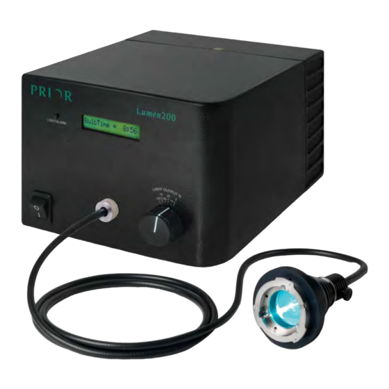
SECTION 3 Lumen200 Identifying your system. The Lumen200: Display Alarm reset Button Manual Shutter Control Collimator Power Switch Liquid Light Guide Microscope Adaptor connection Liquid Light Guide Light Guide Protective Locking Nut Quartz window Focus Locking Ring Microscope Adapter Fig 1 - The Liquid Light Guide Fig 2 –... -
Page 12: Installing Your System
• The bulb is delicate, handle with care. Instructions: 1. Do not connect the unit to the mains supply. (If the Lumen200 has been previously switched on, wait for 30 mins to allow bulb to cool). 2. Find a flat surface and place the Lumen200 upside down on the surface. - Page 13 Remove bulb from Carton : a. Open top of Carton b. Remove V-shaped Cardboard Holder c. Push Cardboard Flaps back d. Lift bulb out of carton. 4. Turn the bulb so that the cables and connector hang down into the bulb chamber. Plug the brown connector on the bulb into power socket in bulb housing;...
- Page 14 Data Connector Power Connector Bottom of the Bulb Figure 4.1d: Lumen Bulb. Fig 5 - The LM200B1-A Bulb 7. Lift the spring towards the bulb, as you do so the bulb will be pushed into the correct position, click the springs all the way into the Lamp Spring Restraints. (see Fig 6). Lamp Spring Restraint Lamp Spring...
-
Page 15: Connecting To The Microscope
3.2.2 Connecting to the Microscope Once the bulb is installed (see section 3.2.1), the Lumen200 is ready to be connected to the microscope. 1. Place the Lumen200 in a safe location and ensure none of the fan outputs are obstructed. -
Page 16: Starting Up The Lumen200
Working with the Lumen200 The Lumen200 is a manual light source. Attenuation of the light can be achieved by use of the manual shutter control knob on the front of the unit. Illumination can be set to 0%, 10%, 25%, 50%, 75% or 100% (Fig 8). -
Page 17: Shutting Down The Lumen200
This alarm can be silenced using the button situated to the left of the display panel on the front of the lumen. Once a bulb has reach 2000 hours the alarm will sound on power up of the Lumen200 until the bulb is changed. -
Page 18: Lumen200S
SECTION 4 Lumen200S Identifying your system. Fig 9 - The Lumen200S: Alarm reset Display Button Manual Shutter Control Power Socket Liquid Light Guide socket Power Switch Fig 10 - The Lumen200S Side Panel USB Socket Lamp On/Off RS232 TTL connector Connector Shutter Fuse Sockets... -
Page 19: Installing Your System
Lumen200S, Hex Key, Prior LM200B1-A Bulb Warning: • Only use Prior LM200B1-A bulbs, failure to do so may cause damage to the unit. • Do not touch the inside of the reflector of the bulb. • The bulb is delicate, handle with care. - Page 20 Remove bulb from Carton : a. Open top of Carton b. Remove V-shaped Cardboard Holder c. Push Cardboard Flaps back d. Lift bulb out of carton. 4. Turn the bulb so that the cables and connector hang down into the bulb chamber. Plug the brown connector on the bulb into power socket in bulb housing;...
- Page 21 Data Connector Power Connector Figure 4.1d: Lumen Bulb. Bottom of bulb Fig 13 - The LM200B1-A Bulb 7. Lift the spring towards the bulb, as you do so the bulb will be pushed into the correct position, click the springs all the way into the Lamp Spring Restraints. (see Figure 4.1e). Lamp Spring Restraint Lamp Spring...
-
Page 22: Connecting To The Microscope
Data Connector Fig 15 - The Data Connector 4.2.2 Connecting to the Microscope Once the bulb is installed (see section 4.2.1), the Lumen200S is ready to be connected to the microscope. 1. Place the Lumen200S in a safe location and ensure none of the fan outputs are obstructed. 2. -
Page 23: Connecting Your Lumen200S To A Pc
The Lumen200S can be controlled directly from a PC without the need of an external controller such as an OptiScan or ProScan. The Lumen200S will emulate a Prior Proscan controller with one shutter connected, and can be set up in 3 party software this way. - Page 24 When prompted select No, not at this time, then click NEXT. Fig 16 Select “Install from a list or specific location (advanced)” Fig 17 P r i o r S c i e n t i f i c...
- Page 25 Browse to the location of Eval232R, click NEXT. Fig 18 Fig 19 The Eval232R folder can be found in the SDK. This can be downloaded from www.prior.com. Fig 20 Contents of SDK. L u m e n 2 0 0 / S / P r o...
- Page 26 Fig 21 Click Finish. P r i o r S c i e n t i f i c...
-
Page 27: Connecting Your Lumen200S To An Optiscan Or Proscan System
4.2.4 Connecting your Lumen 200S to an OptiScan or ProScan System The Lumen 200S can work together with a Proscan or Optiscan controller assuming you have an active shutter connection, see Fig 22. 1. Connect Shutter Cntlr port on the Lumen200S to the Shutter port on the ProScan or OptiScan II system using the cables provided. -
Page 28: Starting Up The Lumen200S
Starting Up the Lumen 200S Warning: Do not power up the lumen without the light guide attached to both the Lumen200S and Microscope. Only power up the Lumen200S when it is installed on a level surface. 1 Ensure the light guide is attached to both the Lumen200S and Microscope. 2 Connect the power cable to the Lumen200S. -
Page 29: Using A Lumen200S As A Standalone Light Source
The Lumen200S shutter can be controlled via the OptiScan / Proscan controllers. Connect the Lumen200S to the shutter port of the Prior controller using a standard Prior shutter cable. The Prior controller can be controlled via the PC with either of the following connections, USB or RS232. -
Page 30: Shutting Down The Lumen200S
Shutting down the Lumen200S The following warnings apply as damage to the bulb may result if instructions not followed. Warning: Do not shut the unit down within 10 minutes of powering up the unit. Warning: After shutting down the unit, allow 10 minutes before re-powering up or changing the bulb. -
Page 31: Rs232 Command Set For Lumen200S
4 . 7 RS232 Command Set for Lumen200S A description of how to connect to the ProScan or OptiScan systems is supplied in the OptiScan II and ProScan II manual. The following is the RS232 commands applicable to the Lumen 200Pro. 4.7.1 General Commands for the Lumen 200S when connected to the PC Command Arguments... - Page 32 BULBTIME None Text string Returns the bulb lifetime as shown below; HOURS = 20 MINUTES = 30 Showing bulb lifetime of 20 hours and 30 minutes. UNIT None Text String Returns the status of the Lumen200S UNIT = 1 UNIT = O For Bulb ON For Bulb OFF UNIT...
-
Page 33: General Commands For The Lumen200S When Connected Via
4.7.2 General Commands for the Lumen 200S when connected via OptisScan / ProScan Controllers Command Argument s Response Description (All end with <cr>) s,c[,t] Opens or closes the shutter s (value ‘1’ ‘2’ or ‘3’), if c is 0 the shutter is opened, If shutter s is not fitted E,20 will 1 it is closed. -
Page 34: Lumen200Pro
SECTION 5 Lumen200PRO Identifying your system. Alarm reset Display Button Power Socket Liquid Light Guide Power Switch socket Fig 24 – The Lumen200Pro Fuse Sockets Filter Wheel connector Shutter /Light Atttenuation Lamp On/Off connector connector Power Socket Fig 25 – The Lumen200Pro Side Panel P r i o r S c i e n t i f i c... -
Page 35: Installing Your System
Lumen200Pro, Hex Key, Prior LM200B1-A Bulb Warning: • Only use Prior LM200B1-A bulbs, failure to do so may cause damage to the unit. • Do not touch the inside of the reflector of the bulb. • The bulb is delicate, handle with care. - Page 36 Remove bulb from Carton : a. Open top of Carton b. Remove V-shaped Cardboard Holder c. Push Cardboard Flaps back d. Lift bulb out of carton. 11. Turn the bulb so that the cables and connector hang down into the bulb chamber. Plug the brown connector on the bulb into power socket in bulb housing;...
- Page 37 Data Connector Power Connector Figure 4.1d: Lumen Bulb. Bottom of bulb Fig 28 – The LM200B1-A Bulb 14. Lift the spring towards the bulb, as you do so the bulb will be pushed into the correct position, click the springs all the way into the Lamp Spring Restraints. (See Figure 29). Lamp Spring Restraint Lamp Spring...
-
Page 38: Connecting To The Microscope
58mm. 4. Tighten the connector unit resistance is felt, the light guide is now firmly held in the Lumen200 Pro connector. Locate the collimating lens supplied to attach the light guide onto the microscope, loosen the screw on the back of the collimating lens. Firmly push the light guide into the hole ensuring it has reached it end stop and tighten the screw. -
Page 39: Connecting Your Lumen200Pro To An Optiscan Or Proscan System
5.2.3 Connecting your Lumen200Pro to a OptiScan or ProScan System The Lumen200Pro requires two filter wheel connections to a ProScan II or OptiScan II system. Connecting your system: 1 Switch off the ProScan or OptiScan II controller. 2. Connect Filter Wheel, Shutter port and Lamp ON/OFF (Optional) on the Lumen to the Filter 1 and Filter 2 and Shutter port on the ProScan or OptiScan II system using the cables provided. -
Page 40: Connecting Your Lumen200Pro To An Prior Pci Controller
5.2.4 Connecting your Lumen 200Pro to Prior PCI controller The Lumen200Pro requires two filter wheel connections to a Prior PCI system. Connecting your system: 1. Switch off the PCI controller/computer. 2. Connect the Attenuator/shutter to “FILTER 1” using the cables provided. -
Page 41: Changing Filters In The Filter Wheel
Changing Filters in the Filter Wheel The filter wheel can hold up to 6, 25mm filters; these are held in position using the standard Prior locking ring. Changing a Filter: Equipment required: Lumen200Pro, Filter, Prior Filter block tool, flat head screw driver. - Page 42 5. Lift the top of the unit, applying particular pressure to the front right corner to disconnect the internal connector. See Fig 32. Filter Wheel Internal Connector Fig 33 – The LumenPro200 Filter Wheel Compartment It is important to try and lift the cover from the Lumen200Pro as straight up as possible. This makes it easier to replace as it minimizes the stress on the internal connector.
-
Page 43: Starting Up The Lumen200Pro
8. Remove the old filter; replace the new filter taking care not to place finger prints on the filter. 9. Using the Prior Filter block tool screw the filter ring to hold the filter. Be careful; not to over tighten the filter ring; some filters will expand when heated by the light. -
Page 44: Working With The Lumen200Pro
Proscan or Optiscan controller. 5.4.1 Using a Lumen200Pro as a standalone light source It is not possible to use the Lumen200Pro as a standalone light source without a Prior controller. 5.4.3 Using a Lumen200Pro with PC and OptiScan/ProScan Controllers The Lumen200Pro can be controlled via the OptiScan / Proscan controllers using a standard Prior filter wheel and shutter cables. -
Page 45: When To Change The Bulb
When to Change the bulb The Lumen200Pro Bulb is installed with a timer chip which counts the hours that specific bulb has been activated. Once the bulb reaches the recommended lifetime of 2000 hours, an alarm will sound on the lumen. It is recommended that the bulb is changed at this point. This alarm can be silenced using the button situated to the left of the display panel on the front of the Lumen200Pro. - Page 46 6.3 RS232 Command Set A description of how to connect to the ProScan or OptiScan systems is supplied in the OptiScan II and ProScan II manual. The following is the RS232 commands applicable to the Lumen 200Pro. General Commands for identifying the Lumen200Pro. Identify which Filter Wheel port the Shutter and Filter Wheel are connected to using the “?”...
- Page 47 None Text string Reports information about the peripherals currently connected to the controller. The information end is always a line saying END This allows for the addition of extra fields of information without effecting application software. Users should always read lines in until the END is seen. A typical response is shown below OPTISCAN INFORMATION DRIVE CHIPS 11111...
- Page 48 The filter wheel installed in the Lumen Pro accepts the following commands. Command Arguments Response Description (All end with <cr>) w, f if f = F the If f is a number move filter wheel w to filter position f. current if f is a ‘N’...
- Page 49 Lumen 200Pro Standard Shutter Commands. The Lumen 200Pro Shutter accepts the standard commands for a Filter Wheel, Position 1-10 provide a standard range of light output from 0-100%. Command Arguments Response Description (All end with <cr>) w, f if f = F the If f is a number move filter wheel w to filter position f.
- Page 50 Report the current filter wheel w maximum speed setting m w, m Sets the current filter wheel w maximum speed to m. Range is 1 to 100 Command Arguments Response Description (All end with <cr>) P r i o r S c i e n t i f i c...
- Page 51 The following are a list of commands specific to the Lumen 200Pro. Command Arguments Response Description (All end with <cr>) LIGHT Reports a the output of light from the shutter in %. The command automatically locates LGG_SHUTTER. (Liquid Light Guide Shutter) Error 20 reported if no shutter detected.
-
Page 52: Error Codes
6.1.1 Error Codes If a command is not valid a response of “E,n” is returned the n specifying an error type as listed below. Machine or human readable messages are chosen using the ERROR Command. ERROR ERROR DESCRIPTION CODE NO STAGE NOT IDLE NO DRIVE STRING PARSE... -
Page 53: Troubleshooting
Under Temp Bulb area under Check unit is Fault temperature above 10 contact Prior. CHANGE Bulb reach 2000hr Yes, Change bulb. BULB lifetime limit Hold button for 5-10s L u m e n 2 0 0 / S / P r o... -
Page 54: Troubleshooting
Suggested Solutions: • Confirm unit is plugged in and there are no error codes on front display. • Confirm that the light output knob is not rotated to the 0% position (Lumen200 & Lumen200S). • Check shutter position (Lumen200S & Lumen200PRO only) position to confirm if it is in the fully closed position. - Page 55 Alarm sounds every time Lumen200 /S /Pro is turned on. Suggested Solution: • Check display on front of Lumen200 /S /Pro for error message. Check to see if the bulb has exceeded the recommended lifetime. • Check the display on the front of the Lumen200 /S /Pro for error message. Check to see if fan vents are covered or blocked.
- Page 56 Place the towels and any container used in the polythene bag and seal it. o Place the first bag in second polythene bag and seal it. o Pack the bag in a cardboard box and return it to Prior Scientific Instruments Ltd for disposal.
-
Page 57: Replacements Parts
SECTION 8 REPLACEMENT PARTS Description Part Number Prior Bulb LM200B1-A Fuse W3814 Liquid Light Guide LM587 Filter Wheel Cable HF300 Filter Changing Tool LM589 Adapters Olympus Adaptor (BX series) LM10OL Olympus Adaptor (IX series) LM10IX Zeiss Adaptor (Axio series) LM10ZS... -
Page 58: Returns And Repairs
Prior Scientific office before returning any equipment. For North and South America contact Prior Scientific Inc., for Japan contact Prior KK, for Germany, Austria and Switzerland contact Prior GmbH and for the all other countries contact Prior Scientific Instruments Limited on the telephone numbers shown below.
Need help?
Do you have a question about the Lumen200 and is the answer not in the manual?
Questions and answers