Table of Contents
Advertisement
Quick Links
Evaluating the ADAU1860 Three ADCs, One DAC, Low Power Codec with Audio DSPs
EVALUATION KIT CONTENTS
EVAL-ADAU1860EBZ evaluation board
►
USB cable with micro USB plug
►
mIDAS-Link emulator
►
DOCUMENTS NEEDED
ADAU1860
data sheet
►
EVAL-ADAU1860EBZ user guide
►
GENERAL DESCRIPTION
This user guide explains the design and setup of the EVAL-
ADAU1860EBZ evaluation board.
The EVAL-ADAU1860EBZ provides access to all the analog and
digital inputs and outputs on the ADAU1860. The ADAU1860 core
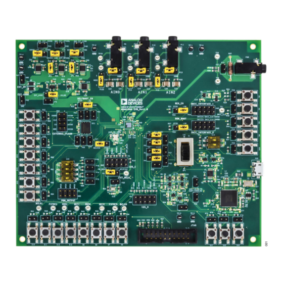
EVAL-ADAU1860EBZ BOARD PHOTOGRAPH
Analog Devices is in the process of updating documentation to provide terminology and language that is culturally appropriate. This is a process
with a wide scope and will be phased in as quickly as possible. Thank you for your patience.
PLEASE SEE THE LAST PAGE FOR AN IMPORTANT
WARNING AND LEGAL TERMS AND CONDITIONS.
User Guide | EVAL-ADAU1860
is controlled by Analog Devices, Inc., Lark Studio
interfaces to the EVAL-ADAU1860EBZ via a USB connection. In
addition, users can communicate and debug with the Tensilica HiFi
3z DSP core through the JTAG port by using the mIDAS-Link
emulator. The
software development kit (SDK)
Analog Devices for code development.
The EVAL-ADAU1860EBZ can be powered by the USB bus or by a
single 5 V supply. These supply options are regulated to the voltag-
es required on the EVAL-ADAU1860EBZ. The printed circuit board
(PCB) is a 4-layer design, with a ground plane and a power plane
on the inner layers. The EVAL-ADAU1860EBZ contains connectors
for external microphones and speakers. The master clock can be
provided externally or by the on-board 24.576 MHz oscillator.
Figure 1.
UG-2017
™
software, which
is also provided by
Rev. 0 | 1 of 26
Advertisement
Table of Contents

Subscribe to Our Youtube Channel
Related Manuals for Analog Devices EVAL-ADAU1860


Summary of Contents for Analog Devices EVAL-ADAU1860
-
Page 1: Evaluation Kit Contents
Figure 1. Analog Devices is in the process of updating documentation to provide terminology and language that is culturally appropriate. This is a process with a wide scope and will be phased in as quickly as possible. Thank you for your patience. -
Page 2: Table Of Contents
User Guide EVAL-ADAU1860 TABLE OF CONTENTS Evaluation Kit Contents......... 1 Using the Evaluation Board........9 Documents Needed..........1 Power Supply............. 9 General Description..........1 Control Port............10 EVAL-ADAU1860EBZ Board Photograph..... 1 Codec System..........11 Evaluation Board Block Diagram......3 Audio Inputs and Outputs......... 11 Setting Up the Evaluation Board...... -
Page 3: Evaluation Board Block Diagram
User Guide EVAL-ADAU1860 EVALUATION BOARD BLOCK DIAGRAM Figure 2. EVAL-ADAU1860EBZ Board Block Diagram analog.com Rev. 0 | 3 of 26... -
Page 4: Setting Up The Evaluation Board
User Guide EVAL-ADAU1860 SETTING UP THE EVALUATION BOARD INSTALLING THE LARK STUDIO SOFTWARE INSTALLING THE USB DRIVERS Download and install the latest version of Lark Studio by completing If the USB interface is not recognized by the Lark Studio software... -
Page 5: Setting Up Communication In Software
User Guide EVAL-ADAU1860 SETTING UP COMMUNICATION IN SOFTWARE CREATING A BASIC SIGNAL FLOW POWERING UP THE EVALUATION BOARD To create a basic signal flow in LARK Studio, follow these steps: To power up the EVAL-ADAU1860EBZ evaluation board, connect the ribbon cable to P22 of the EVAL-ADAU1860EBZ. - Page 6 User Guide EVAL-ADAU1860 SETTING UP COMMUNICATION IN SOFTWARE Figure 4. Connect with EVAL-ADAU1860EBZ Configure the Register Control, FastDSP, and EQ settings on 1. Select Hibernate1, BLOCKS_ON, and CM_BST_ON in the the left navigation panel. Lark Register Control has multiple tabs CHIP_PWR block in the Power tab, and then click Write (see that control different sections of the ADAU1860.
- Page 7 User Guide EVAL-ADAU1860 SETTING UP COMMUNICATION IN SOFTWARE Figure 5. Register Configurations If FastDSP is required in the project, a schematic must be created If the equalizer is required in the project, a configuration of the with the desired path for the...
- Page 8 User Guide EVAL-ADAU1860 SETTING UP COMMUNICATION IN SOFTWARE Figure 6. FastDSP Schematic Configuration analog.com Rev. 0 | 8 of 26...
-
Page 9: Using The Evaluation Board
User Guide EVAL-ADAU1860 USING THE EVALUATION BOARD 3. Connecting the isolated external power supply to P42 for AVDD POWER SUPPLY and HPVDD, P43 for IOVDD, P45 for HPVDD_L, and P46 for Power can be supplied to the EVAL-ADAU1860EBZ in one of three DVDD. -
Page 10: Control Port
User Guide EVAL-ADAU1860 USING THE EVALUATION BOARD CONTROL PORT The EVAL-ADAU1860EBZ is configured to serial peripheral inter- face (SPI) mode by default. To operate the codec in I C or universal asynchronous receiver/transmitter (UART) mode, see Table Table 3. Control Port Jumper and Switch (S1) Settings... -
Page 11: Codec System
User Guide EVAL-ADAU1860 USING THE EVALUATION BOARD CODEC SYSTEM Table 5. ADC Mode Jumper Settings ADC No. Mode Jumper Settings Clock Option ADC0 Differential Pin 1 to Pin 2 of P104, and Pin 1 to Pin 2 of P105 The EVAL-ADAU1860EBZ has three options for providing a master... -
Page 12: Serial Audio Interface
User Guide EVAL-ADAU1860 USING THE EVALUATION BOARD SERIAL AUDIO INTERFACE OTHER INTERFACES Serial audio signals in I S, left justified, right justified, or time Other interfaces include the following: division multiplexed (TDM) format are available via the serial audio JTAG ►... -
Page 13: Hardware Description
User Guide EVAL-ADAU1860 HARDWARE DESCRIPTION JUMPERS Table 9 lists the connector and jack descriptions. Table 9. Connector and Jack Description Reference Designator Functional Name Description ADDR1_MOSI/UART_RX Used to connect I C Address 1 and SPI data input to the ADAU1860, or to connect UART data receiver to the ADAU1860. - Page 14 User Guide EVAL-ADAU1860 HARDWARE DESCRIPTION Table 9. Connector and Jack Description Reference Designator Functional Name Description DMIC Interface 1 Header that allows the external digital microphones to be connected to the EVAL-ADAU1860EBZ. EXT_HPVDD_L Used to connect the external HPVDD_L supply to the EVAL- ADAU1860EBZ.
-
Page 15: Evaluation Board Schematics And Artwork
User Guide EVAL-ADAU1860 EVALUATION BOARD SCHEMATICS AND ARTWORK Figure 7. EVAL-ADAU1860EBZ Schematics, Page 1 analog.com Rev. 0 | 15 of 26... - Page 16 User Guide EVAL-ADAU1860 EVALUATION BOARD SCHEMATICS AND ARTWORK Figure 8. EVAL-ADAU1860EBZ Schematics, Page 2 analog.com Rev. 0 | 16 of 26...
- Page 17 User Guide EVAL-ADAU1860 EVALUATION BOARD SCHEMATICS AND ARTWORK Figure 9. EVAL-ADAU1860EBZ Schematics, Page 3 analog.com Rev. 0 | 17 of 26...
- Page 18 User Guide EVAL-ADAU1860 EVALUATION BOARD SCHEMATICS AND ARTWORK Figure 10. EVAL-ADAU1860EBZ Schematics, Page 4 analog.com Rev. 0 | 18 of 26...
- Page 19 User Guide EVAL-ADAU1860 EVALUATION BOARD SCHEMATICS AND ARTWORK Figure 11. EVAL-ADAU1860EBZ Schematics, Page 5 analog.com Rev. 0 | 19 of 26...
- Page 20 User Guide EVAL-ADAU1860 EVALUATION BOARD SCHEMATICS AND ARTWORK Figure 12. EVAL-ADAU1860EBZ Schematics, Page 6 analog.com Rev. 0 | 20 of 26...
- Page 21 User Guide EVAL-ADAU1860 EVALUATION BOARD SCHEMATICS AND ARTWORK Figure 13. EVAL-ADAU1860EBZ Schematics, Page 7 Figure 14. EVAL-ADAU1860EBZ Schematics, Page 8 analog.com Rev. 0 | 21 of 26...
- Page 22 User Guide EVAL-ADAU1860 EVALUATION BOARD SCHEMATICS AND ARTWORK Figure 15. EVAL-ADAU1860EBZ Schematics, Page 9 analog.com Rev. 0 | 22 of 26...
- Page 23 User Guide EVAL-ADAU1860 EVALUATION BOARD SCHEMATICS AND ARTWORK Figure 16. EVAL-ADAU1860EBZ Layer 1, Component Side Figure 18. EVAL-ADAU1860EBZ Layer 3, Power Plane Figure 17. EVAL-ADAU1860EBZ Layer 2, Ground Plane Figure 19. EVAL-ADAU1860EBZ Layer 4, Bottom Side analog.com Rev. 0 | 23 of 26...
-
Page 24: Ordering Information
User Guide EVAL-ADAU1860 ORDERING INFORMATION BILL OF MATERIALS Table 10. Reference Description Manufacturer Model Number Microprocessors supervisory circuit in 4-lead SOT-143, logic Analog Devices ADM811TARTZ low RESET output BCLK0, BCLK1, FSYNC0, FSYNC1, PCB connector, test points, white Keystone 5002 SDI0, SDI1, SDO0, SDO1, TP1 to TP9,... - Page 25 User Guide EVAL-ADAU1860 ORDERING INFORMATION Table 10. Reference Description Manufacturer Model Number R3 to R5, R20, R21, R25, R27, and R75 10 kΩ resistors, SMD, 1%, 1/10 W, 0603, AEC-Q200 Panasonic ERJ-3EKF1002V to R89 49.9 Ω resistors, SMD, 1%, 1/10 W, 0603, AEC-Q200...
- Page 26 Evaluation Board until you have read and agreed to the Agreement. Your use of the Evaluation Board shall signify your acceptance of the Agreement. This Agreement is made by and between you (“Customer”) and Analog Devices, Inc. (“ADI”), with its principal place of business at Subject to the terms and conditions of the Agreement, ADI hereby grants to Customer a free, limited, personal, temporary, non-exclusive, non-sublicensable, non-transferable license to use the Evaluation Board FOR EVALUATION PURPOSES ONLY.
Need help?
Do you have a question about the EVAL-ADAU1860 and is the answer not in the manual?
Questions and answers