Table of Contents
Advertisement
Quick Links
Evaluating the AD4050/AD4052 Compact, Low Power, 12-Bit/16-Bit, 2 MSPS Easy Drive SAR ADCs
FEATURES
Full featured evaluation boards for the AD4050 and AD4052 with
►
a USB power solution
Single differential channel and common-mode input available
►
through SMA connectors
Out of the box evaluation experience with the SDP-K1
►
PC software (ACE plugin) for control and data analysis of the
►
time and frequency domains
Compatible with other Arduino form factor controller boards
►
EQUIPMENT NEEDED
PC with Windows 7 or later operating system
►
SDP-K1 controller board and accompanying USB cable
►
Precision signal generator (see the
►
section)
SOFTWARE NEEDED
ACE
evaluation software
►
AD4050/AD4052
ACE plugin
►
Software Installation Procedure
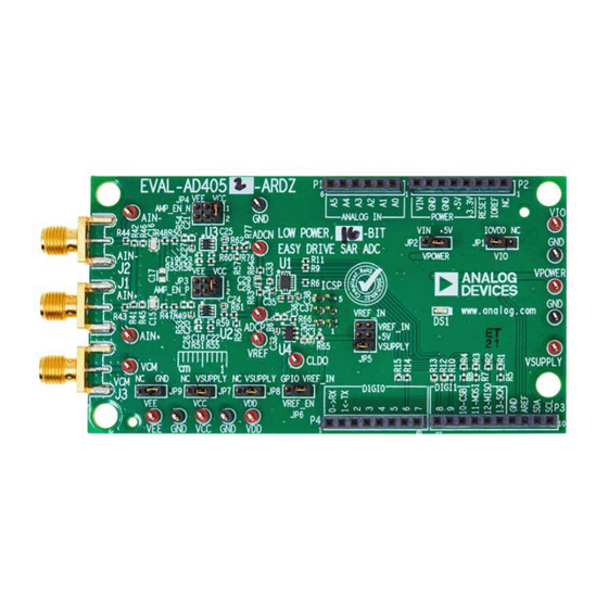
EVALUATION BOARD PHOTOGRAPH
PLEASE SEE THE LAST PAGE FOR AN IMPORTANT
WARNING AND LEGAL TERMS AND CONDITIONS.
Evaluation Board Hardware
from the plugin manager (see the
section)
Figure 1. EVAL-AD4052-ARDZ Evaluation Board Photograph
User Guide | EVAL-AD4050/AD4052
EVALUATION BOARD KIT CONTENTS
EVAL-AD4050-ARDZ/EVAL-AD4052-ARDZ evaluation board
►
USEFUL LINKS AND RESOURCES
AD4050
product page
►
AD4052
product page
►
EVAL-AD4050-ARDZ
►
EVAL-AD4052-ARDZ
►
ACE Installer
►
GENERAL DESCRIPTION
The EVAL-AD4050-ARDZ and EVAL-AD4052-ARDZ evaluation
boards enable quick and easy evaluation of the performance and
features of the AD4050 or the AD4052, respectively. The AD4050
and AD4052 are compact, low power, 12-bit or 16-bit (respectively)
Easy Drive successive approximation register (SAR) analog-to-digi-
tal converters (ADCs).
The primary controller board for the EVAL-AD4050-ARDZ/EVAL-
AD4052-ARDZ is the SDP-K1. The EVAL-AD4050-ARDZ/EVAL-
AD4052-ARDZ conform to the Arduino
and electrical standards to interface with the SDP-K1, in addition to
various software development kits from other manufacturers.
The AD4050/AD4052 evaluation solutions include the AD4050/
AD4052 industrial input and output (IIO) firmware application driv-
ers for device configuration and ADC data capture and the AD4050/
AD4052 ACE plugin graphical user interface (GUI) for performance
evaluation.
UG-2222
product page
product page
®
Uno Shield mechanical
Rev. A | 1 of 19
Advertisement
Table of Contents

Subscribe to Our Youtube Channel
Related Manuals for Analog Devices EVAL-AD4050-ARDZ


Summary of Contents for Analog Devices EVAL-AD4050-ARDZ
-
Page 1: Features
AD4052 are compact, low power, 12-bit or 16-bit (respectively) Easy Drive successive approximation register (SAR) analog-to-digi- SOFTWARE NEEDED tal converters (ADCs). evaluation software ► The primary controller board for the EVAL-AD4050-ARDZ/EVAL- AD4050/AD4052 ACE plugin from the plugin manager (see the ► AD4052-ARDZ is the SDP-K1. The EVAL-AD4050-ARDZ/EVAL-... -
Page 2: Table Of Contents
User Guide EVAL-AD4050/AD4052 TABLE OF CONTENTS Features..............1 Power Supplies..........8 Equipment Needed..........1 Voltage Reference Circuit........9 Software Needed...........1 Analog Front End (AFE)........9 Evaluation Board Kit Contents.......1 Hardware and Link Options......12 Useful Links and Resources........1 Evaluation Board Software........13 General Description..........1 Software Installation Procedure....... -
Page 3: Quick Start Guide
SDP-K1 User Guide for more information). The DS1 light- loading the ACE software and the AD4050/AD4052 ACE plugin. emitting diode (LED) illuminates when the EVAL-AD4050-ARDZ/ EVAL-AD4052-ARDZ are receiving power from the SDP-K1 and is HARDWARE SETUP generating the +3.3 V rail to the on-board AD4050/AD4052 and its companion circuitry. - Page 4 User Guide EVAL-AD4050/AD4052 QUICK START GUIDE Figure 5. EVAL-AD4052-ARDZ on DC Jack Power Before launching the AD4050/AD4052 ACE plugin, it is recom- mended to connect a precision signal source or signal generator to the analog input Subminiature Version A (SMA) connectors to drive the AD4050/AD4052 inputs into their specified operating ranges.
-
Page 5: Evaluation Board Hardware
AD4050/ circuitry includes the following: AD4052 and are not necessarily applicable to all system designs AD4050BCPZ/AD4052BCPZ: the 14-lead LFCSP model of the and use cases. ► AD4050/AD4052 Figure 7. EVAL-AD4050-ARDZ/EVAL-AD4052-ARDZ Simplified Block Diagram analog.com Rev. A | 5 of 19... - Page 6 User Guide EVAL-AD4050/AD4052 EVALUATION BOARD HARDWARE Figure 8. EVAL-AD4052-ARDZ Evaluation Board Circuitry Locations Top Side Figure 9. EVAL-AD4052-ARDZ Evaluation Board Circuitry Locations Bottom Side analog.com Rev. A | 6 of 19...
-
Page 7: Connectors And Sockets
(P3 and P4). The digital pin function assignment CONNECTORS AND SOCKETS conforms to the Arduino Uno standard. The digital headers and The connectors and sockets on the EVAL-AD4050-ARDZ/EVAL- signals are primarily on page 3 of both the EVAL-AD4050-ARDZ... -
Page 8: Power Supplies
User Guide EVAL-AD4050/AD4052 EVALUATION BOARD HARDWARE the Arduino Uno power header (P2 on the EVAL-AD4050-ARDZ/ POWER SUPPLIES EVAL-AD4052-ARDZ). The JP2 jumper selects between the +5 V or VIN as the input source of the ADP7118 that supplies the 3.3 V analog rail. By default, +5 V is selected, as 5 V has enough headroom for the ADP7118 to generate a regulated 3.3 V output. -
Page 9: Voltage Reference Circuit
► Figure 12. Default Amplifier Circuit Simplified Schematics Analog Inputs section provides instructions for interfacing the signal generator and the SMA inputs on the EVAL-AD4050-ARDZ/ Analog Inputs EVAL-AD4052-ARDZ. This section provides guidance for driving the EVAL-AD4050- By default, the amplifiers are configured as unity-gain buffers, but... - Page 10 The following provides some examples for hooking up differ- VIN,diff is 2.5 V peak or 5 V p-p, and VCM is 1.25 V DC. ent types of signal generators to the EVAL-AD4050-ARDZ/EVAL- AD4052-ARDZ. All of these examples ignore the output impedance...
- Page 11 User Guide EVAL-AD4050/AD4052 EVALUATION BOARD HARDWARE Figure 16. Biased Differential Signal Generator Example analog.com Rev. A | 11 of 19...
-
Page 12: Hardware And Link Options
EVALUATION BOARD HARDWARE HARDWARE AND LINK OPTIONS Table 4 details each of the optional jumper and link options present on the EVAL-AD4050-ARDZ/EVAL-AD4052-ARDZ with a brief description of the default and secondary positions and functions. Table 4. Jumper and Link Options and Descriptions... -
Page 13: Evaluation Board Software
Download the evaluation software from the EVAL-AD4050- ARDZ or the EVAL-AD4052-ARDZ evaluation kit page. Install the software on a PC before using the EVAL-AD4050-ARDZ/EVAL- AD4052-ARDZ kit. Download the AD4050/AD4052 ACE plugin from the EVAL-AD4050-ARDZ/EVAL-AD4052-ARDZ product page or from the ACE plugin manager. -
Page 14: Installing The Ad4050/Ad4052 Ace Plugin
To start the ACE evaluation software, open the Windows Start Figure 24. AD4052 Plugin Board View menu and click Analog Devices > ACE. The software window continues loading until the software recognizes the EVAL-AD4050- ARDZ/EVAL-AD4052-ARDZ. When the software recognizes the... -
Page 15: Chip View
User Guide EVAL-AD4050/AD4052 EVALUATION BOARD SOFTWARE CHIP VIEW Hover over the AD4050/AD4052 symbol in the Board View and double click to enter the Chip View (see Figure 25). Figure 25. AD4052 Plugin Chip View analog.com Rev. A | 15 of 19... -
Page 16: Analysis View
User Guide EVAL-AD4050/AD4052 EVALUATION BOARD SOFTWARE The Waveform graph shows each successive sample of the ANALYSIS VIEW AD4050/AD4052 output. The user can zoom in on and pan over the Click Proceed to Analysis to navigate to the AD4050/AD4052 Waveform graph using the embedded waveform tool bar located Analysis window. - Page 17 User Guide EVAL-AD4050/AD4052 EVALUATION BOARD SOFTWARE The Histogram graph displays the number of hits per code within Histogram Tab the sampled data. Use this graph for DC analysis as it indicates the The Histogram tab contains the histogram graph and the Results noise performance of the device.
- Page 18 User Guide EVAL-AD4050/AD4052 EVALUATION BOARD SOFTWARE signal-to-noise ratio (SNR) and other noise performance measure- FFT Tab ments, such as the signal-to-noise-and-distortion (SINAD), Dynam- The FFT tab displays fast Fourier transform (FFT) information for ic Range, noise density (Noise/Hz), and peak harmonic or spuri- the last batch of samples gathered (see Figure 28).
- Page 19 Evaluation Board until you have read and agreed to the Agreement. Your use of the Evaluation Board shall signify your acceptance of the Agreement. This Agreement is made by and between you (“Customer”) and Analog Devices, Inc. (“ADI”), with its principal place of business at Subject to the terms and conditions of the Agreement, ADI hereby grants to Customer a free, limited, personal, temporary, non-exclusive, non-sublicensable, non-transferable license to use the Evaluation Board FOR EVALUATION PURPOSES ONLY.
Need help?
Do you have a question about the EVAL-AD4050-ARDZ and is the answer not in the manual?
Questions and answers