Table of Contents
Advertisement
Quick Links
One Technology Way • P.O. Box 9106 • Norwood, MA 02062-9106, U.S.A. • Tel: 781.329.4700 • Fax: 781.461.3113 • www.analog.com
Evaluating the
FEATURES
General-purpose evaluation board for the ADF4152HV,
including octave range VCO, loop filter, and TCXO
Contains the
ADF4152HV
frequency synthesizer (500 MHz to
5 GHz
Contains the
ADF5001
prescaler to allow optional connection
of external microwave VCOs without the need for an active
loop filter
Accompanying software allows complete control of
synthesizer functions from a PC
EVALUATION KIT CONTENTS
EVAL-ADF4152HVEB1Z
board
CD that includes
Self installing software that allows users to control the
board and exercise all functions of the device
Electronic version of the
Electronic version of the
EVAL-ADF4152HVEB1Z User Guide
Electronic version of the
ADDITIONAL EQUIPMENT
PC running Windows XP or more recent version
Power supply
Spectrum analyzer
Oscilloscope (optional)
PLEASE SEE THE LAST PAGE FOR AN IMPORTANT
WARNING AND LEGAL TERMS AND CONDITIONS.
ADF4152HV
ADF4152HV
data sheet
PLL Software Installation Guide
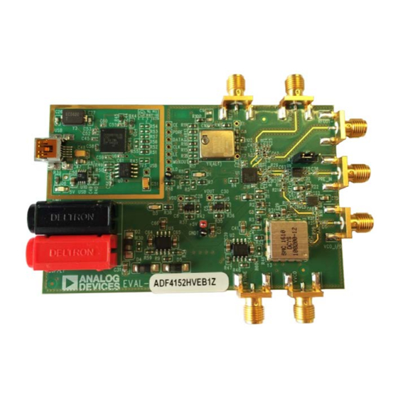
EVALUATION BOARD PHOTOGRAPH
Figure 1.
EVAL-ADF4152HVEB1Z User Guide
PLL Frequency Synthesizer
DOCUMENTS NEEDED
ADF4152HV
data sheet
EVAL-ADF4152HVEB1Z User Guide
PLL Software Installation Guide
REQUIRED SOFTWARE
Analog Devices
or higher)
GENERAL DESCRIPTION
This board is designed to allow the user to evaluate the perfor-
mance of the
ADF4152HV
loops (PLLs). Figure 1 shows the board, which contains the
ADF4152HV
synthesizer, loop filter, voltage controlled oscillator
(VCO) of 1 GHz to 2 GHz octave range and up to 28 V high
tuning voltage, reference temperature controlled crystal oscillator
(TCXO) of 25 MHz frequency for the reference input, power
supply connectors, and a radio frequency (RF) output. The
ADF5001
prescaler allows optional direct connection of external
microwave VCOs without the need for an active loop filter.
The evaluation kit also contains software that is compatible with
Windows® XP and later versions to allow easy programming of
the synthesizer.
The PC must have a USB port to program the device.
EVAL-ADF4152HVEB1Z
Rev. 0 | Page 1 of 20
ADF4152HV
family software (Version 4.4.0
frequency synthesizer for phase-locked
UG-963
Advertisement
Table of Contents

Subscribe to Our Youtube Channel
Related Manuals for Analog Devices EVAL-ADF4152HVEB1Z


Summary of Contents for Analog Devices EVAL-ADF4152HVEB1Z
-
Page 1: Features
EVAL-ADF4152HVEB1Z User Guide UG-963 One Technology Way • P.O. Box 9106 • Norwood, MA 02062-9106, U.S.A. • Tel: 781.329.4700 • Fax: 781.461.3113 • www.analog.com Evaluating the ADF4152HV PLL Frequency Synthesizer FEATURES DOCUMENTS NEEDED General-purpose evaluation board for the ADF4152HV, ADF4152HV... -
Page 2: Table Of Contents
UG-963 EVAL-ADF4152HVEB1Z User Guide TABLE OF CONTENTS Features ....................1 Input Signals...................4 Evaluation Kit Contents ..............1 Output Signals ................4 Additional Equipment ..............1 Default Operation Settings ............4 Documents Needed ................1 Additional Options ...............4 Required Software ................1 Phase Noise Measurement ............5 General Description ................. -
Page 3: Quick Start Guide
EVAL-ADF4152HVEB1Z User Guide UG-963 QUICK START GUIDE Follow these steps to quickly evaluate the ADF4152HV device: Run the Analog Devices ADF4152 family software. Select USB board (green) and ADF4152HV in the Select Install the Analog Devices ADF4152 family software (see... -
Page 4: Evaluation Board Hardware
UG-963 EVAL-ADF4152HVEB1Z User Guide EVALUATION BOARD HARDWARE EVAL-ADF4152HVEB1Z schematics are shown in Figure 8, The device is quite sensitive to impedance unbalance. If only Figure 9, Figure 10, and Figure 11. The silkscreen of the one port of the differential pair is used, the other must be evaluation board is shown in Figure 16. -
Page 5: Phase Noise Measurement
EVAL-ADF4152HVEB1Z User Guide UG-963 Prescaler for Microwave VCO PHASE NOISE MEASUREMENT The board contains the ADF5001, an 18 GHz divide by 4 With the default settings, in-band phase noise of close to prescaler, to interface a high frequency microwave VCO to the −101 dBc/Hz can be measured. -
Page 6: Evaluation Board Software
UG-963 EVAL-ADF4152HVEB1Z User Guide EVALUATION BOARD SOFTWARE The control software for the EVAL-ADF4152HVEB1Z accom- Confirm that ADF4xxx USB Adapter Board connected is panies the board on the CD included in the evaluation kit. To displayed at the bottom left of the window (see Figure 4). - Page 7 EVAL-ADF4152HVEB1Z User Guide UG-963 The Main Controls tab controls the PLL settings (see Figure 5). In the Sweep and Hop tab, set the device to sweep a range of frequencies or hop between two set frequencies. Use the Reference Frequency text box to set the correct reference frequency and the reference frequency divider.
-
Page 8: Evaluation And Test
UG-963 EVAL-ADF4152HVEB1Z User Guide EVALUATION AND TEST To evaluate and test the performance of the ADF4152HV, use the following procedure: If using a different VCO and loop filter than provided on the board, ensure that a VCO and loop filter are properly inserted on the board. -
Page 9: Evaluation Board Schematics And Artwork
EVAL-ADF4152HVEB1Z User Guide UG-963 EVALUATION BOARD SCHEMATICS AND ARTWORK Figure 8. Evaluation Board Schematic (Page 1) Rev. 0 | Page 9 of 20... - Page 10 UG-963 EVAL-ADF4152HVEB1Z User Guide Figure 9. Evaluation Board Schematic (Page 2) Rev. 0 | Page 10 of 20...
- Page 11 EVAL-ADF4152HVEB1Z User Guide UG-963 Figure 10. Evaluation Board Schematic (Page 3) Rev. 0 | Page 11 of 20...
- Page 12 UG-963 EVAL-ADF4152HVEB1Z User Guide Figure 11. Evaluation Board Schematic (Page 4) Rev. 0 | Page 12 of 20...
- Page 13 EVAL-ADF4152HVEB1Z User Guide UG-963 Figure 12. Layer 1 (Component Side) Rev. 0 | Page 13 of 20...
- Page 14 UG-963 EVAL-ADF4152HVEB1Z User Guide Figure 13. Layer 2 (Ground Plane) Rev. 0 | Page 14 of 20...
- Page 15 EVAL-ADF4152HVEB1Z User Guide UG-963 Figure 14. Layer 3 (Power Plane) Rev. 0 | Page 15 of 20...
- Page 16 UG-963 EVAL-ADF4152HVEB1Z User Guide Figure 15. Layer 4 (Solder Side) Rev. 0 | Page 16 of 20...
- Page 17 EVAL-ADF4152HVEB1Z User Guide UG-963 Figure 16. Evaluation Board Silkscreen Rev. 0 | Page 17 of 20...
-
Page 18: Bill Of Materials
UG-963 EVAL-ADF4152HVEB1Z User Guide BILL OF MATERIALS Table 1. Bill of Materials Reference Designator Value Description Manufacturer/Part Number Red test point Vero 20-313137 3V3_USB, 5V_USB Do not insert Red test point Not applicable AGND Black test point Vero 20-2137 2.2 nF... -
Page 19: Related Links
EVAL-ADF4152HVEB1Z User Guide UG-963 Reference Designator Value Description Manufacturer/Part Number R20, R21 68 Ω SMD resistor Multicomp MC 0.0625W 0402 1% 68R R23, R24 51 Ω SMD resistor Multicomp MC 0.063W 0402 51R 0 Ω 0402 SMD resistor Multicomp MC 0.0625W 0402 1% 0R R26, R27, R28 18 Ω... - Page 20 By using the evaluation board discussed herein (together with any tools, components documentation or support materials, the “Evaluation Board”), you are agreeing to be bound by the terms and conditions set forth below (“Agreement”) unless you have purchased the Evaluation Board, in which case the Analog Devices Standard Terms and Conditions of Sale shall govern. Do not use the Evaluation Board until you have read and agreed to the Agreement.
Need help?
Do you have a question about the EVAL-ADF4152HVEB1Z and is the answer not in the manual?
Questions and answers