
Related Manuals for Tuxedo TP9KF-TUX


Summary of Contents for Tuxedo TP9KF-TUX
- Page 1 TP9KF-TUX Two-Post Floor Plate Lift (Symmetric) 9,000 lbs. Capacity (2,250 lbs. Max per Arm) INSTALLATION & OPERATION MANUAL Mar 2019-A...
-
Page 2: Important Notes
DEFINITION Surface Mounted, Two-Post, Open Top Lift w/ Floor Plate, Hydraulic ‘chain-over’ Drive, 9,000 lbs. Capacity. The name / model numbers are designated below: · Model number TP9KF-TUX - Symmetric Swing Arm configuration BASIC SPECIFICATIONS Description Overall Overall Lifting... -
Page 3: General Information
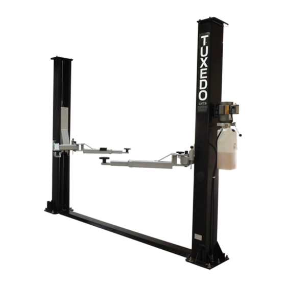
Every column comes with its cylinder, carriage, cables & chains, lifting arms, swivel pads, height extensions, hoses and ‘drive-over’ floor plate with the hardware box located in one of the columns. · The electric-hydraulic motor pump is packaged separately and banded to top of lift. Fig. 1 3 TP9KF-TUX Mar 2019-A... - Page 4 4 TP9KF-TUX Mar 2019-A...
-
Page 5: Installation Instructions
INSTALLATION INSTRUCTIONS STEP 1: (Selecting Site) Before installing your new lift, check the following: 1. LIFT LOCATION: Always use architects plans when available. Check layout dimension against floor plan requirements making sure that adequate space is available (Figs. 2, 3 & 4). Fig. - Page 6 Fig. 3 (Swing Arm & Column Layout) (134-5/8”) Fig. 4 (Column / Floor Layout) 6 TP9KF‐TUX Mar 2019‐A...
- Page 7 4. After the post locations are marked, use a chalk or crayon to make an outline of the posts on the floor at each location using the post base plates as a template. 5. Double check all dimensions and make sure that the layout is perfectly square. 7 TP9KF-TUX Mar 2019-A...
-
Page 8: Step 5: (Installing Offside Column)
STEP 4: (Installing MAIN COLUMN w/ Power Unit Bracket) 1. Before proceeding, double check measurements and make certain that the bases of each column are square and aligned with the chalk line. 2. Ensure Top Cap is pre-installed to the top of the Main column. Raise the column to a vertical position. 3. - Page 9 STEP 5: (Installing OFFSIDE COLUMN) Cont. 4. Using a tape measure, ensure the diagonal distance between the opposite corners of the base plates on the columns are within equal dimensions (+/-) 1/4” to ensure the lifting arms will be in square. 5.
- Page 10 5. Repeat above for the second cable. 6. Adjust each equalizer cable to approximately 1/2” side-to-side play. Ensure that each cable has equal tension. Check the carriage height to ensure both carriages are sitting on the same latch. 10 TP9KF-TUX Mar 2019-A...
- Page 11 STEP 8: (Installing / Routing HYDRAULIC HOSES & HYDRAULIC FITTINGS) 1. Install & connect hydraulic hoses & fittings as noted & shown below in (Figs. 14-16) along with the Exploded View #1 diagram on page 21. Note: Ensure Not To Overtighten Hydraulic & Hose Fittings!! a) Remove red cap plug from high pressure port on side of power unit’s valve block.
-
Page 12: Safety Notice
3. Install Arm Restraint mechanisms to each swing arm, as detailed below (Fig. 17). 4. Check for proper engagement for the arm restraints as the gear rack should fully engage the gear on the arm. SAFETY NOTICE! Fig. 17 12 TP9KF-TUX Mar 2019-A... - Page 13 For 208V-230V single phase, use 20 amp fuse. WARNING!! Never operate the motor in line voltage less than 208VAC as motor damage may occur. NOTE: TP9KF-TUX Lift model does not require or provide connection for Overhead Limit Switch Mechanism due to lift being ‘open top’...
- Page 14 3. If latches click out of sync, tighten the equalization cable on the Fig. 20 one that clicks first. THE LIFT IS NOW READY FOR USE. IMPORTANT! Read Safety & Operating Information on following pages before using lift. 14 TP9KF-TUX Mar 2019-A...
- Page 15 5. Before removing vehicle from lift area, position lift arms and supports to provide an unobstructed exit. WARNING: NEVER DRIVE OVER LIFT’S ARMS. Note: It is normal for an empty lift to lower slowly, it may be necessary to add weight. 15 TP9KF-TUX Mar 2019-A...
-
Page 16: Safety Procedures
The following periodic maintenance is the suggested minimum requirements and minimum intervals; accumulated hours or monthly period, whichever comes sooner. If you hear a noise or see any indication of impending failure - cease operation immediately – inspect, correct and / or replace parts as required. 16 TP9KF-TUX Mar 2019-A... -
Page 17: Responsibility Of The User
Change the hydraulic fluid. Good maintenance procedure makes it mandatory to keep hydraulic fluid clean. No hard fast rules can be established; operating temperature, type of service, contamination levels, filtration, and chemical composition of fluid should be considered. If operating in a dusty environment, shorter interval may be required. 17 TP9KF-TUX Mar 2019-A... - Page 18 / or capped until just prior to use. Air hoses can be used to clean fittings and other components. However, the air supply must be filtered and dry to prevent contamination. Contamination is the most frequent cause of malfunction or hydraulic equipment. 18 TP9KF-TUX Mar 2019-A...
-
Page 19: Troubleshooting
Carriage of the lift is dry and requires grease. Grease corners of columns. Cylinder pulley assembly or cable pulley assembly is not moving freely. Check and grease it. May have excessive wear on pins or cylinder yoke. Check and replace them. Seals are dry in hydraulic cylinder(s). 19 TP9KF-TUX Mar 2019-A... -
Page 20: Power Unit Priming
POWER UNIT PRIMING WARNING!! Failure to properly relieve pressure in the following steps can cause injury to personnel. 20 TP9KF-TUX Mar 2019-A... -
Page 21: Exploded View
EXPLODED VIEW #1 21 TP9KF‐TUX Mar 2019‐A... - Page 22 EXPLODED VIEW #2 22 TP9KF‐TUX Mar 2019‐A...
-
Page 23: Parts List
PARTS LIST ITEM Tux P/N M-Ref P/N DESCRIPTION TP9KF-TUX-001A TPF4-100-00 (A) Mainside Column TP9KF-TUX-001B TPF4-100-00 (B) Offside Column TP9KF-TUX-002 TPF4-100-10-05 Cable Pulley TP9KF-TUX-003 GB894.1-2000 D25 Circlip, D25 TP9KF-TUX-004 TPF4-100-12 Plastic Cover, Column TP9KF-TUX-006 GB5781-86 Bolt TP9KF-TUX-007 GB6170-86 TP9KF-TUX-008 GB97.2-85 Flat Washer... - Page 24 TP9KF-TUX-038 PU-2220V-L-H 220V Power Unit TP9KF-TUX-039 TT-6934-500-04KY Hyd. Pump Fitting TP9KF-TUX-040 O-Ring, Pump Fitting TP9KF-TUX-041 TT-6934-500-01NEW Hyd. Hose, Short TP9KF-TUX-042 TT-6834-500-01 Hyd. Hex Pipe Fitting TP9KF-TUX-043 Combined Washer, M14 TP9KF-TUX-044 TT-6934-500-06 Throttle Valve 44.1 TP9KF-TUX-044.1 TT-6934-500-07 Valve Insert 44.2 TP9KF-TUX-044.2...
-
Page 25: Limited Warranty
There is no other express warranty on the Tuxedo lifts and this warranty is exclusive of and in lieu of all other warranties, expressed or implied, including all warranties of merchantability and fitness for a particular purpose. To the fullest extent allowed by law, Tuxedo shall not be liable for loss of use, cost of cover, lost profits, inconvenience, lost time, commercial loss or other incidental or consequential damages.
Need help?
Do you have a question about the TP9KF-TUX and is the answer not in the manual?
Questions and answers