Advertisement
Quick Links
.
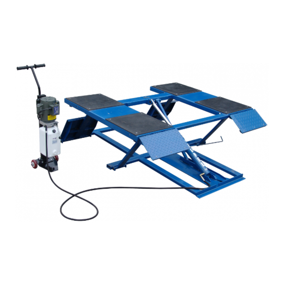
6,000
Easy frame lifting on padded runways. Great for wheel and brake work,
LB
tire and wheel changing as well as new car preparation.
L
-
OW
RISE
P
L
AD
IFT
6,000
.
Mid-rise models lift cars, vans and light-duty trucks. They are ideal for tire,
LB
wheel and brake related repairs, collision repair work and new car preparation.
M
-
L
ID
RISE
IFT
S
PECIFICATIONS
Lifting capacity
Overall width
Overall length
Maximum height
Low pad height
Lifting speed
Motor
Width between runways
Runway width
Collapsed height
Shipping weight
MR 6 K- 4 8
LR- 26 -PAD
6,000 lbs.
6,000 lbs.
73"
39
5
⁄
"- 57"
8
86"
96
1
⁄
"
2
26"- 30"
48
1
⁄
"- 54"
2
NA
7"
35 sec.
40 sec.
1hp/110 vac
1hp/110 vac
35"
NA
19"
NA
5"
4
3
⁄
"
4
955 lbs.
943 lbs.
Features:
6,000 lb. lifting capacity
Automatic safety locks
Low drive-over height
for approach of
low vehicles
High speed motor lifts
from 3"-26" in only
35 seconds
LR- 26 -PAD
2 sets of rubber
Low-rise
riser blocks
Pad lift
Features:
6,000 lb. lifting capacity
Portable trolley supports
pump and moves lift
Twin hydraulic cylinders
and scissors lift design
for maximum strength
MR 6 K- 4 8
Mid-rise lift
and stability
Easily adjustable sliding
radius arms
Automatic two-position
safety locks
Swivel pads come
standard. Optional
drop-in height adapters
are also available
Advertisement

Subscribe to Our Youtube Channel
Related Manuals for Tuxedo LR-26-PAD


Summary of Contents for Tuxedo LR-26-PAD
- Page 1 6,000 Easy frame lifting on padded runways. Great for wheel and brake work, tire and wheel changing as well as new car preparation. RISE Features: 6,000 lb. lifting capacity Automatic safety locks Low drive-over height for approach of low vehicles High speed motor lifts from 3”-26”...
- Page 2 LR-26-PAD 6000 lb Capacity Low-Rise Pad Lift ASSEMBLY & OPERATION INSTRUCTION MANUAL REV A-090413...
- Page 4 6,000 Easy frame lifting on padded runways. Great for wheel and brake work, tire and wheel changing as well as new car preparation. RISE Features: 6,000 lb. lifting capacity Automatic safety locks Low drive-over height for approach of low vehicles High speed motor lifts from 3”-26”...
- Page 5 There is no other express warranty on the Tuxedo lifts and this warranty is exclusive of and in lieu of all other warranties, expressed or implied, including all warranties of merchantability and fitness for a particular purpose.
-
Page 6: Installation Instruction
INSTALLATION INSTRUCTION STEP 1: (Selecting Site) Before installing your new lift, check the following: LIFT LOCATION: Always use architects plans when available. Check layout dimension against floor plan requirements making sure that adequate space is available. OVERHEAD OBSTRUCTIONS: The area where the lift is to be located should be free of overhead obstructions such as heaters, building supports, electrical lines etc. - Page 7 With the shims and anchor bolts in place, tighten by securing the nut to the base then turning 2-3 full turns clockwise. STEP 4: (Installing the MOTOR PUMP) 1. Assembly the wheel trolley according to Fig18. 2. Mount the motor pump (power unit) to the wheel trolley using bolts, nuts and washers supplied.(Fig. Fig.
- Page 8 Fig. 10 Fig. 11 Cycle the lift up and down several times to insure all air is removed from the cylinder system. NOW THE LIFT IS READY FOR USE. PERFORMANCE RAISE-LIFT 1. Read operating and safety manuals before using lift. 2.
- Page 9 Note: It is normal for an empty lift to lower slowly-it may be necessary to add weight. LOWER LIFT 1. Be sure tool trays , stands or personal are removed from under lift. 2. Raise the lift a little until the lock bar can be pulled aside. 3.
- Page 10 LIFT PARTS DRAWING AND PARTS CODE LIST 161106 Fig. 1 0100 FRAME Fig. 18 9 REV A-090413...
- Page 11 LR26-PAD / 161106 Fig. 1 0100 FRAME PART CODE DESCRIPTION QTY. NOTE 1611060101 Platform ass'y 1611060102 Top rubber pad 1611060103 Cross screw M8 X 12 1611060104 Cross screw M6 X 25 1611060105 Pedal ass'y 1611060106 Nylon bar 1611060107 Shaft (one) 1611060108 Hex nut Φ6...
-
Page 13: Power Unit Priming Procedure
IMPORTANT POWER UNIT PRIMING PROCEDURE THE PROBLEM: Power unit runs fine but will not pump any fluid. Step 1 – Locate the check valve, the flush plug to the left of the lowering valve. (See drawing below.) Step 2 – Using an Allen wrench and shop towel – with shop towel in place to catch fluid –...
Need help?
Do you have a question about the LR-26-PAD and is the answer not in the manual?
Questions and answers