
Related Manuals for Tuxedo PL6K


Summary of Contents for Tuxedo PL6K
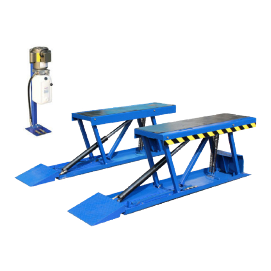
- Page 1 PL6K 6600 POUND CAPACITY LOW RISE PIT Installation and Operation Manual REV A-062813...
- Page 4 6,000 POUND CAPACITY LOW RISE PIT LIFT This instruction manual has been prepared especially for you. Your new lift is the product of over 20 years of continuous research, testing and development; it is one of the most technically advanced lifts on the market today. READ THIS ENTIRE MANUAL BEFORE INSTALLATION &...
- Page 5 There is no other express warranty on the Tuxedo lifts and this warranty is exclusive of and in lieu of all other warranties, expressed or implied, including all warranties of merchantability and fitness for a particular purpose.
-
Page 6: Definitions Of Hazard Levels
IMPORTANT NOTICE OWNER’S RESPONSIBILITY Do not attempt to install this lift if you have never been To maintain the lift and user safety, the responsibility of the owner is to read and follow these instructions trained on basic automotive lift installation procedures. Never attempt to lift components without proper lifting ... -
Page 7: Table Of Contents
TABLE OF CONTENTS Contents Page No. Serial Number ................2 Warranty . -
Page 8: Installer / Operator Agreement/ Protective Equipment
INSTALLER OPERATOR PLEASE READ AND FULLY UNDERSTAND. BY PROCEEDING YOU AGREE TO THE Failure to follow danger, warning, and caution instructions FOLLOWING. may lead to serious personal injury or death to operator or bystander or damage to property. I have visually inspected the site where the lift is to be installed and verified the concrete to be in good condition and free of cracks or other defects. -
Page 9: Introduction
INTRODUCTION 1. Carefully remove the crating and packing materials. 2. Check the voltage, phase and proper amperage CAUTION! Be careful when cutting steel banding requirements for the motor shown on the motor plate. material as items may become loose and fall causing Wiring should be performed by a certified electrician personal harm or injury. -
Page 10: Tools Required
TOOLS REQUIRED Rotary Hammer Drill Or Similar Medium Crescent Wrench 3/4” ; 1 1/4” Masonry Bits Crow Bar Chalk Line Hammer 4 Foot Level Medium Flat Screwdriver Open-End Wrench Set: 1/2””,15/16” - 1-1/8” Tape Measure: 25 Foot Suggested Socket And Ratchet Set: 1-1/8” NOTE: An air supply (30 PSI Min / 3 CFM Min.) will be required for the safety-lock mechanisms. -
Page 11: Packing List
CAUTION! This lift should be installed by qualified lift installers only who are familiar with this particular lift model and the requirements thereof. The frame on this lift MUST NOT be twisted, bent or misaligned by un-level floors or improper anchoring. Misalignment may cause damage to the lift. -
Page 12: Main Assembly View / Description Of Parts
Main Assembly View Floor plan NOTE: The maximum recommended width between pads is 38”. Consult the factory for applications that require installations wider than 38”. - Page 13 Lift size Basic Specification Description Capacity Lifting Time Overall Height Platform Width Overall Length Low Rise Pit Lift 3.0 ton ( about ) 4 3/16” -- 26 3/16” 18” 83 1/4” 6000lbs 35 Sec 107-- 665mm 457 mm 2114mm...
-
Page 14: Step 3 / Locating Lift
Fig. 3.1 STEP 3 (Locating Unit) NOTE: The maximum recommended width between pads is 38”. Consult the factory for applications that require installations wider than 38”. 4. After selecting a site, place each unit in position. The Cylinders MUST be placed towards the inside. 1. -
Page 15: Step 4 / Power Unit Location
STEP 4 (Locating Power Unit) 1. Select a site for the Power Unit so that operators have a full unobstructed view of the lift. 2. It is recommended that the Hydraulic Hose and Air Safety Line for the lift be routed through the floor at the base of the Power Unit, so check for routing clearances. -
Page 16: Step 6 / Power Unit Installation
STEP 6 2. Install the 90 Degree Hydraulic Fitting in the pressure (Power Unit Installation) port of the Power Unit. The pressure port is covered with a plastic plug. Use teflon tape on pipe fittings ONLY. 3. After the fitting is installed correctly, connect the 140” Hydraulic Hose making sure to not over-tighten. - Page 17 2. Fill the reservoir with 10 WT. HYDRAULIC OIL OR DEXRON TYPE III ATF, approximately 6.5 quarts. Make sure the funnel used to fill the power unit is clean. 3. The standard power unit for your lift is 110 volt, 60HZ, single phase.
-
Page 18: Step 7 / Routing Air Lines
STEP 7 (Routing Air Lines) Connect the Air Safety Cylinders to the Air Safety Valve using the Tee Fitting and the Airline. Route the air line as shown below making sure to position the push button air valve with the INLET facing towards the AIR SOURCE and the OUTLET facing towards the lift. -
Page 19: Step 8 / Anchoring Lift Assemblies
STEP 8 4. Using Compressed air or vacuum, remove all excess dust from holes, then install the anchor bolts. (See (Anchoring the Lift Assemblies) Fig 8.3) IMPORTANT NOTE: This lift is supplied with installation instructions and concrete fasteners meeting criteria prescribed by the American National Standard "Automotive Lifts... -
Page 20: Step 10 / Lift Start Up / Final Adjustments
STEP 10 KEEP HANDS AND FEET CLEAR. Remove hands (Lift Start Up / Final Adjustments) Make sure the Power Unit Reservoir is full with 6.5 and feet from any moving parts. Keep feet clear of lift quarts of 10-WT hydraulic oil or Dexron-III automatic when lowering. -
Page 21: Step 11 / Operation/ Maintenance
STEP 11 Make sure lift is in fully lowered position. (Operating Instructions) Drive vehicle over the lift making sure that the center-line of the vehicle is positioned properly over the lift pads. Set parking brake or use wheel chock to hold vehicle in position. - Page 22 Lower the lift onto the nearest safety lock. ALWAYS INSURE SAFETY LOCKS ARE ENGAGED before entering work area. WARNING! Check to make sure safeties are engaged on the SAME safety lock position BEFORE ENTERING YOU MUST RELEASE THE AIR SAFETY BUTTON work area.
- Page 23 Safe Lift Operation Automotive and truck lifts are critical to the operation and profitability of your business. The safe use of this and other lifts in your shop is critical in preventing employee injuries and damage to customer’s vehicles. By operating lifts safely you can insure that your shop is profitable, productive and safe.
- Page 24 DO NOT Leave the controls while the lift is still in motion. DO NOT stand directly in front of the vehicle or in the bay when vehicle is being loaded or driven into position. DO NOT Go near vehicle or attempt to work on the vehicle when being raised or lowered. REMAIN CLEAR of lift when raising or lowering vehicle.
- Page 25 6600Lbs. / 3000Kg 3300Lbs. / 1500Kg 3300Lbs. / 1500Kg...
-
Page 27: Troubleshooting Guide
LIFT WILL NOT RAISE POSSIBLE CAUSE 1 Air in oil, (1,2,8,13) 2 Cylinder binding, (9) 3 Cylinder leaks internally, (9) 4 Motor runs backward under pressure, (11) 5 Lowering valve leaks, (3,4,6,10,11) 6 Motor runs backwards, (7,14,11) 7 Pump damaged, (10,11) 8 Pump won’t prime, (1,8,13,14,3,12,10,11) 9 Relief valve leaks, (10,11) 10 Voltage to motor incorrect, (7,14,11) - Page 28 MOTOR WILL NOT RUN POSSIBLE CAUSE Fuse blown, (5,2,1,3,4) Limit switch burned out, (1,2,3,4) Microswitch burned out, (1,2,3,4) Motor burned out, (1,2,3,4,6) Voltage to motor incorrect, (2,1,8) REMEDY INSTRUCTION 1. Check for correct voltage......Compare supply voltage with voltage on motor name tag.
- Page 29 WILL NOT RAISE LOADED LIFT POSSIBLE CAUSE 1. Air in oil, (1,2,3,4) 2. Cylinder binding, (5) 3. Cylinder leaks internally, (5) 4. Lift overloaded, (6,5) 5. Lowering valve leaks, (7,8,1,5,9) 6. Motor runs backwards, (10,12,9) 7. Pump damaged, (5,9) 8. Pump won’t prime, (1,2,3,4,5,11,9) 9.
- Page 30 LIFT WILL NOT STAY UP POSSIBLE CAUSE 1. Air in oil, (1,2,3) 2. Check valve leaks, (6) 3. Cylinders leak internally, (7) 4. Lowering valve leaks, (4,5,1,7,6) 5. Leaking fittings, (8) REMEDY INSTRUCTION 1. Check oil level....... The oil level should be up to the bleed screw in the reservoir [with the lift all the way down.] 2.
-
Page 31: Main Parts Listing
PARTS DRAWING 60-1 32-1 58-1 39 38 Option parts... - Page 32 PARTS LIST CODE DESCRIPTION NOTE 161109E*01-001 left base 161109E*01-001-1 right base 161109E*01-002 long shaft 161109E*01-003 self-lock nut 161109E*01-004 sleeve 161109E*01-005 bolt M10*90 161109E*01-006 spring 161109E*01-007 long threaded rod 161109E*01-008 self-lock nut 161109E*01-009 bolt M6*25 161109E*01-010 air fitting 1/8 φ6 161109E*01-011 air pipe φ6 L=4 meter 161109E*01-012...
- Page 33 CODE DESCRIPTION NOTE 161109E*01-040 short oil hose 161109E*01-041 bolt M10*80 161109E*01-042 anchor M8*80 161109E*01-043 pump stand 161109E*01-044 blocked nut 161109E*01-045 T-fitting 161109E*01-046 O-ring φ10*2.4 161109E*01-047 self-lock nut 161109E*01-048 air valve 161109E*01-049 short air pipe φ6 L=1.5 meter 161109E*01-050 Y-fitting 1/8 φ6 161109E*01-051 motor pump 220V 60HZ...
-
Page 34: Maintenance Records
MAINTENANCE RECORDS... - Page 36 IMPORTANT POWER UNIT PRIMING PROCEDURE THE PROBLEM: Power unit runs fine but will not pump any fluid. Step 1 – Locate the check valve, the flush plug to the left of the lowering valve. (See drawing below.) Step 2 – Using an Allen wrench and shop towel – with shop towel in place to catch fluid –...
Need help?
Do you have a question about the PL6K and is the answer not in the manual?
Questions and answers