Table of Contents
Advertisement
Quick Links
.
9,000
LB
T
P
L
WO
OST
IFTS
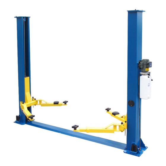
9,000 lb. capacity lifts. These lifts have the heavy-duty leaf chain,
the steel pulleys, the high-strength cable equalization system
and everything you'd expect from a quality lift.
TP
9 KAC
Asymmetric
Clear floor
model
Features:
9,000 lb. lifting
capacity
Dual cylinders with
low friction chain rollers
Low profile automatic
arm restraints
1
⁄
" and 5"
1
2
stackable drop-in
height adapters
Electric override
automatic safety shut-off
(Clear floor model)
Powder-coated
paint finish
FREE mounting
hardware
S
:
PECIFICATIONS
Capacity
Lifting speed
Power pack
Amperage
Low pad height
Lifting height with adapters
Width overall
Height overall
Shipping weight
TP
9 KF
Floor plate
model
TP 9 KAC
TP 9 KF
9,000 lbs.
9,000 lbs.
50 sec.
50 sec.
2hp 220 vac
2hp 220 vac
20 amps
20 amps
4
1
⁄
"
4
1
⁄
"
2
2
75
⁄
"
75
⁄
"
1
1
2
2
134"
134"
142"
111
1
⁄
"
2
13 ,
90 lbs.
12 5 9
,
lbs.
Advertisement
Table of Contents


Need help?
Do you have a question about the TP9KF and is the answer not in the manual?
Questions and answers