
Related Manuals for Tuxedo FP8K-DS


Summary of Contents for Tuxedo FP8K-DS
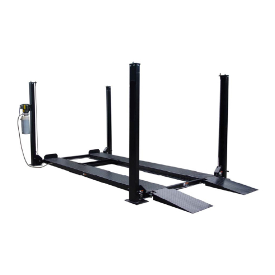
- Page 1 FP8K-DS & FP8K-DS-XLT Four Post Parking Lifts 8,000 lbs. Capacity (4,000 lbs. per axle) INSTALLATION / OWNERS MANUAL July 2015-B...
-
Page 2: Table Of Contents
Any other proposed application of this equipment should be documented and submitted in writing to the factory for examination. The user assumes full responsibility for any equipment damage, personal injury, or alteration of the equipment described in this manual or any subsequent damages. FP8K-DS / FP8K-DS-XLT July 2015-B... - Page 3 94-1/2” 100-5/16” Length between Post 157-1/2” 172-1/2” Max Clearance / Under Track 70” 78” Locking Positions Lifting Speed 100S Power 110V-15 Amp / 1PH 110V-15 Amp / 1PH Ship Weight 1,690 lbs. 1,785 lbs. LAYOUT FP8K-DS / FP8K-DS-XLT July 2015-B...
- Page 4 FP8K-DS / FP8K-DS-XLT July 2015-B...
-
Page 5: Tools Required
The Power unit is not water proof!!! DO NOT install lift close to wall. It is necessary to leave adequate clearance for safely walking. Suggest clearance be 1 meter (3 feet) at min. FP8K-DS / FP8K-DS-XLT July 2015-B... -
Page 6: Main Components & Accessory Identification
Power Unit Mainside Runway Drive-On Ramps Steel Caster Kit OPTIONAL ACCESSORIES NOT SHOWN: • FP8K-DS Drip Trays & FP8K-DS-XLT Drip Trays • SJ-35 Sliding Scissor Jack – 3,500 lbs. capacity • Poly Casters • Aluminum Drive-On Ramps FP8K-DS / FP8K-DS-XLT... -
Page 7: Installation Instructions
Refer to Figure 4 for Cable routing detail. Also, ensure Cable Guide Bolts are installed, as shown below. These assist in keeping the Cables properly engaged to the pulleys. Cable Guide Bolts (Install Cable Guide Bolts, after routing Cables around Pulleys. This maintains the Cables stay on Pulleys) FP8K-DS / FP8K-DS-XLT July 2015-B... - Page 8 Figure # 1. 13. Secure Top Cap and Lock Ladder assemblies together with Washer and Nut (Items # 7 & 8). Position the Crossbeams at the second lowest locking position on all columns. Top Cap FP8K-DS / FP8K-DS-XLT July 2015-B...
- Page 9 Install the Offside Runway (Item # 52) opposite from the Mainside Runway (Item # 51) and Power Unit Column as shown in Figure # 1. Note: The Mainside Runway must be installed on the same side as the Power Unit Column. Mounting Plate FP8K-DS / FP8K-DS-XLT July 2015-B...
- Page 10 Adjust to level the lift. Note: You may have to loosen the Nut under the Top Plate to make leveling adjustments. 22. After leveling is complete, tighten the Nut on the Lock Rod, located underneath the Top Cap on each post. This will lock the Lock Ladder in position. FP8K-DS / FP8K-DS-XLT July 2015-B...
- Page 11 NOTE: Lubricate ALL Cable Sheaves, Bearings and Shafts with grease prior to operating Lift. The Lift Installation is now complete. (See following pages for Caster Kit & Anchoring Instructions, if required) CAUTION: Read Safety & Operation Instructions before operating lift. FP8K-DS / FP8K-DS-XLT July 2015-B...
-
Page 12: Caster Kit Assembly / Installation
4. Lower lift and the columns will automatically raise off the floor. NOTE: This Lift does not require bolting to the floor (BUT) If you choose the option to anchor the Lift to the floor, please follow the criteria & detailed instructions on next page. FP8K-DS / FP8K-DS-XLT July 2015-B... -
Page 13: Foundation & Anchoring Requirements
Run nut down just Tighten nut with carbide tipped below impact section Torque wrench to masonry drill bit per of bolt. Drive anchor 130 ft.-lbs. ANSI standard into hole until nut and B94.12.1977 washer contact base. FP8K-DS / FP8K-DS-XLT July 2015-B... -
Page 14: Safety Instructions & Procedures
Motors and all electrical components are not sealed against the weather and moisture. Install this lift in a protected indoor location. Failure by the owner to provide the recommended shelter could result in unsatisfactory lift performance, property damage, or personal injury. FP8K-DS / FP8K-DS-XLT July 2015-B... -
Page 15: Operation Instructions
UNDER THE VEHICLE. NEVER ALLOW ANYONE TO GO UNDER THE LIFT WHEN RAISING OR LOWERING. NOTE: It is normal for an empty lift to lower slowly - it may be necessary to add weight. Read and adhere to all WARNING, CAUTION and SAFETY INSTRUCTIONS labels on lift. FP8K-DS / FP8K-DS-XLT July 2015-B... -
Page 16: Preventive Maintenance Schedule
Check for excessive wear of cable. Replace them if necessary. Change the hydraulic fluid - operating temperature, type of service, contamination levels, filtration, and chemical composition of fluid should be considered. If operating in dusty environment shorter interval may be required. FP8K-DS / FP8K-DS-XLT July 2015-B... -
Page 17: Troubleshooting
1. Cross beam ends are rubbing the columns. Readjustment needed. 2. Cylinder too tight, load lift half capacity and cycle up and down a few times to break in. 3. May have excessive wear on cable sheaves or shafts. Replace them. FP8K-DS / FP8K-DS-XLT July 2015-B... -
Page 18: Power Unit Priming Procedure
Step 3 – Push the START button for one second, then release for three seconds. Repeat these steps until unit starts pumping fluid. Step 4 – Tighten the check valve plug. YOUR POWER UNIT SHOULD BE PRIMED FP8K-DS / FP8K-DS-XLT July 2015-B... -
Page 19: Latch & Cable Inspection / Adjustments
Latches may not click in at the same time when vehicle is being raised but should be close. Be sure all four corners have passed the locking latch bar slot before lowering lift on locking latches. FP8K-DS / FP8K-DS-XLT July 2015-B... -
Page 20: Exploded Views
EXPLODED VIEW Figure 1 FP8K-DS / FP8K-DS-XLT July 2015-B... - Page 21 EXPLODED VIEW Figure 2 FP8K-DS / FP8K-DS-XLT July 2015-B...
- Page 22 EXPLODED VIEW Figure 3 FP8K-DS / FP8K-DS-XLT July 2015-B...
- Page 23 EXPLODED VIEW Figure 4 FP8K-DS / FP8K-DS-XLT July 2015-B...
- Page 24 EXPLODED VIEW Figure 5 FP8K-DS / FP8K-DS-XLT July 2015-B...
-
Page 25: Parts List
M8X35 GB95 Flat Washer TT7B-200-14 Nylon Block GB95 Flat Washer TT7B-200-06 Spindle TT7B-200-05 TT7B-200-04 Safety Block TT7B-200-07A/B Torque Spring GB6170 Hex Nut TT7B-200-02 Bushing TT7B-200-03-00A/B Locking Block GB93 Spring Washer GB6170 Hex Nut TT7B-200-15 Spring FP8K-DS / FP8K-DS-XLT July 2015-B... - Page 26 GB6170 Hex Nut TT7B-200-01-00 Crossbeam TT7B-500-02 Connecting Rod L=2080 TT7B-500-03 Anchoring Bolt TT7B-500-01 Connecting Rod L=215 Knob DPF4-3.2-400-01-00 Handle DPF4-3.2-400-04 Bushing DPF4-3.2-400-03 Connection Coupler DPF4-3.2-400-11 Connecting Rod DPF4-400-02-00 Connecting Rod GB889 SI6TK Bearing DPF4-3.2-400-09 Spacer FP8K-DS / FP8K-DS-XLT July 2015-B...
- Page 27 DPF4-3.2-500-11 Hydraulic Hose TPF4-500-05 Tee Fitting TPF4-500-09 TPF4-500-08 Washer TPF4-500-07 Fitting Steel Cable A – FP8K-DS 26’ 9-7/8” TT7B-500-03A Steel Cable B – FP8K-DS 22’ 1-3/4” TT7B-500-03B Steel Cable D – FP8K-DS 8’ 10-5/8” TT7B-500-03D Steel Cable C – FP8K-DS 13’...
- Page 28 There is no other express warranty on the Tuxedo lifts and this warranty is exclusive of and in lieu of all other warranties, expressed or implied, including all warranties of merchantability and fitness for a particular purpose.
Need help?
Do you have a question about the FP8K-DS and is the answer not in the manual?
Questions and answers