Table of Contents
Advertisement
Quick Links
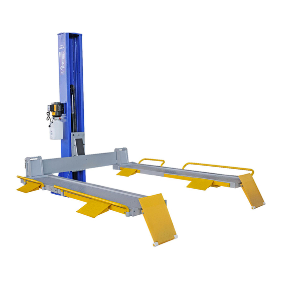
SC-2K-UTV-X
SINGLE COLUMN UTV & MOWER
STORAGE / SERVICE LIFT
2,000 lbs. Capacity (908 Kg)
INSTALLATION & OPERATION MANUAL
IMPORTANT!!
READ MANUAL THOROUGHLY BEFORE ASSEMBLING, OPERATING, OR MAINTAINING LIFT
TABLE. WHEN COMPLETED WITH ASSEMBLY, ENSURE TO RETURN MANUAL & RELATED
DOCUMENTS IN PROTECTIVE SLEEVE AND GIVE TO THE OWNER / OPERATOR.
SC-2K-UTV-X
APR 2024
Advertisement
Table of Contents

Related Manuals for Tuxedo IDEAL SC-2K-UTV-X


Summary of Contents for Tuxedo IDEAL SC-2K-UTV-X
- Page 1 SC-2K-UTV-X SINGLE COLUMN UTV & MOWER STORAGE / SERVICE LIFT 2,000 lbs. Capacity (908 Kg) INSTALLATION & OPERATION MANUAL IMPORTANT!! READ MANUAL THOROUGHLY BEFORE ASSEMBLING, OPERATING, OR MAINTAINING LIFT TABLE. WHEN COMPLETED WITH ASSEMBLY, ENSURE TO RETURN MANUAL & RELATED DOCUMENTS IN PROTECTIVE SLEEVE AND GIVE TO THE OWNER / OPERATOR.
-
Page 2: Table Of Contents
Table of Contents Safety & Cautions…………………………………………………………………… Pages 3 - 4 · Important Statements · Qualification of Operators and Users · Cautions · Training · Owners / Employer Responsibilities Product Information………………………………………..………………………. Pages 4 - 7 · Description · Specifications · Dimensions ·... -
Page 3: Safety & Cautions
1. Safety & Cautions Important Statements: Please note the max weight capacity noted on the silver ID tag attached to the main post. Do not try to lift any load that exceeds the rated lifting capacity. Please read this manual carefully before installation and use of the lift, to avoid any property loss or personal injury caused by faulty operation. -
Page 4: Owners / Employer Responsibilities
In addition, iDEAL SC-2K-UTV-X 2,000 lb. Lift comes standard with durable powder-coat finish, 8ea multi-position side ramps, wheel stop ‘pivot’ ramps with protective nylon rollers, quick removal tubular wheel stop bars for platform sides. -
Page 5: Dimensions
Dimensions: SC-2K-UTV-X APR 2024... -
Page 6: Receiving & Handling
Receiving & Handling: Unloading the Lift: You will need a forklift that can handle a minimum of 2,500 pounds and operates on a smooth surface to unload from freight carrier trailer. The lift packaging weighs close to 1,700 pounds, not including any optional accessories that may be included. Un-banding the Lift: The steel bands which secure the lift packaging are heavy duty. -
Page 7: Foundation & Anchoring Requirements
Operating Conditions: The Lift is not intended for outdoor use and has an operating ambient temperature range of 41º - 104ºF (5º - 40ºC). DO NOT install this lift outdoors unless special consideration has been made to protect the power unit from weather conditions. -
Page 8: Installation Instructions
3. Installation Instructions WARNING!! Improper installation can cause accelerated wear, resulting in catastrophic failure which may cause property damage and / or bodily injury. Manufacturer will assume no liability for loss or damage of any kind, expressed or implied, resulting from improper installation or use of this product. -
Page 9: Bolster Beam Mounting To Column
2) With column still in the horizontal position, ensure the lift carriage positioned to base of column. If not, slide carriage to base, while pulling the latch release cable at the same time. This will assist when standing column into position, by lowering the column’s center-of-gravity. Fig. 3. Lift Carriage Latch Release... - Page 10 2) For the remaining 6ea mount holes, use the ‘longer’ M16 x 40mm socket head bolts, lock washers & flat washers to finish connecting the bolster beam & carriage together. Ensure all bolts are securely tightened. Fig. 5. NOTE: apply ‘short’...
- Page 11 Step 6: Power Unit Electrical Connection (Standard 115V) WARNING: Electrical Wiring must comply with local code. Use separate circuit for each power unit and protect each circuit with time delay fuse. For 110V-115V single phase, use 20 amp fuse. Connect 115VAC electrical power to the Power Unit’s three prong electrical plug. Ensure to use proper size extension cord &...
- Page 12 Step 7-A: Platform ‘Angle’ Adjustment Tips: The SC-2K-UTV-X Lift come with the ability to adjust the platform ‘deflection’ angle, based on the type & weight of vehicle(s) being lifted for storage and/or service, along with the position of the vehicle on the platforms. To adjust the platforms deflection angle, use one or a combination of the 3ea different thickness of platform shim plates, included with Lift.
-
Page 13: Mounting Ramps, Wheel Stop Bars & Latch Cable Bracket
Step 8: Mounting Ramps, Wheel Stop Bars & Latch Cable Bracket 1) Mount the ‘pivoting’ platform wheel stop ramps to each end of platforms. Connect to platforms using the pivot pin, apply snap rings at each end of pivot pin to secure to platforms. Fig. 19. 2) Insert side ramps into brackets on each side of platforms, as required. -
Page 14: Starting Up / Testing
4. Starting Up / Testing NOTE: Do not place any vehicle on the lift platforms at this time. To Raise, push the power switch button on the power unit and hold while the electric motor turns on. The motor operates an internal pump that forces hydraulic oil into the lift cylinder, which extends the piston rod &... -
Page 15: Operation Instructions
5. Operation Instructions Vehicle Positioning, Raising & Lowering VEHICLE POSITIONING: v Determine which loading direction the vehicle will be for Front or Side loading. v For Front Loading, adjust the Platform’s width to match the center of vehicle’s wheels to the center of each platform. v For Side Loading, determine the approach side and adjust the Platform’s width to match the center of vehicle’s wheels. -
Page 16: Troubleshooting
6. Troubleshooting Common lift issues may be encountered over time. Please see probable causes & possible solutions covered in the paragraphs below. If the troubleshooting guide does not provide assistance to resolve the lift issue(s), please contact the distributor / manufacturer for help. We will help you solve the problem as soon as possible. Ø... -
Page 17: Power Unit Priming Procedure
Power Unit Priming Procedure THE PROBLEM: Power unit runs fine but will not pump any fluid. WARNING!! Failure to properly relieve hydraulic pressure in the following steps can cause injury to personnel. Step 1 – Locate the check valve, the flush plug to the left of the lowering valve. Step 2 –... -
Page 18: Preventive Maintenance
7. Preventive Maintenance The periodic Preventive Maintenance Schedule provided is the suggested minimum requirements at minimum intervals for Daily, Weekly & Yearly periods or accumulated hours, whichever comes sooner. Periodic maintenance is to be performed on a Daily, Weekly, and Yearly basis as given in the following paragraphs. -
Page 19: Exploded Views
Exploded Views SC-2K-UTV-X APR 2024... - Page 20 (Hydraulic Schematic) 1. Reservoir Tank 7. Release Valve (Manual) 2. Steel Mesh Filter 8. Overload Relief Valve 3. Gear Pump 9. Restrictor Valve 4. Motor 10. Hydraulic Cylinder 5. Check Valve 11. Oil Suction Tube 6. Screen Mesh (Release Valve) SC-2K-UTV-X APR 2024...
-
Page 21: Parts List
Parts List ITEM TUX P/N M-REF P/N DESCRIPTION QTY. SC-2K-UTVX-001 DJ05-10000-000 Anchor Bolt, 3/4” x 5.5” SC-2K-UTVX-002 TC02-01000-000 Column PU-110V-S-K MBZ07 110-115V DURO Power Unit, Short Tank SC-2K-UTVX-004 5105-06020-001 Screw, M6 x 20mm SC-2K-UTVX-004 DJ01-00005-M00 Top Cap SC-2K-UTVX-006 5104-08030-001 Bolt, M8 x 30mm SC-2K-UTVX-011 Latch Bracket Screw SC-2K-UTVX-012... - Page 22 SC-2K-UTVX-037 DJ01-13002-M00 Latch Cam SC-2K-UTVX-038 5206-00010-000 Thin Lock Nut, M10 SC-2K-UTVX-039 DJ01-13003-M00 Latch Release Cable SC-2K-UTVX-040 TC02-02100-000 Carriage SC-2K-UTVX-041 DJ01-00029-M00 Upper, Nylon Block SC-2K-UTVX-042 DJ01-00028-M00 Side, Nylon Block SC-2K-UTVX-043 DJ01-00027-M00 Nylon Block Frame SC-2K-UTVX-044 5110-04010-000 Screw, M4 x 10mm SC-2K-UTVX-045 5104-08025-001 Hex Bolt, M8 x 25mm SC-2K-UTVX-046...
- Page 23 SC-2K-UTVX-087 TC02-00013-000 Short, Safety Wheel Stop Bar SC-2K-UTVX-088 5301-00008-000 Large Flat Washer, M8 SC-2K-UTVX-089 DJ05-00020-000 Power Unit Mount Bracket SC-2K-UTVX-090 5301-00008-000 Lock Washer, M8 SC-2K-UTVX-091 DJ01-00008-000 Latch Release Cable Bracket SC-2K-UTVX-092 TC02-00011-000 Hyd. Fitting Connector - 1 SC-2K-UTVX-093 TC02-00000-000 Hyd. Flow Restrictor Valve SC-2K-UTVX-094 TC02-00020-000 Hyd.
-
Page 24: Limited Warranty Policy
There is no other express warranty on the Tuxedo lifts and this warranty is exclusive of and in lieu of all other warranties, expressed or implied, including all warranties of merchantability and fitness for a particular purpose.
Need help?
Do you have a question about the IDEAL SC-2K-UTV-X and is the answer not in the manual?
Questions and answers